Longboy's "WEBSTER" I/C engine.

Home Model Engine Machinist Forum

Help Support Home Model Engine Machinist Forum:

This site may earn a commission from merchant affiliate links, including eBay, Amazon, and others.
Longboy said:
.......There's about 5 other Webster engines on "You Tube"! If my experiance gets others in gear I'm happy to tell the story.

Well, you got me in gear. I finished my Webster several years ago and never could get it running. Tonight I tried again and guess what...it started and ran.

IMG_0320.jpg
 
.....Well Charlie, Looking good. I didn't know I had such influence on your closeted Webster........at least to the point it would just decide to start up!
 
I find the part about the "radiator" being "epoxied " into place very interesting. A few years ago I was involved in a research project in which we were trying to draw heat away from specific areas on a die casting mold to make the molten aluminum in the mold harden in a pattern. We found that even with a hard press fit and no epoxy, that heat transfer across two different pieces of metal was very poor, as compared to heat transfer though a contiguous piece of metal.---And when we tried it using any kind of epoxy, it was even worse. We ended up getting our best thermal transfer properties when we used a special "heat transfer paste" which has a very high percentage of finely ground copper in its make up.---Brian
 
Charlie, did you change something to get it running? Or did it just need to age for a while? :big:

Chuck
 
That's a real nice runner, Longboy. The OS carb really lets it idle down to a nice slow speed. Sounds just like a small Briggs!

Chuck
 
Thanks Brian. The epoxy is applied with a Q-tip just beyond the flange and counterbore and just enough to hold the two parts together. Necessary to align the cyl. port with the radiator bolt pattern when installed to the head. Epoxy as a fluid into the mold an easy experiment but unlikely its polymers would act as a "chill bar" as the copper metal compound would offer.
 
Thanks Chuck, Theres a young man on "You Tube" with a Webster and he must have a 2-3 lbs. 5 inch flywheel on it..........he must have his idle down to 700!
 
Excellent build Longboy! :bow: :bow: :bow:

Congratulations on your runner as well Charlie.

Rick
 
cfellows said:
Charlie, did you change something to get it running? Or did it just need to age for a while? :big:

Chuck

It felt like the O-ring was dragging too much. I cut the ring groove a few thousandths deeper and it felt much better. After that it was just a matter of getting the carb adjusted.

Charlie
 
Refer back to the last photo of post#19....."Why the offset on the cylinder Longboy"? On Joe's web page describing his engine, He mentioned its needs for more cooling area, an easy solution.
IM001269-1.jpg
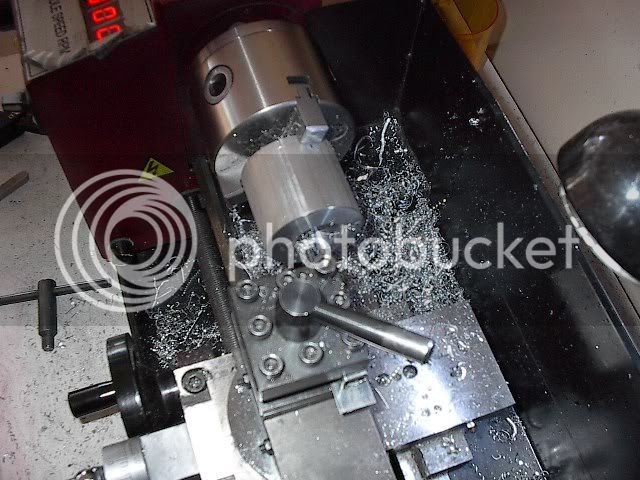
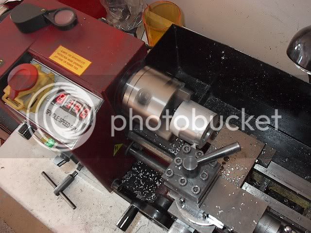
.......Two ways to achieve this would be 1) cut down the Websters dog leg frame adjacent to the cylinder another 1/4 inch to clear a 2 inch dia radiator. 2) offset away from the frame . With one of the outside jaws providing the offset to the material, I "almost" got enough clearance.
IM001270.jpg
........after the boring with the same offset another intermediate cut of .020 had to come from the outer diameter. A notch also had to be cut into the radiators face to clear the valve block.
 
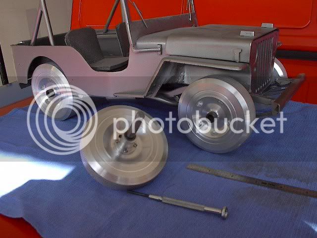
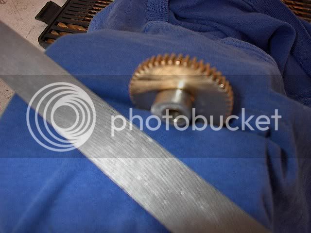
.........It was mentioned the flywheel has been knurled. This was totally accidental and not my planning as it already existed. Here is the source!
IM001287.jpg
A "spare" that was never used on a 1/8 scale model of my Willys CJ-3A done in class when I learned machine tools and welding. Already drilled 5/16, a hub had to be made for it. Drilled and not reamed 5/16th. the hub was aligned with the flywheel with a transfer punch and four #2-56 screws hold them together. There is no discernible runout.
 
Making a tire tread with a knurling tool is a good idea!

Chuck
 
.........In troubleshooting my engines start-up problems, I found that after TDC on the intake stroke that the rocker arm was lifting the exhaust valve a hair. I couldn't clear it with the rocker adjustment screw to my satisfaction. Filed the cam ramp at the appropriate point and then the engine responded!
IM001292-1.jpg
Engine valves..........stainless?.......drillrod?........how 'bout a hardware grade 5 bolt!
IM001295.jpg
Starting with a 3 1/2 inch long 5/16th....."Isn't that like taking a railroad spike to make a toothpike Longboy"? Well you have 2 1/2 inches of unthreaded shank to chuck up on and to cut your stem dia. to finished length. A center in the tail stock supported the soon to be valve head. The #60 hole for the spring retainer pin was drilled before the shank turn down and the valve head wasn't faced to remove the grade marking.
 
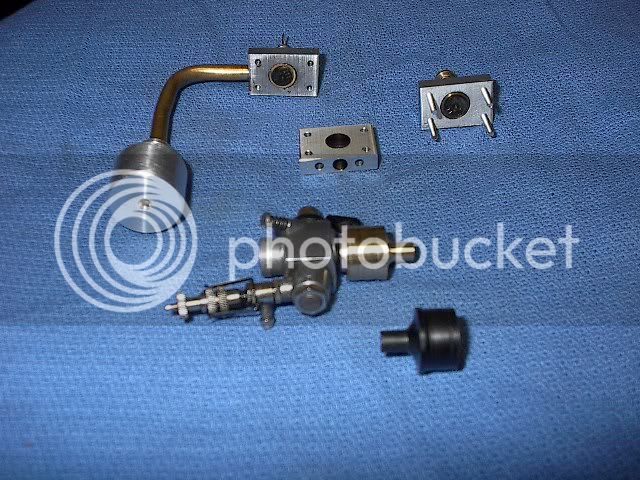
..........I was getting some fuel puddling hanging from the exhaust valve block segment in initial run in. Joe's notes say if the 3 blocks are square enough no gasket needed then. Ordinary Scotch tape between the segments is now the invisible seal. The black object is the original Delrin carb to valve block manifold. I had concerns that it would get too hot and changed to brass which with a brass air horn intake is more show worthy.
IM001294.jpg
 
Longboy said:
The black object is the original Delrin carb to valve block manifold. I had concerns that it would get too hot and changed to brass

Good thinking. My engine uses a Perry carb that has a molded plastic body. After a few minutes of running the plastic was starting to melt.

Charlie
 

Latest posts

Back
Top