Forgive me for the lull in my sequence of construction, as well as the rather poor picture quality; these were from back when only 35mm action was in my repertoire.
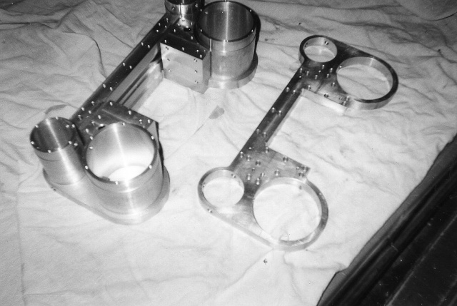
First, the cylinder block parts, partially assembled. This consists of 9 parts in total, excluding the valve and cylinder liners. These 9 are of 6061-T651 aluminum, The plate on the right, with 2 big and 2 smaller holes, there are 2 of these, pressed onto the ends of the cylinder and valve sleeves, seen to the left, with the other plate already in place, at the bottom of the stack. In addition to the press fit, the plates are securely screwed to a wide block, about 1" thick by 3" wide. This block contains the passage which carries the exhaust steam to the center, between the cylinders, and exits upward through the exhaust nozzle stand, which screws down to the top of the block from within the smokebox. 2 smaller blocks may be seen which are screwed to the inside vertical edge of the plates, and the cross-block at top. These smaller blocks straddle the engine frames, being screwed to them from the the inside by 1/4-20 socket head capscrews.
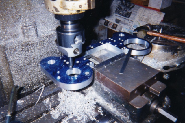
The next view shows one of the plates being made up in the Bridgeport mill. Wherever possible, I try to design parts in such a way, given their size allows, that they may be held in the machine's vise, rather than clamped down as a workpiece often must be.
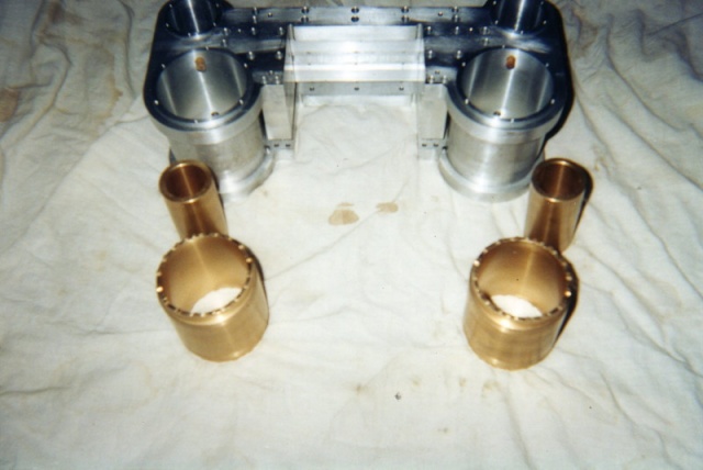
The valve and cylinder liners, of bronze, are seen in the last pic. They were at that point incomplete, as the steam ports and passages still had to be made. Again, my apologies, at the time of this work, I was still very "green", and had no idea what a forum was, or much less, it's need for good, descriptive illustrations. Thank you for your interest! In the event I missed some pertinent point, or any other questions should arise, I am always happy to answer! jack





![MeshMagic 3D Free 3D Modeling Software [Download]](https://m.media-amazon.com/images/I/B1U+p8ewjGS._SL500_.png)


![DreamPlan Home Design and Landscaping Software Free for Windows [PC Download]](https://m.media-amazon.com/images/I/51kvZH2dVLL._SL500_.jpg)


