Lady Stephanie

Home Model Engine Machinist Forum

Help Support Home Model Engine Machinist Forum:

This site may earn a commission from merchant affiliate links, including eBay, Amazon, and others.

methuselah1

Well-Known Member
Joined
Jan 28, 2020
Messages
185
Reaction score
51
Hello Chaps! I'm building one of these engines, and I wonder if anyone has any advice regarding the lower covers? I have cut the steel, I've purchased the half-round brass beading, but I haven't worked out how to actually DO it! Of course, if anyone can let me have a copy of the EIM article(s) that would be extra cool!

-Andrew UK
 
Thanks for that^^ I have terrible trouble uploading pictures here for some reason!
 
But I notice that fella has chosen to side step the half round beading approach.... If the photo works, this is what a side cover should look like...
phpThumb_generated_thumbnail.jpg
 
For the book, the design is essentially modelled on half of the pumping engine installed at the Dancer's End water pumping station, near Tring. The original engine house is still there.

Here's the prototype...

Dancer's End.jpg


I think it now resides at the Kew Bridge Steam Museum, around the corner from the botanical gardens.

-Andrew UK
 
Not seen the articles but if faced with having to do it these are my thoughts

For the curved corners turn up some stock into a suitable size tube and form a half round on the end with a form tool, part off and then repeat the half round and parting until you have a series of rings with a half round section.

Cut these with suitable mitered ends to mate with cut lengths of your beading again with suitably mitred ends.

Fix to the plates either by soft solder or a modern adhesive such as JBWeld

Not heard the one about it being based on half that engine before, more likely based on one of the coffer based engines that went out to the west indies to work on the sugar estates as it's quite small if scaled up and not of the size usually seen in pumping stations, possibly pumping to a large private estate at most
 
Last edited:
hello
My next project is a lady stephanie beam pump. They look fantastic. I haven't made many models but was a machinist most of my working life, (77 yrs old now). I'm going to get the casting kit but am strangely nervous as to if I'm still up to fine machining. Too ambitious you think? Any advice especially on how/where to start gratefully received. Any things to look out for? I've got an old myford 7 lathe and small milling machine. I downloaded plans from this web site ( imperial upgrade)
 
A little lunchtime surfing shows that the 1866 Dancers End engine was on the Rothschild estate, and is indeed now at Kew Bridge. It is quite a small engine, with 14 x 30 inch twin high cylinders and an 11ft flywheel. If Lady Stephanie is based on it, it must be pretty loosely based. The parallel motion is quite different. I have not seen that arrangement of the linkage above the beam before. Actually, I am not even sure it is parallel motion.
 
hello
My next project is a lady stephanie beam pump. They look fantastic. I haven't made many models but was a machinist most of my working life, (77 yrs old now). I'm going to get the casting kit but am strangely nervous as to if I'm still up to fine machining. Too ambitious you think? Any advice especially on how/where to start gratefully received. Any things to look out for? I've got an old myford 7 lathe and small milling machine. I downloaded plans from this web site ( imperial upgrade)

Hello Wally7! I will warn you about the top entabulature casting. It is as if a finished part has been used as a pattern, with no shrink allowance. It's too short. Tubal Cain fabricated his own; to use the Reeves casting, you'll need to adjust the positions of the outer support pillars in the top casting and both base plates, otherwise the discrepancy sticks out like a sore thumb. Ask me how I know.
Either that, or fabricate from scratch.

-Andrew UK
 
thanks Andrew. I'll probably go with making a scratch one. Is yours finished now? Thanks again . I'm finishing off a replica 15 century hand mortar wheel lock gun so won't be starting this for a month or so.
wally runnymede uk
 
There are several more likely subjects, this 1820s print for example, also has the coffered base
6 column.JPG
coffered base.
 
Re: half-round beading.... you could cheat and 3D print the cosmetic panels and stick them on.... After painting, who would know? I guess you are trying to re-create a cast feature on cast iron panels.... You could cast the panels in Mazak, alluminium, or white metal for that matter...
K2
 
You could cast them in whatever you are able to. Still need to make and fit some half round profile to a flat sheet to make the pattern though unless you can 3D print or CNC cut, if the later then just cut the lot.

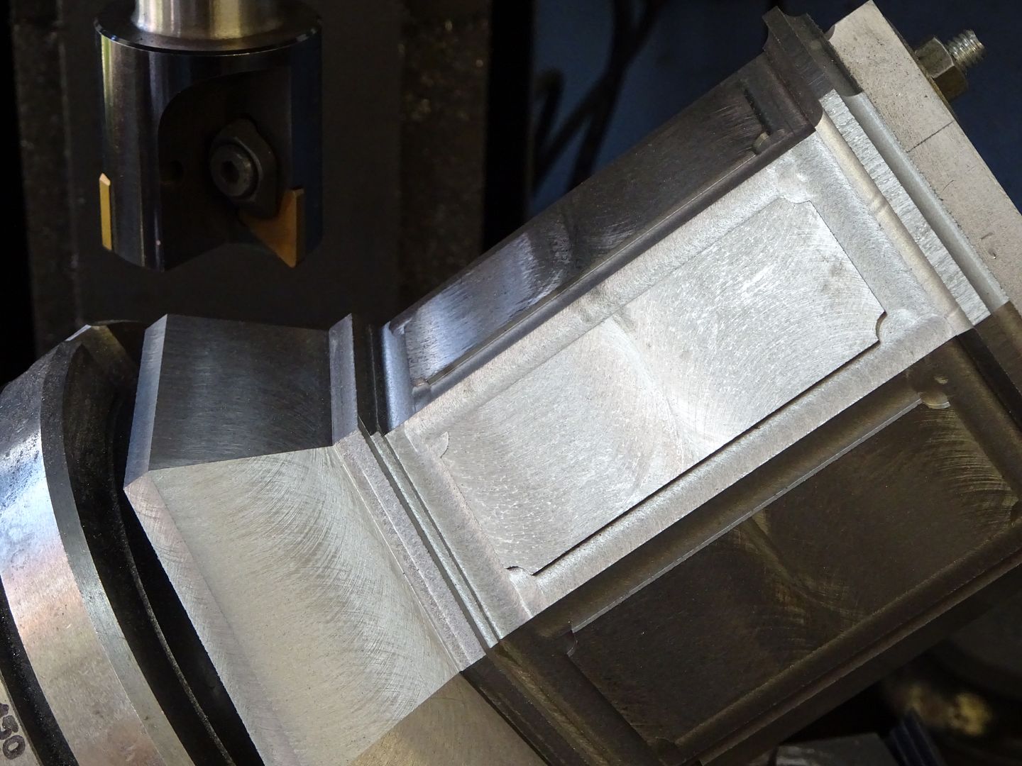
Other decorative options may be easier to machine, something like a raised rectangular panel with a 1/4 circle out of each corner is easy enough to mill and looks acceptable.

DSC02013_zpspiq2sjhj.jpg
 
This isn't Dave, it's his son, Andrew, writing from Telford. I'm visiting. I'm still pondering how to do those covers! Would anyone be kind enough to scan the relevant page of the Jan 1983 EIM article for me?

-Andrew UK
 
Hi Charles, your comment, "The parallel motion is quite different. I have not seen that arrangement of the linkage above the beam before. Actually, I am not even sure it is parallel motion."
The short linkage is one half of the radius of the beam end for the piston rod. The tangential alignment is directly over the cylinder axis, so the con-rod end at the piston rod describes an approximate straight line by the compensation of the swing of the short linkage on the curve of the beam end.
It was a "patent beater" arrangement. - Because Thomas Boulton wanted loads of licence money to use James Watts patented parallel motion and crank. - Or so I understand?
Some one will correct me I am sure.
Plot one and see...?
K2
 
Back
Top