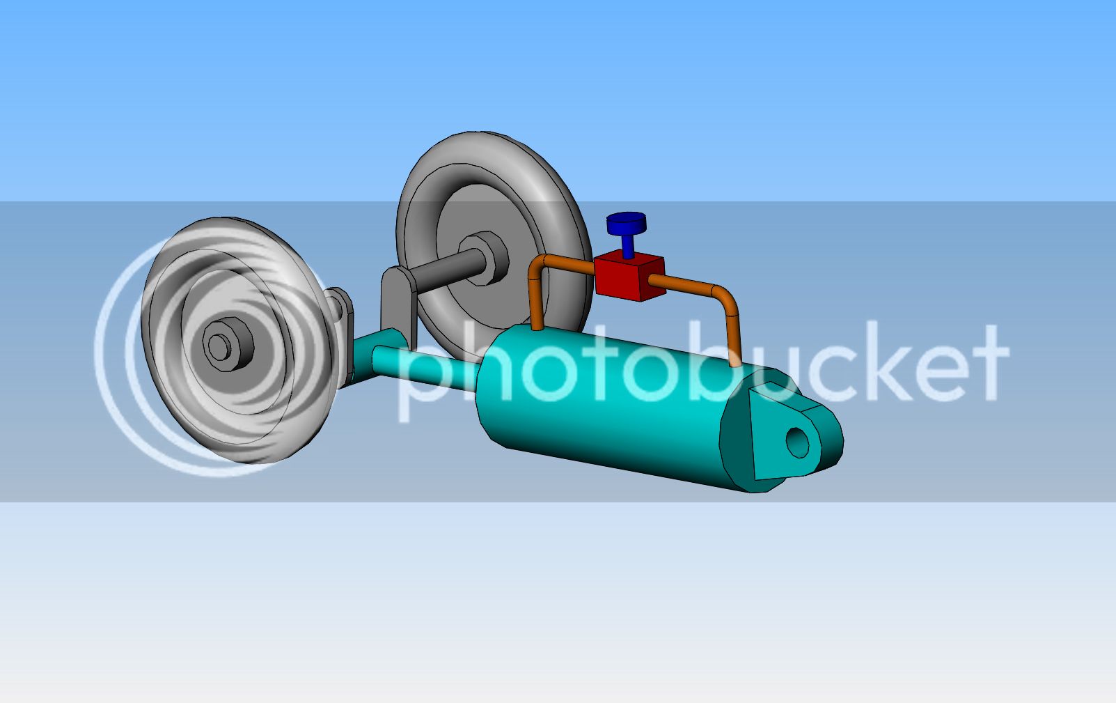
In 50 years of designing machines and mechanical devices of all kinds, I kind of thought that I had "seen it all" in terms of "neat mechanical devices". Last week while researching a machine that is already on the market, I seen something which just blew me away. This is an absolutely brilliant solution to controlling the speed of a rotating shaft. I would have never thought of this in a hundred years. The machine in question runs down an inclined plane, under the force of gravity---but---the speed at which it rolls must be controlled, so that it doesn't "run away" under the force of gravity. The axle which the wheels are attached to, is actually shaped like a crankshaft. The blue cylinder has the rod end mounted on the "throw" of the axle/crankshaft. The clevis at the rear of the cylinder is attached to the framework which supports the rotating axle/crankshaft, in a manner which allows it to pivot. The cylinder is filled with hydraulic oil on both sides of the piston. As the wheels and axle rotate, the axle/crankshaft drives the piston rod in and out of the cylinder body, forcing the oil back and forth from one end of the cylinder to the other. The needle valve fitted to the line which runs to both ends of the cylinder can be adjusted to control how freely the hydraulic fluid can pass from one end of the cylinder to the other,thus making it possible to control the speed at which the axle can rotate. Granted, I don't think it would be a totally constant "drag effect" on the axle, as there would be a bit of a "dead spot" as the piston went over "dead center" at both ends of the stroke, but overall, during the greatest linear part of the stroke in both directions the speed would definitely be controlled. There are probably 25 other ways of achieving the same result to "control speed", but this is the first time I have ever seen this. It is so uniquely "neat" that I just had to show it.---Brian


![MeshMagic 3D Free 3D Modeling Software [Download]](https://m.media-amazon.com/images/I/B1U+p8ewjGS._SL500_.png)


