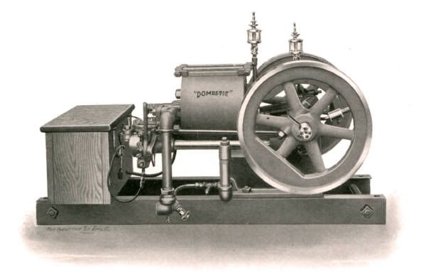
Well with the Benson out of the way I suppose I should start to write up the next project which is as the title says a half scale model of a Domestic Stovepipe or frost proof hit and miss engine, the name comes from the fact that the hopper is sheet metal not cast which was prone to crack if left in a barn or around the farm full of water in cold weather. This is an old catalogue picture of what the finished engine should look like
This kit is one of the original Dick Shelley produced ones but you can now buy them from Bob Herder. As you can see there are quite a few pieces and being half scale its quite a hefty model, the parts as shown below weigh it at about 55lbs. To get an idea of size the flywheels finish up at 7.2 dia.
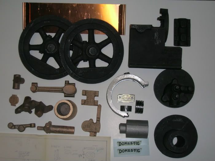
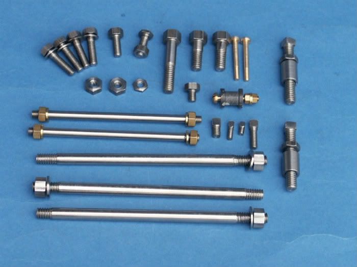
As is my usual way I have several projects on the go at the same time and started to do the odd little bit of this engine between other things. Rather than tackle one of the castings first I thought I would get some of the smaller items out of the way so decides to make rather than buy all the fixings. The drawings specify 1/4x20, 10-24 and 5-40 for most of the threads so I substituted ¼ Whitworth, 2BA and 5BA and came out with this little pile.
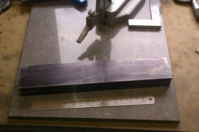
Once I started properly the first item to get worked on was the main engine casting which is really the crankcase. A light skim was taken off the upper surfaces to give a stable base so that the casting could be clamped upside down and the foot machined flat, the edges trued up so future references could be taken from them and at the same time a recess cut to take a brass plate to form the fuel tank within the base.
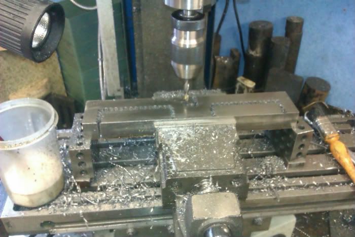
With that done the casting was bolted right way up to the mill table and the flat pockets to take the bearing caps machined and bolt holes to hold them tapped. The bearing caps were also machined at this time so they would be ready for when the bearings needed boring.
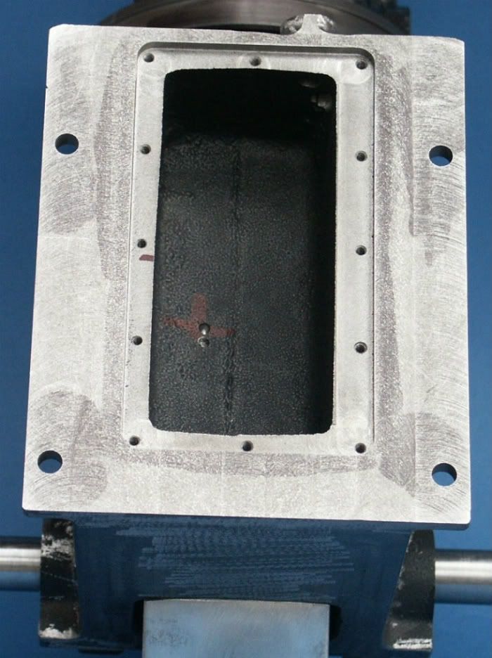
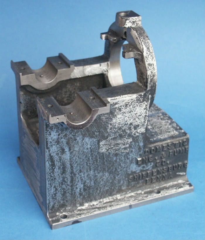
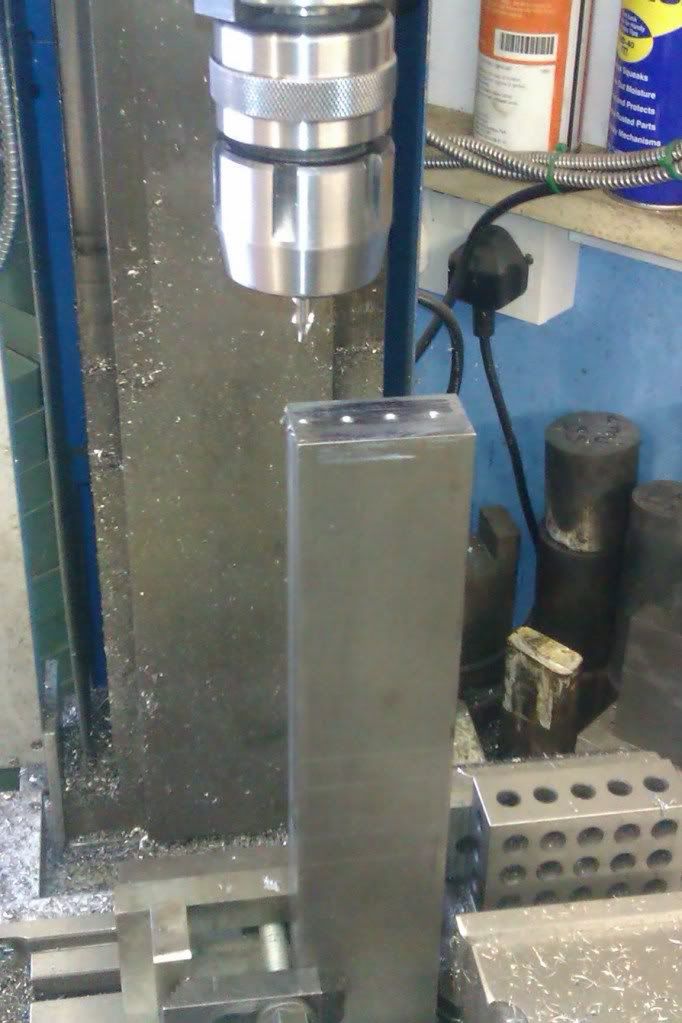
The casting was then upended and the flange that holds the cylinder faced, bored and the fixing holes drilled to the correct PCD using the DRO to work out the locations.
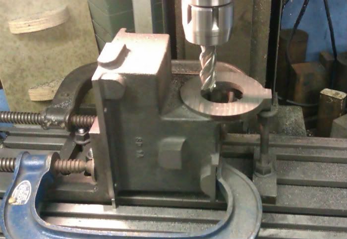
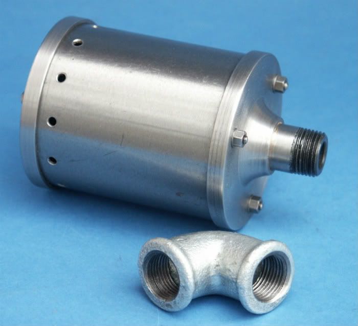
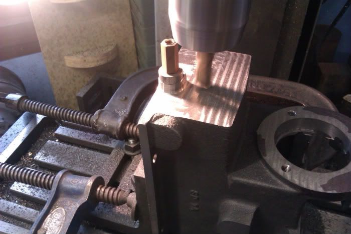
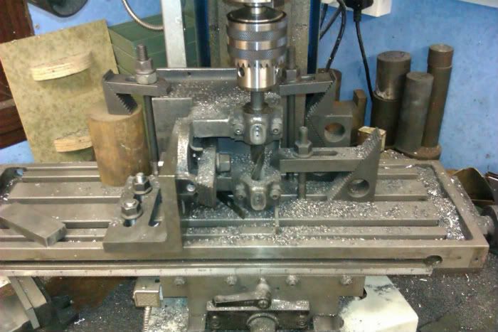
Due to the way the base pattern is split the fuel feed boss needs to be machined round . I free handed it with a ½ slot drill that had had the corners rounded off so it left a cast fillet at the base of the boss. As a guide to the freehand cutting the bit of hex stock is screwed into the pipe thread and an ali ring left loose on the shank, as the edge of the mill touches the ali it starts to turn, thats when you stop feeding in the cutter and move a little further round the boss.
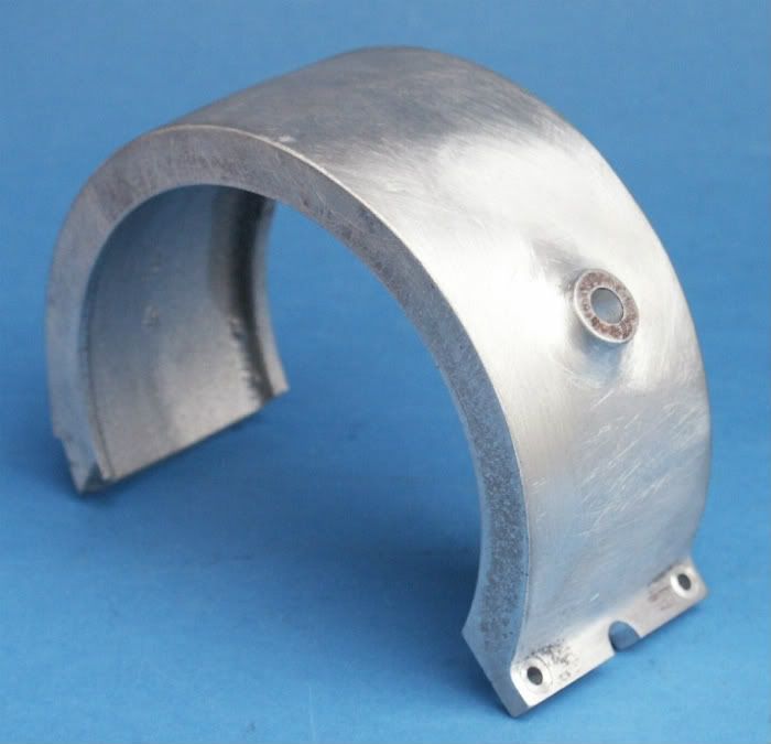
The mould halves were also a bit out of line so the casting was shimmed slightly off true and the end milled flat, the effect of the shim is to maintain the draught angle. The surface will be textured a bit later so it looks cast.
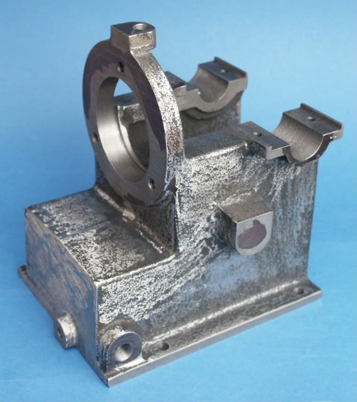
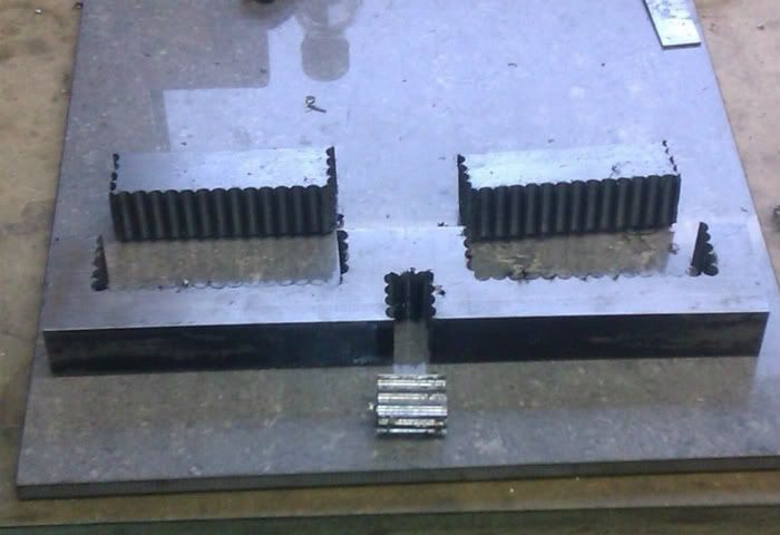
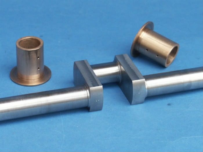
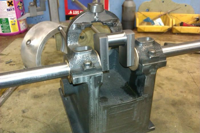
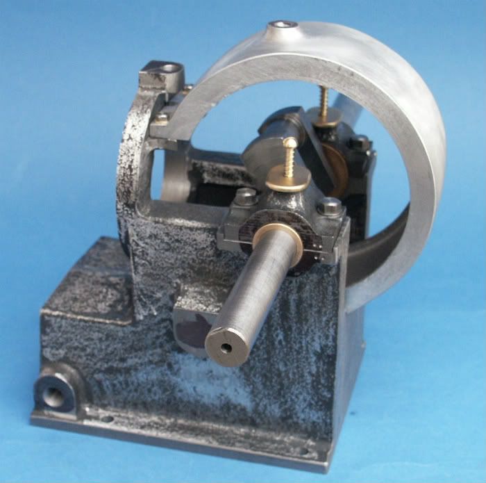
The last major item for now on the base is to bore the two bearing housings so the bearing caps were fixed on with socket screws for now and the casting set on its side. The centre point was then picked out and the majority of the waste drilled out before changing to a boring head to take it out to 0.812 ready to accept the bearings.
And here it is with a few other surfaces faced to size, holes added and you can just see the two little pins in the bottom of the bearing housings that stop the bearings rotating.
 .
.
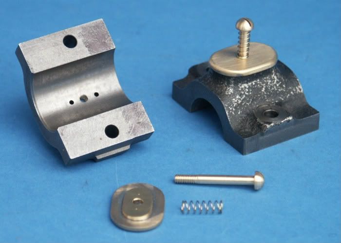
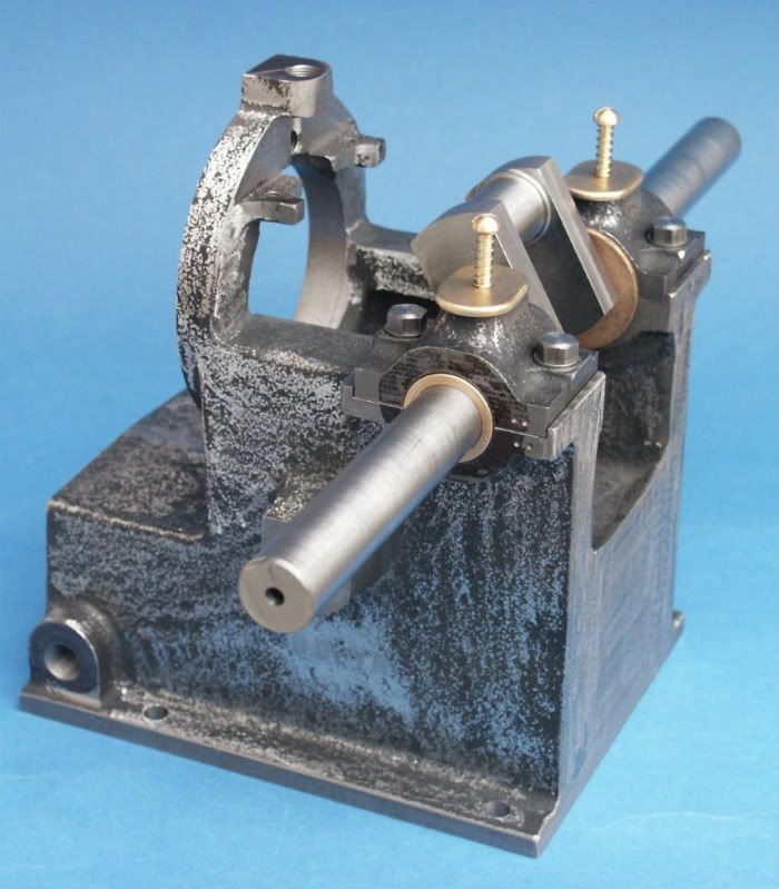
The bearings were finished off with some brass covers to the oil boxes with springs & screws to keep them in place
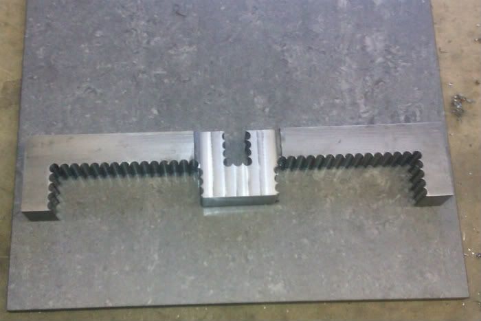
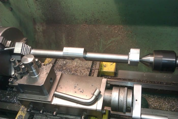
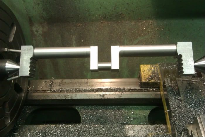
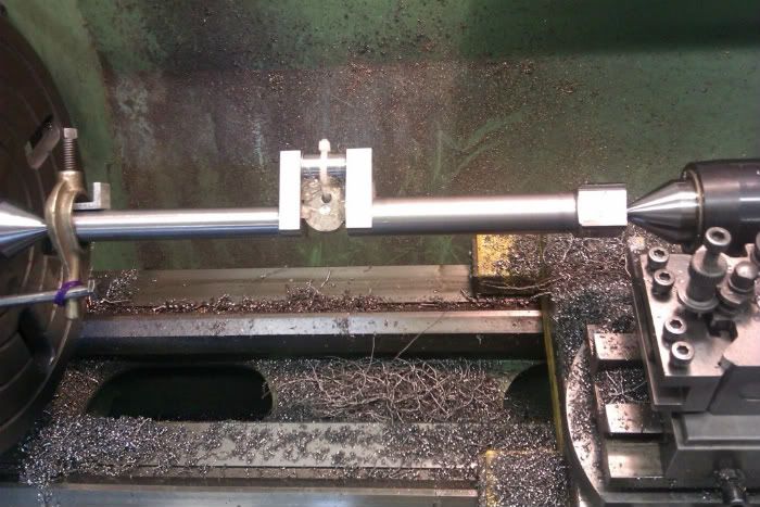
That will do for now, next I will deal with the crankshaft.
Jason
This kit is one of the original Dick Shelley produced ones but you can now buy them from Bob Herder. As you can see there are quite a few pieces and being half scale its quite a hefty model, the parts as shown below weigh it at about 55lbs. To get an idea of size the flywheels finish up at 7.2 dia.
As is my usual way I have several projects on the go at the same time and started to do the odd little bit of this engine between other things. Rather than tackle one of the castings first I thought I would get some of the smaller items out of the way so decides to make rather than buy all the fixings. The drawings specify 1/4x20, 10-24 and 5-40 for most of the threads so I substituted ¼ Whitworth, 2BA and 5BA and came out with this little pile.
Once I started properly the first item to get worked on was the main engine casting which is really the crankcase. A light skim was taken off the upper surfaces to give a stable base so that the casting could be clamped upside down and the foot machined flat, the edges trued up so future references could be taken from them and at the same time a recess cut to take a brass plate to form the fuel tank within the base.
With that done the casting was bolted right way up to the mill table and the flat pockets to take the bearing caps machined and bolt holes to hold them tapped. The bearing caps were also machined at this time so they would be ready for when the bearings needed boring.
The casting was then upended and the flange that holds the cylinder faced, bored and the fixing holes drilled to the correct PCD using the DRO to work out the locations.
Due to the way the base pattern is split the fuel feed boss needs to be machined round . I free handed it with a ½ slot drill that had had the corners rounded off so it left a cast fillet at the base of the boss. As a guide to the freehand cutting the bit of hex stock is screwed into the pipe thread and an ali ring left loose on the shank, as the edge of the mill touches the ali it starts to turn, thats when you stop feeding in the cutter and move a little further round the boss.
The mould halves were also a bit out of line so the casting was shimmed slightly off true and the end milled flat, the effect of the shim is to maintain the draught angle. The surface will be textured a bit later so it looks cast.
The last major item for now on the base is to bore the two bearing housings so the bearing caps were fixed on with socket screws for now and the casting set on its side. The centre point was then picked out and the majority of the waste drilled out before changing to a boring head to take it out to 0.812 ready to accept the bearings.
And here it is with a few other surfaces faced to size, holes added and you can just see the two little pins in the bottom of the bearing housings that stop the bearings rotating.
The bearings were finished off with some brass covers to the oil boxes with springs & screws to keep them in place
That will do for now, next I will deal with the crankshaft.
Jason


![DreamPlan Home Design and Landscaping Software Free for Windows [PC Download]](https://m.media-amazon.com/images/I/51kvZH2dVLL._SL500_.jpg)


")