G-Code record

Home Model Engine Machinist Forum

Help Support Home Model Engine Machinist Forum:

This site may earn a commission from merchant affiliate links, including eBay, Amazon, and others.

Mike Ginn

Well-Known Member
HMEM Supporting Member
Joined
Mar 5, 2020
Messages
343
Reaction score
145
Location
UK
Guys
I have just generated G-Code using CAMBAM and there are 75,000 lines. Is this a record? I have to say I was shocked. I am now sitting down with a glass of wine deciding the best way to modify the tool path. The main issue is the 0.3mm cutter and area clearance. I have to stay with the 0.3 cutter but introducing say a 6mm to remove the bulk of the Al would seem to be the way forward.
Maybe a second glass!
Mike
 
I did over 100,000 yesterday adaptibe clearance with a 3mm cutter then 3D with 2.0mm ball ended using 0.1mm stepover. used F360


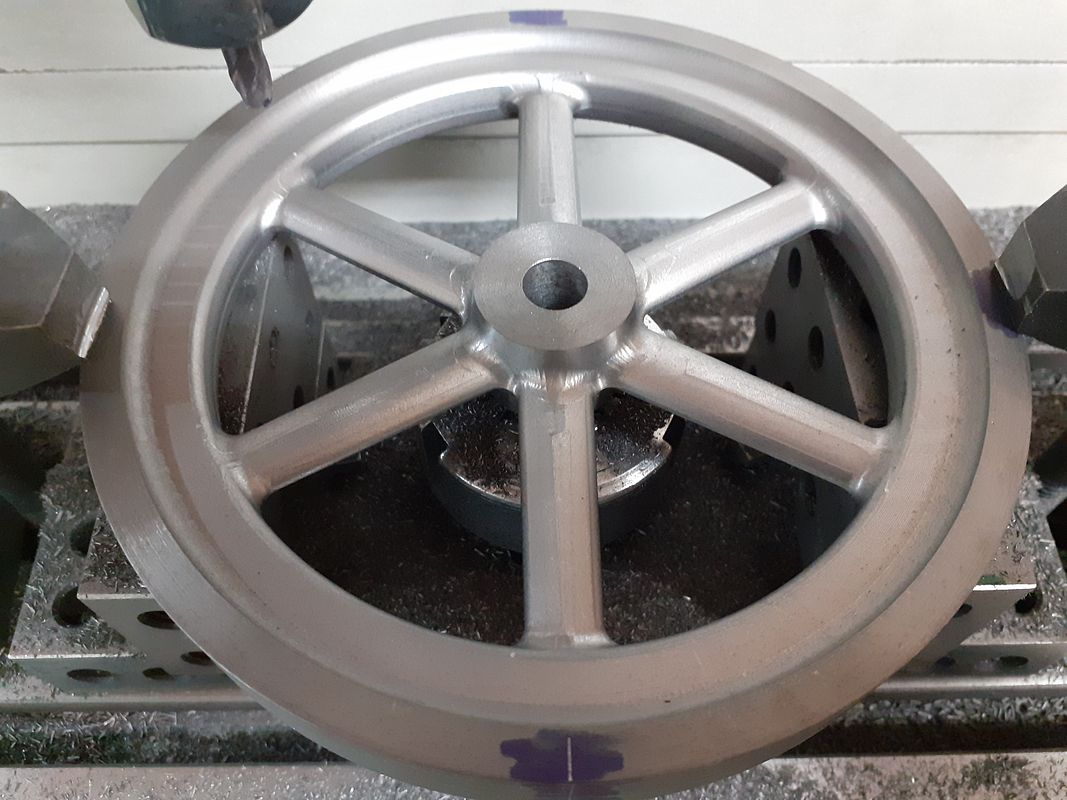
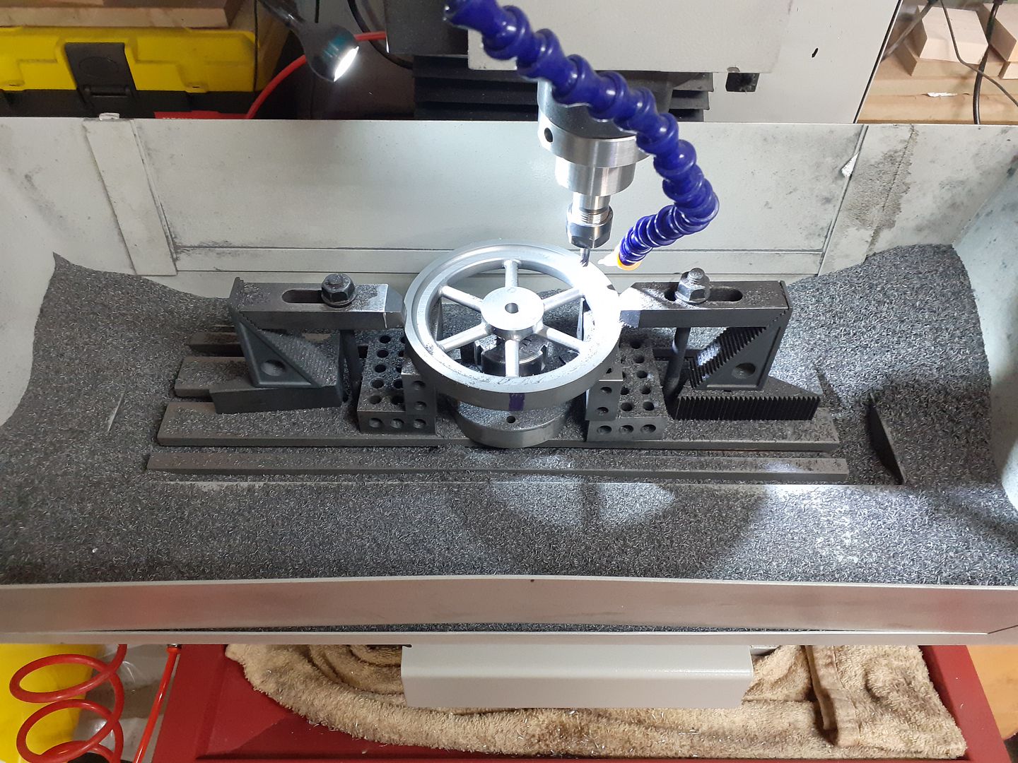
This flywheel was approx 150,000 per side and there were two on the engine

 
Last edited:
Guys
I have just generated G-Code using CAMBAM and there are 75,000 lines. Is this a record? I have to say I was shocked. I am now sitting down with a glass of wine deciding the best way to modify the tool path. The main issue is the 0.3mm cutter and area clearance. I have to stay with the 0.3 cutter but introducing say a 6mm to remove the bulk of the Al would seem to be the way forward.
Maybe a second glass!
Mike
A 0.3 mm cutter? I find that more impressive, than the number of code lines. :)
How long can you use that small cutter, before it wears out? Seems to be no point in not using a bigger cutter for the roughing first.
I assume you need to change the tool in any case. Due to wear or because you use different sizes.
I am curious to see what you machine with a 0.3 mm cutter and how to keep it from breaking off, the moment you look angry?
 
How did you get the spokes aligned with the machine position after flipping the part?

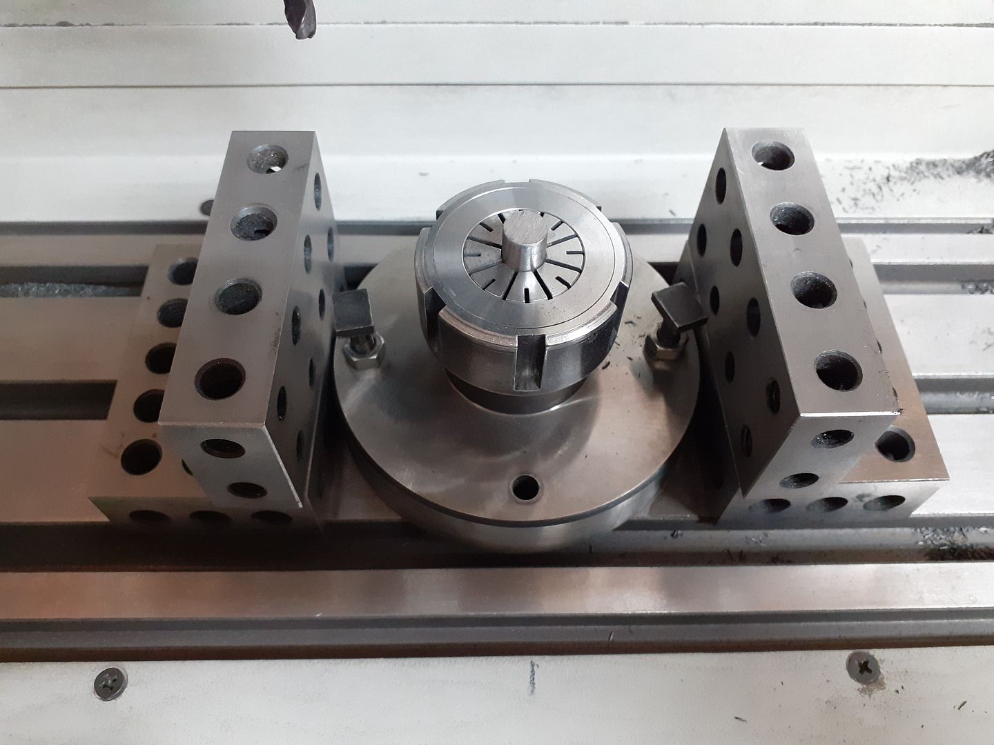
There is a short length of drill rod held in a flange mounted ER32 Collet under the flywheel to keep it centred

20210117_133641.jpg


And a scribed line on the rim to line it up with when turned over to do the other side

20210117_133105.jpg


20210119_133651%5B1%5D.jpg
 
A 0.3 mm cutter? I find that more impressive, than the number of code lines. :)
How long can you use that small cutter, before it wears out? Seems to be no point in not using a bigger cutter for the roughing first.
I assume you need to change the tool in any case. Due to wear or because you use different sizes.
I am curious to see what you machine with a 0.3 mm cutter and how to keep it from breaking off, the moment you look angry?
I just finished hand tapping 8 m 3 x .5 holes in my engine mount blocks the dog gone taps would not thread into known m3x .5 tapped holes now after tapping the mount holes they thread into the test part. I even tried m 3x.5 screws fist . I don’t have a drill guide yet but that’s the next thing to make as I have a number of holes to drill and tap . I was tempted to run the tap in with my drill driver but I don’t think the clutch slips soon enough and I didn’t want to deal with a broken tap they are don so I can now start engine assembly .
byron
 
A 0.3 mm cutter? I find that more impressive, than the number of code lines. :)
How long can you use that small cutter, before it wears out? Seems to be no point in not using a bigger cutter for the roughing first.
I assume you need to change the tool in any case. Due to wear or because you use different sizes.
I am curious to see what you machine with a 0.3 mm cutter and how to keep it from breaking off, the moment you look angry?
Hi Timo
The 0.3mm is the flat at the tip of a V engraving cutter. I re-did the tool path using a 6mm cutter for the main pockets and the code reduced to 42000 lines. The design is a 2mm thick name plate for my Wyvern using Al sheet - maybe brass would be better?. I have never cut out a name plate before so it should be interesting. BTW my cut depth is 0.2mm and I am hoping the 10 cutters I have with be sufficient.
I'm really in new territory with this!!
Mike
.
I imagined you are micromachining watchparts with a 0.3 mm square endmill. Or torx bolt heads into titanium screws. :)
Post a photo of the result when done.
 
Last edited:
A 0.3 mm cutter? I find that more impressive, than the number of code lines. :)
How long can you use that small cutter, before it wears out? Seems to be no point in not using a bigger cutter for the roughing first.
I assume you need to change the tool in any case. Due to wear or because you use different sizes.
I am curious to see what you machine with a 0.3 mm cutter and how to keep it from breaking off, the moment you look angry?
Hi Timo
The attached shows the name plate for my Wyvern. The pocket is 0.6mm deep on 1.2mm brass of unknown spec but soft. The cutter was a 0.3mm 10deg engraving tool which I got on eBay as a pack of 10. I routed the outline using a 6mm slot cutter. The holes I CNCed using the 0.3 cutter.
For the right hand plate I loaded the 83,000 lines of code for 12 passes of 0.05mm which took 10 hours with no broken cutter although I did break one in setting up the zero height. I used cutting oil and air gunned the small brass particles about every hour.

The right hand plate is as machined. The left hand plate shows how I will (probably) surface finish. The other option is to spray the pocket with black paint and polish the letters.

The left hand plate shows how I wrecked the plate trying to drill the brass - really not sure what went wrong - I was using a new Dormer drill and then it all went wrong with the 6mm cutter at the other end. I had stopped the program and didn't correctly start it. I used a cutter increment of 0.1mm which worked but I noticed brass deposits on the cutter - hence moving to 0.05mm.
A fun day!
Mike

I designed the outline in AutoCad and exported to CamBan. I inserted the text in CamBan and used the pocket tool to clear the material. I noticed that the enclosed space (as in B) were pocked at the last cycle. I have not used the pocket feature before so it was a surprise! I initially thought that the G-Code was wrong but the tool path was correct. The mill was a KX1
1646321682296.png
 
I use the same type of cutter for aluminum name plates for cars. They do last quite a while, and are pretty cheap in a pack of 10. I commonly use the .012" wide flat end with a 30 degree angle (.3mm), but sometimes a .004" 60 degree one (.1mm). I run them at 29,000 RPM (high speed tool adapted to the side of the main spindle column) with a mist system.
 
I use the same type of cutter for aluminum name plates for cars. They do last quite a while, and are pretty cheap in a pack of 10. I commonly use the .012" wide flat end with a 30 degree angle (.3mm), but sometimes a .004" 60 degree one (.1mm). I run them at 29,000 RPM (high speed tool adapted to the side of the main spindle column) with a mist system.
Thats an impressive speed. My mill only goes to 7000 and I make so few name plates it really isn't worth fixing up a high speed spindle. I don't have mist lub or the means of containing the fluid. On my lathe I have pumped cutting oil but the mill has to make do with a brush and jar!
What cut depth per pass do you use?
Thanks
Mike
 
My mill goes to 7,000 as well, but I do a lot of badges (hobby/side business) so I added a high speed spindle. It is like a Mototool on steroids. I have it and the cooling system hooked up to the same power source with an M08 command to turn them on. I take the spindle off when I am using the factory spindle if it is going to get in the way.

Screen Shot 2022-03-03 at 7.44.24 PM.png

A mist system is great! There is no coolant to collect, it puts out such a fine atomized spay that it basically evaporates as it hits the work/cutter, taking the heat with it. It is pretty much essential for high speed cutters in aluminum to prevent the aluminum from welding to the cutter. An average machining job of 20 minutes uses about a teaspoon of coolant.

I usually machine about .012" depth with the first pass, conventional machining. Then another pass .004" deeper climb cutting. I find that gives a pretty nice finish on the edges. I powder coat the badges after.

Some of what I make to sell.

Screen Shot 2022-03-03 at 7.46.48 PM.png

Powder coated:

Screen Shot 2022-03-03 at 8.06.35 PM.jpg

Screen Shot 2022-03-03 at 7.46.17 PM.png

And coasters to give to friends and family.

Screen Shot 2022-03-03 at 7.48.08 PM.png

Rick
 
Rick
That is very interesting and impressive. I will look into misting - I have never seen the kit for sale so will investigate. I note that you powder coat. Looking at your badges I couldn't see how you achieved the result. Do you powder coat the blank then machine. If not how do you pick out the image? Looking at the last image (some have scrubs) it looks like the words are depressed into the blank but still powder coated?
Is your high speed spindle a small hand held electric drill - seems to be too higher speed for that. I have an air drill which is near that speed but the bearings are not good enough and it is too noisy.
Thank you for the info - I have never conversed with anyone who has made such badges - much appreciated.
Mike
 
Hi Mike,

The high speed spindle is the 800 FME from this place:

spindle

I've used it for years and it is a really good unit. I've replaced the brushes once. With 1/8" milling cutters I dial it down to around 12,000 RPM, but for the pointed cutters I let it rip at full speed, 29,000 RPM. I've used it with cutters up to 1/4" in aluminum, but take light cuts with that since I don't want to put too much load on the bearings.

Most of the badges and coasters I make, I do the CNC engraving, then powder coat and bake it. Then I sand off the powder coat leaving it in all the machined engravings. Then a clear powder coat over the whole thing. The black ones are a little different and more challenging. I powder coat the whole badge after machining, bake it, then fill in the letters/graphic with the orange (very tricky to do) and bake it again.

The mist setup I use is the Fogbuster from Little Machine Shop; other places probably sell it or an equivalent. It has a large container that the air pressurizes to about 12psi, the coolant is forced out to the nozzle where an additional air supply atomizes the coolant. You are supposed to adjust it so that you barely see any mist, but sometimes I'll run it a bit more than that just to be sure. But even with that it doesn't actually pool the coolant anywhere. And the Kool Mist coolant I use is really inexpensive; the one bottle gets diluted to the point where it will probably outlast me.

The plates that you machine do take a lot longer since you are machining away all the material and leaving the letters, where I tend to machine only the letters. I've done your style, but try not to for the ones I sell since they do take a lot longer. Very nice work though! Oh, just saw that you use a KX1 mill, so the same one I have. Very good unit but hard to find much info on them on the net. I plug the spindle and coolant system into the coolant socket on the side and use M08 to turn them on. I have an electric solenoid on the air supply, so that turns on and off with the CNC'g.

Glad I could be of help,

Rick
 
Hi Rick
Good info. I guess that the mist is water based. I made a decision many years ago to only use cutting oil since it lubricates and doesn't stain. I have found that on machines which are not used daily there are problems with the water based coolant - and of course you must use de-mineralized water.

A question about your KX1. When I purchased it along with Mach3 I was told that I must use XP and a parallel port. I think it is now established that Mach3 will run under W10. At some point I will need to replace the computer (its a very small format tiny tower Dell SX270) and few small computers have parallel ports. More recent KX1 used USB. I could get a USB to parallel convertor but I was told that such a set-up doesn't work correctly - timing issues?

I'm not sure if a USB interface is available for the KX1 - UK support is non-existing?

I would really appreciate details about your setup.

Many thanks

Mike
 
Yes, the coolant is water based, but that doesn't seem to be an issue. From their website: "Kool Mist will not cause corrosion, buildup, dermatitis, rancidity or objectionable odors. Properly diluted with water Kool Mist does not create rust or stains on machined parts". I can confirm that it doesn't stain or rust, maybe because so little of it actually lands on the part or table.

My KX1 did come with the USB setup. I have a CNC router that I made that uses Mach3 with a Windows7 computer with the parallel port. When I had to replace the computer a while ago I found that computer stores wanted to sell me something new and didn't seem to understand when I told them it has to be Windows7 and have a parallel port on the mother board. "Our adapters work fine" "you want something with a lot more memory for future expansion" "Window10 is far better". I found a place that sold refurbished computers and got exactly what I wanted. But if I ever need a replacement it will be more of an issue as time goes on.

KX1 support is pretty much non-existent as far as I've found. I did contact Little Machine Shop recently when I was having an issue (that turned out to be with the Mach3 setup, not the machine) and they got back to me right away, so maybe ask them what they know. But I did get one of the last, or the very last, KX1 they sold and they don't carry them any more. They do have a lot of spare parts and circuit boards for them so maybe they know something about the USB situation.

Rick
 
Mach3 has not been supported for quite a few years now. That doesn't mean that it suddenly stops working, of course, but as already said it will not run with W10. One reason is that newer PCs just do not have parallel ports (and again, as already said, USB to parallel "converters" mess up pulse timing and are not usable in this situation). The other reason is that the Mach3 parallel port driver is 32-bit only and does not work with W10 64-bit, even if installed on a motherboard with a parallel port.

Probably the easiest way to sort this is by using something like the UC100 device from CNCdrive. This looks a bit like a USB-parallel port adapter but is actually much more sophisticated as it offloads a lot of the pulse generation and timing functions from the PC which can improve overall performance. It only needs a USB port on the PC, and has a parallel port socket into which your existing cable will plug. CNCdrive provide a plug-in that works with Mach3; install that and the UC100 and you're ready to go. You might need a little tweak to the Mach3 settings, and you might even be able to squeeze a bit more speed and/or acceleration out of it, although that is more likely to be relevant with a CNC router than a mill.

One important thing to remember is that the KX1 and similar machines don't use anything exotic by way of electronics on the CNC side. It's mainly standard bits and pieces. That means that you don't necessarily have to replace any one item with an exact replacement; there is probably a newer, cheaper, and probably better-performing equivalent available.
 
Back
Top