Damn it, when will I learn, that is so annoying when you've just spent a while typing a reply and the computer decides to lock up! :'( :'( :'(
Anyway, most of what I said was probably waffle!
My main points were:
- 3D CAD is definitely the way to go.
- Alibre is good, we use Unigraphics, a leader, if not the leader in 3D CAD and Alibre seems to me to have similar functionality and it's more user friendly, easy to pick up.
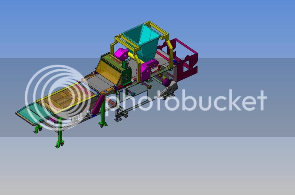
- Main limitation of free version is number of parts in assembly. As Steve says, once you've mastered assembling stuff, you can build sub assemblies and soon put them all together to give you the picture of the completed model. However, as this can't be saved, you won't be able to produce a general assembly drawing of it, just individual parts or sub-assemblies.
- Another limitation is not being able to produce sectioned views ... this is disabled. As model engineers we can probably work around this in most cases.
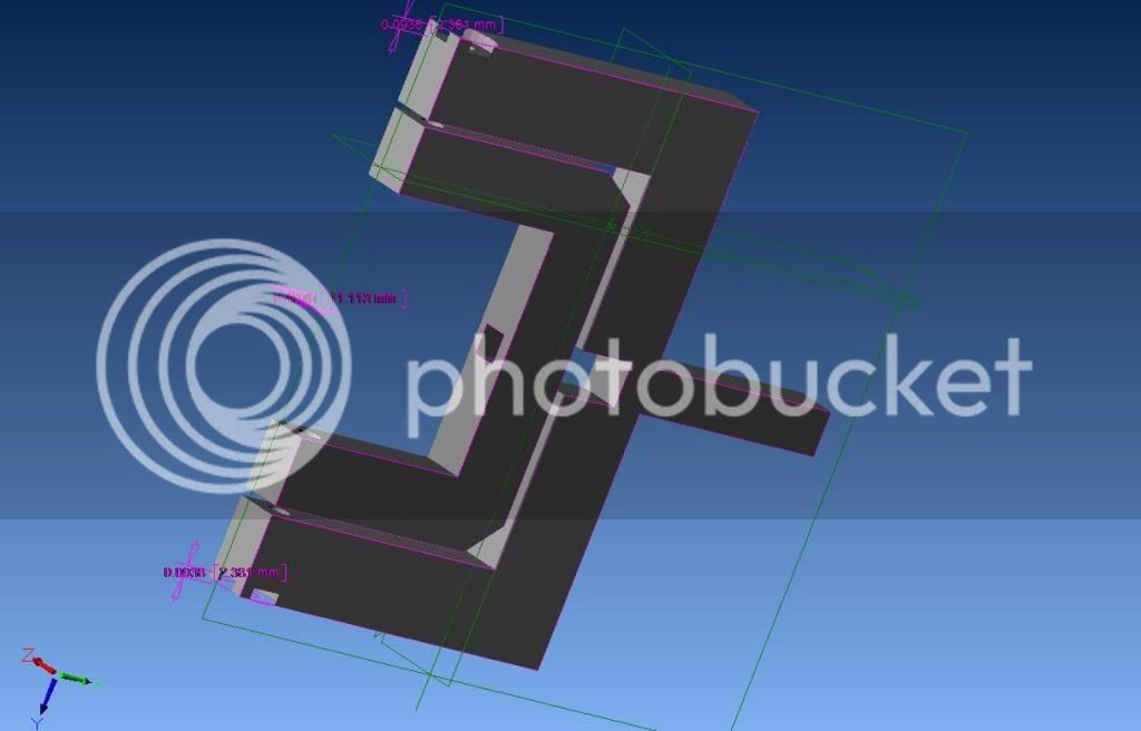
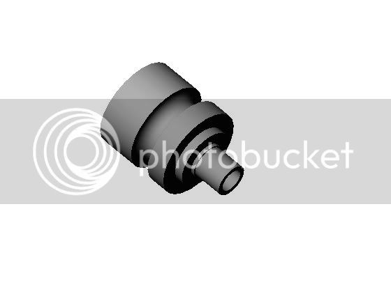
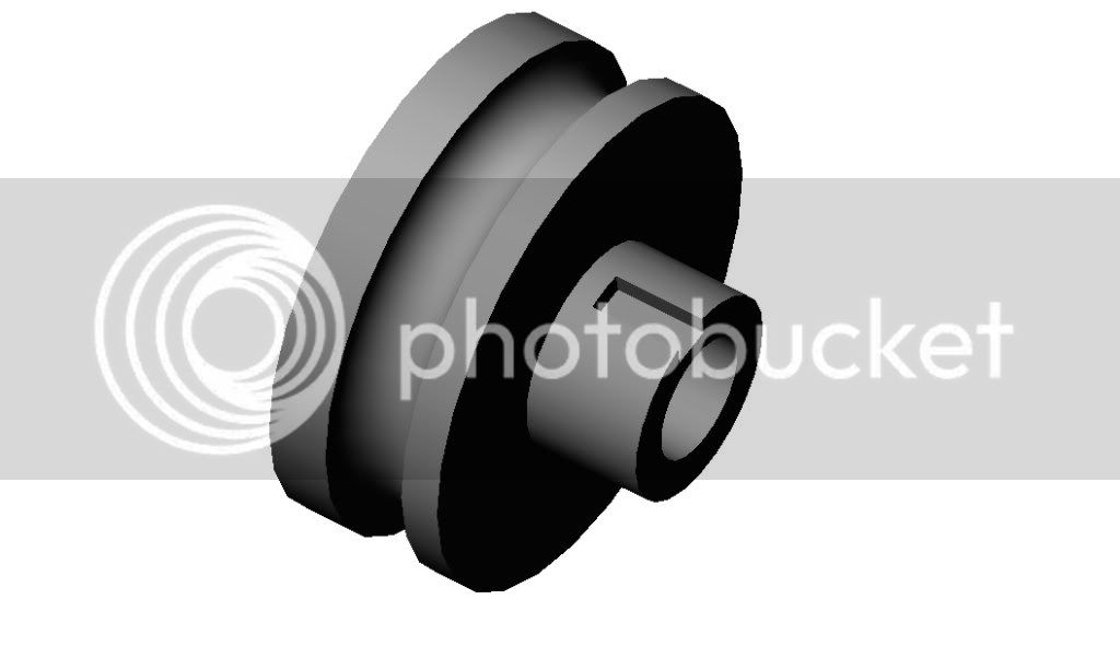
- A good reason for assembling the whole thing is, if you assemble with the correct mating conditions, in turn giving components the correct degrees of freedom, you can "move" a part, i.e. you can spin the flywheel around and see all the rest of the engine working. As Steve, said, not sure if you can get it to do this automatically and run in a loop, but you can see what clearances / interference you have etc.
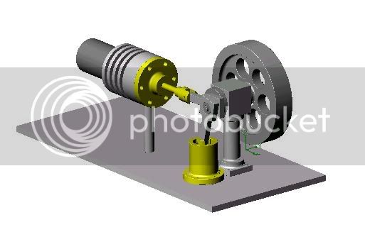
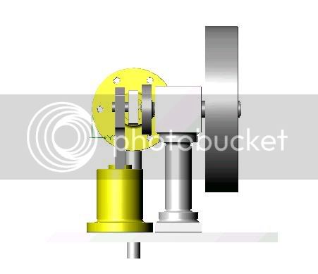
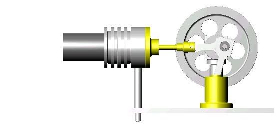
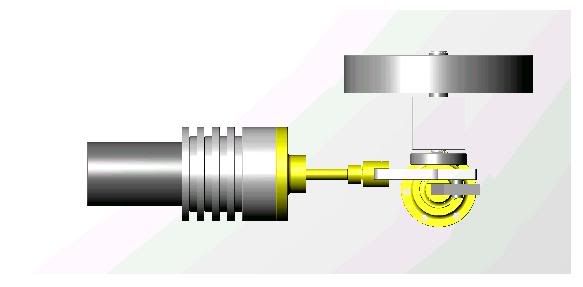
On my Stirling Engine below I inititally had interference between the con rod and cylinder wall, so I lengthened the condrod and other appropriate dimensions until it cleared.
Also attached is a general assembly drawing of my oscillating engine to give an example of a 2D drawing created from the 3D model.
It may sound like a long way around to create everything in 3D first, but trust me, once you get the hang of it (and it's not that hard) it's much better.
Nick


![MeshMagic 3D Free 3D Modeling Software [Download]](https://m.media-amazon.com/images/I/B1U+p8ewjGS._SL500_.png)


![DreamPlan Home Design and Landscaping Software Free for Windows [PC Download]](https://m.media-amazon.com/images/I/51kvZH2dVLL._SL500_.jpg)


