Cutting a cam with radiused flanks

Home Model Engine Machinist Forum

Help Support Home Model Engine Machinist Forum:

This site may earn a commission from merchant affiliate links, including eBay, Amazon, and others.
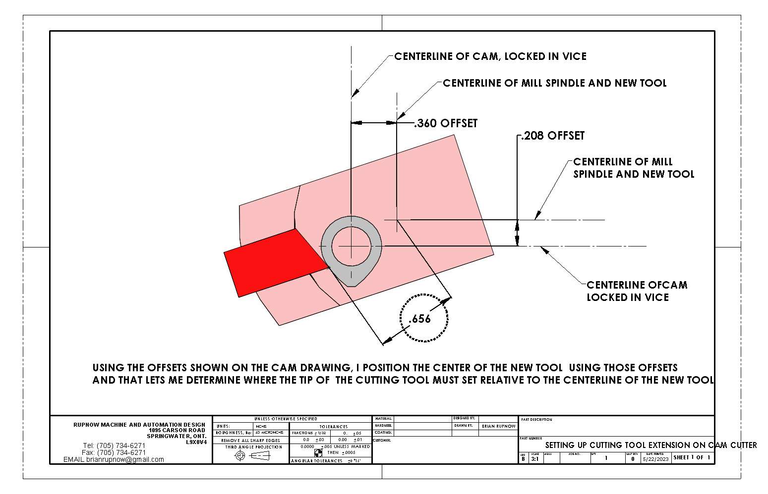
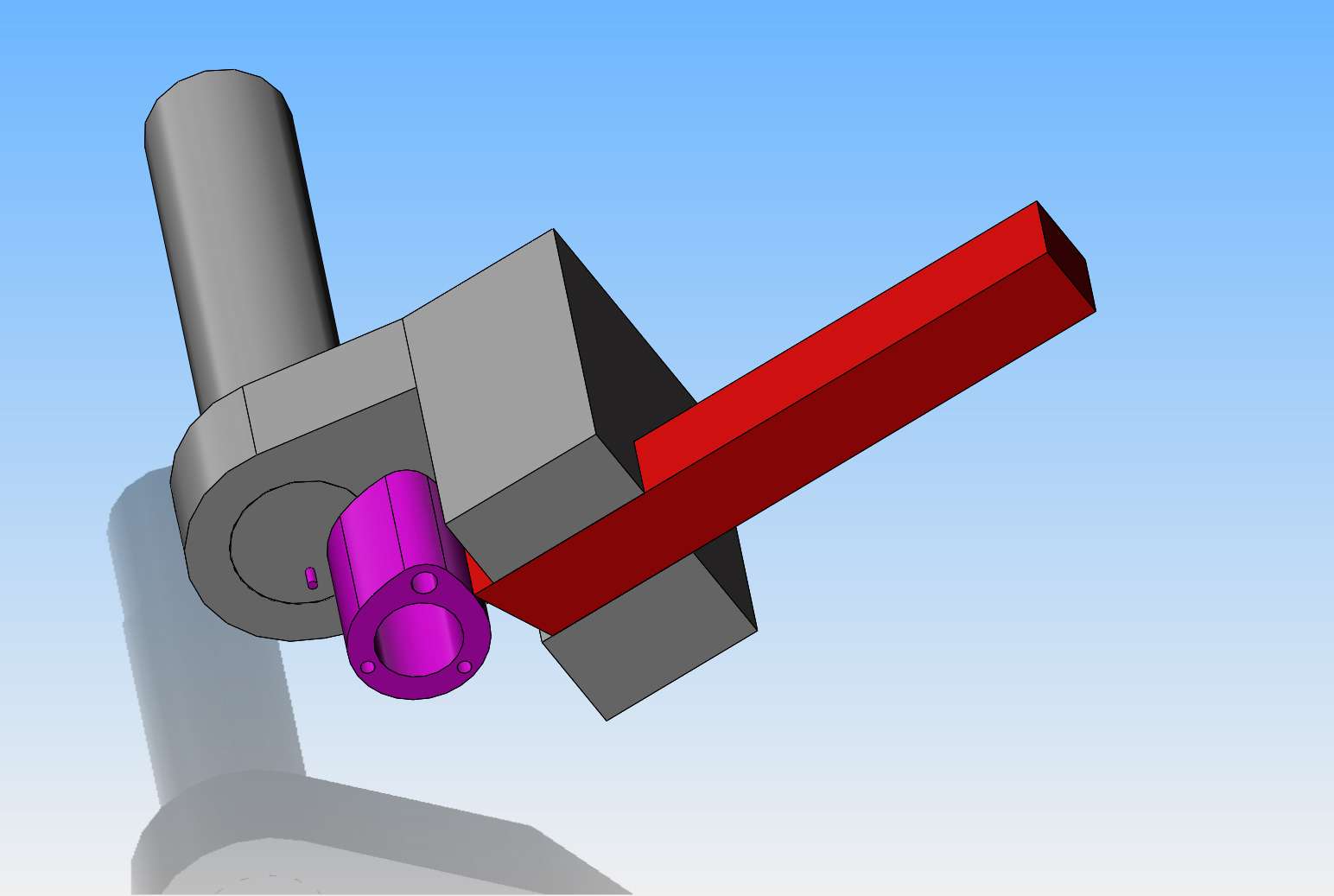
This is how I determine exactly how much of the cutting tool must extend inside the new holder to give the results I want on the cam flanks.
Zv6XRH.jpg
 
Last edited:
This is the way I apply a flank radius to a cam lobe. You have to start with the cam parameters, base circle, lift and duration. These will give you construction lines to draw the nose radius. The valve/lifter clearance has to be accounted for. Let's say it's .005. The flank radius can't be more than the clearance otherwise the valve is starting to open before the proper timing duration. I offset a line from the flank by less than the clearance. In this case .003. I then draw an arc tangent to the nose radius, the base radius and the offset line.
 

Attachments

  • CAM LOBE LAYOUT 2023.pdf
    16.8 KB
Brian,
What would be the timing duration for this lobe?
 
Brian, why do you do the blanks holding the work in a vice and then transfer to the rotary table to do the base radius?

It would be easier to do it all in one setting on the rotary table that way you can be sure to keep the high point of the cam in the right position. You just need to offset the tow positions to do each flank and then do the base radius with the work directly under the spindle.
 
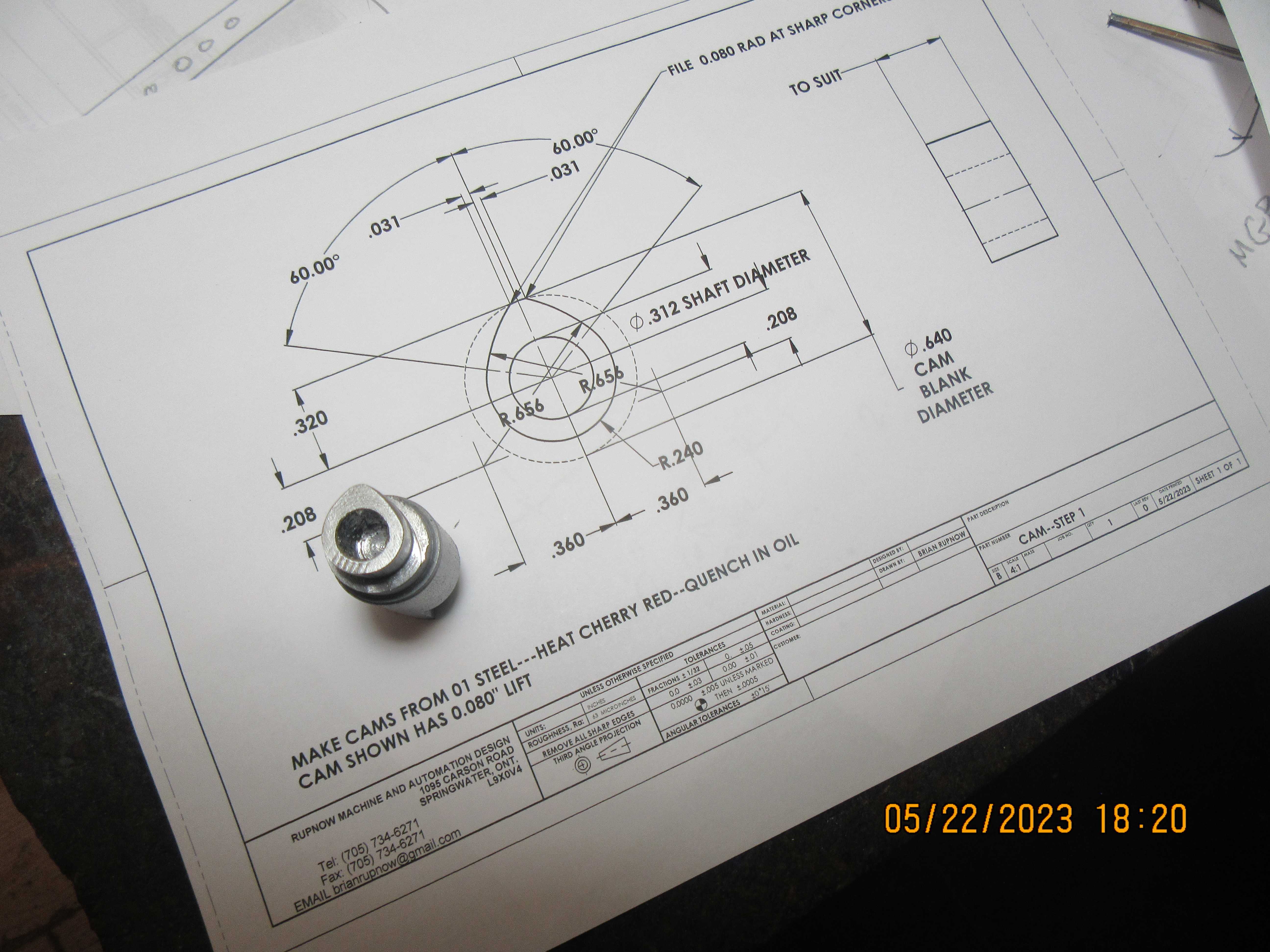
I have spent most of the afternoon correcting the mistakes I made this morning. I have again posted the cam drawing. The cam duration would theoretically be 120 degrees at the cam, 240 degrees at the crankshaft. It probably could be machined totally held in the rotary table chuck, I just never thought of doing it that way.
 
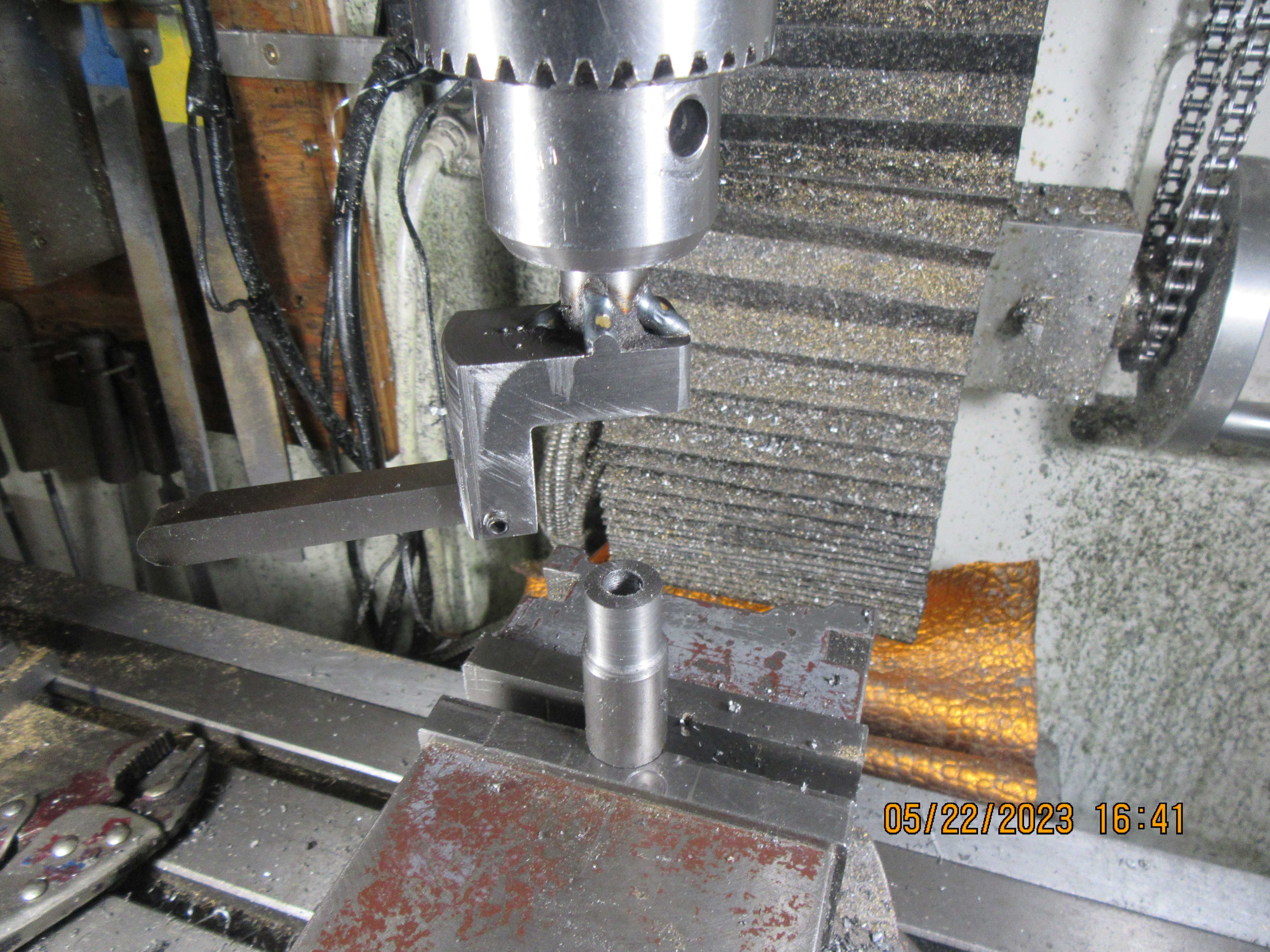
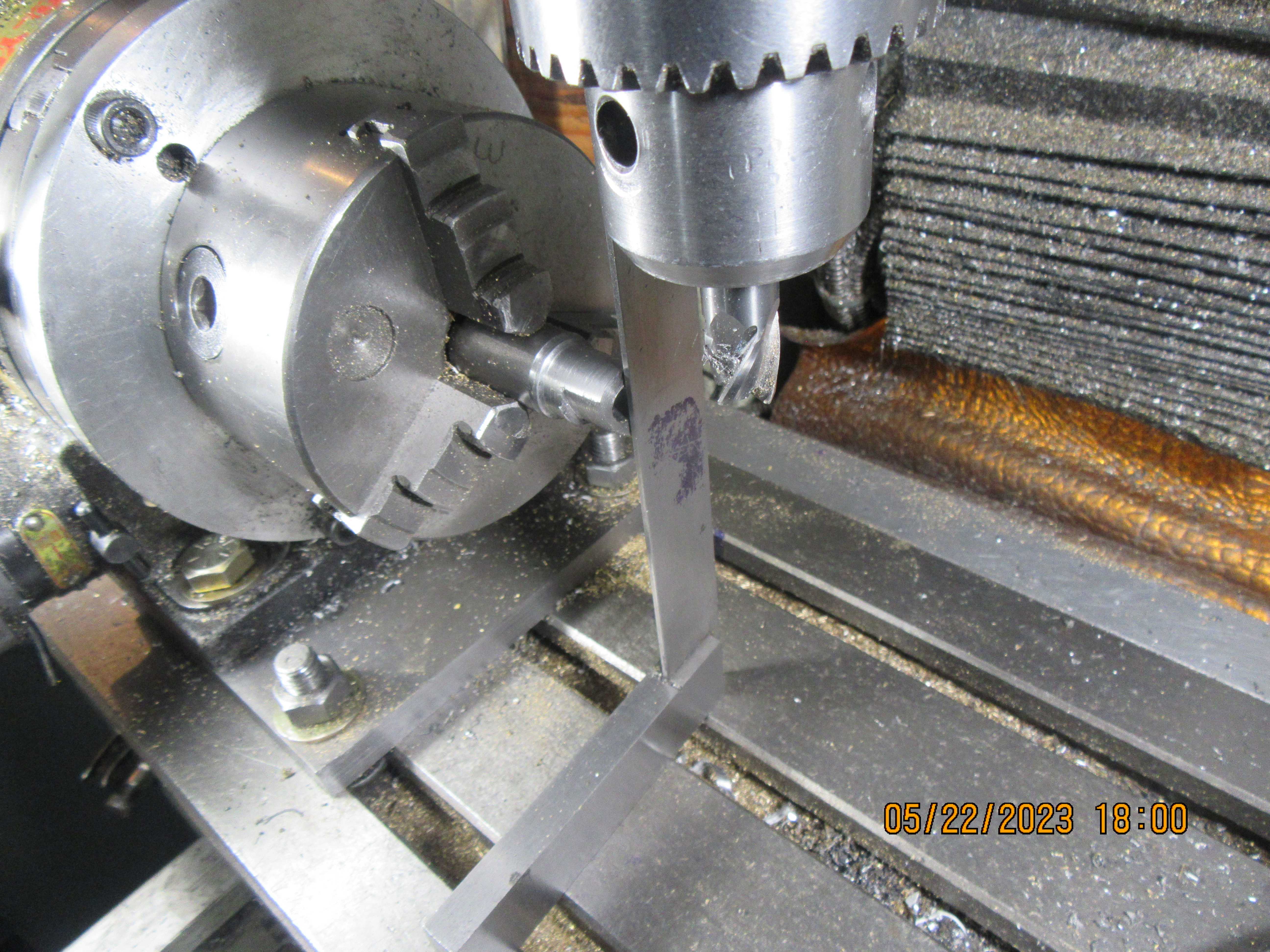
Here we are, all set up in the mill. The spindle was centered on the cam material, the the table was moved in the x and y axis to match up with the offsets in the drawing of the cam.
D5k7iC.jpg
 
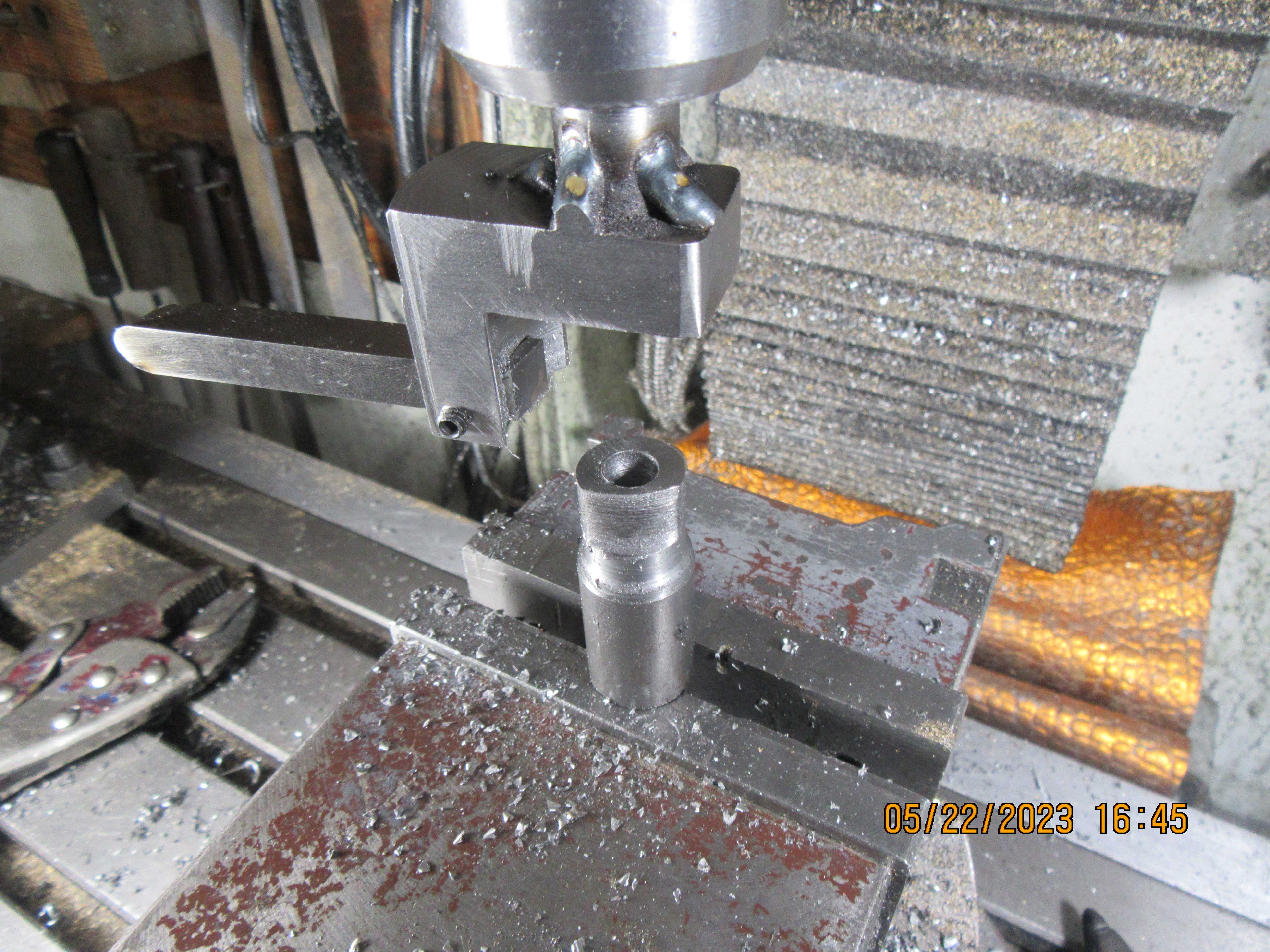
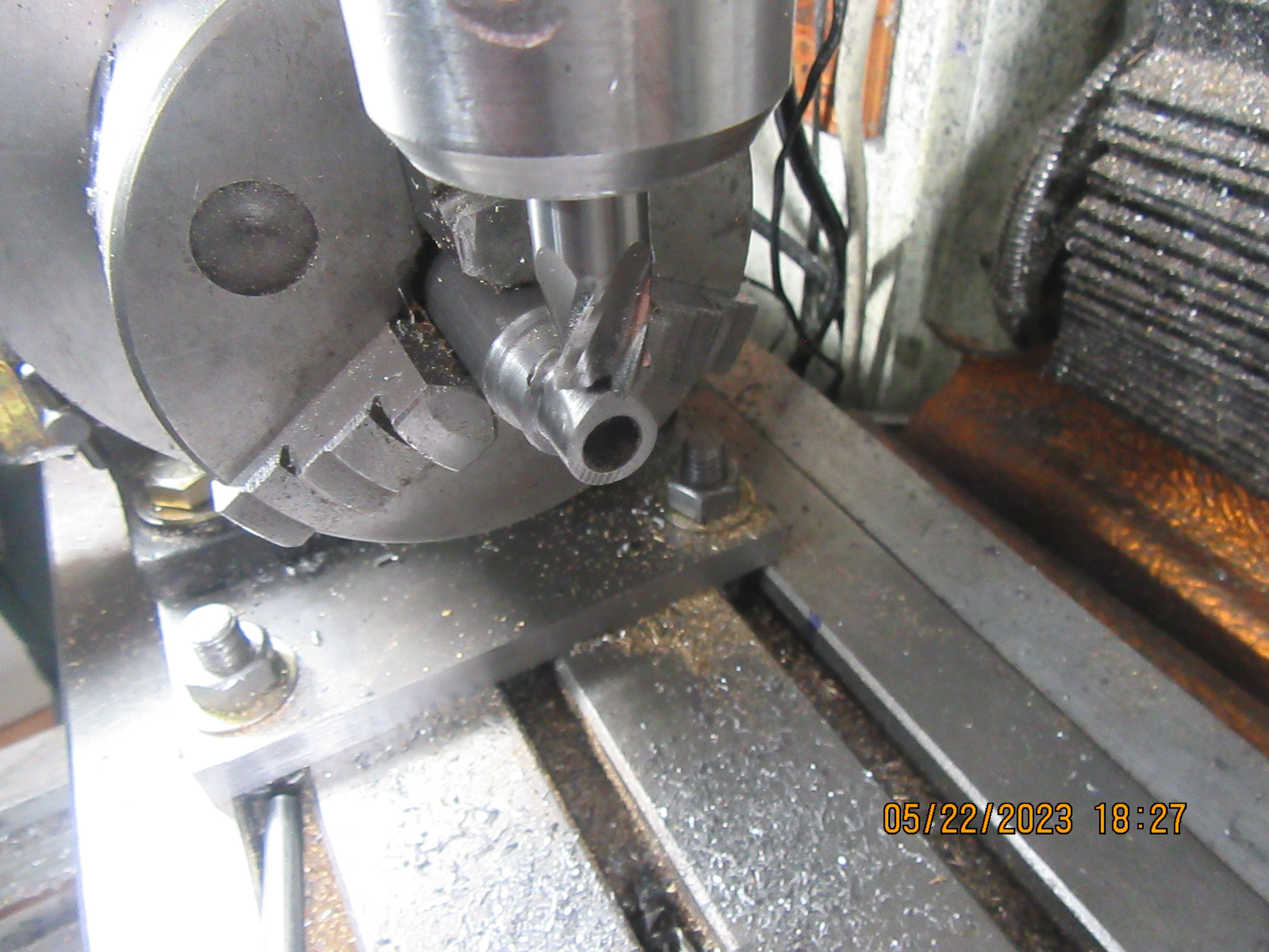
And here we have the first side of the cam cut. I used the manual fine adjustment for the vertical feed, but it went very quickly, took about five minutes to cut one side 0.4" deep.
Xv3EPZ.jpg
 
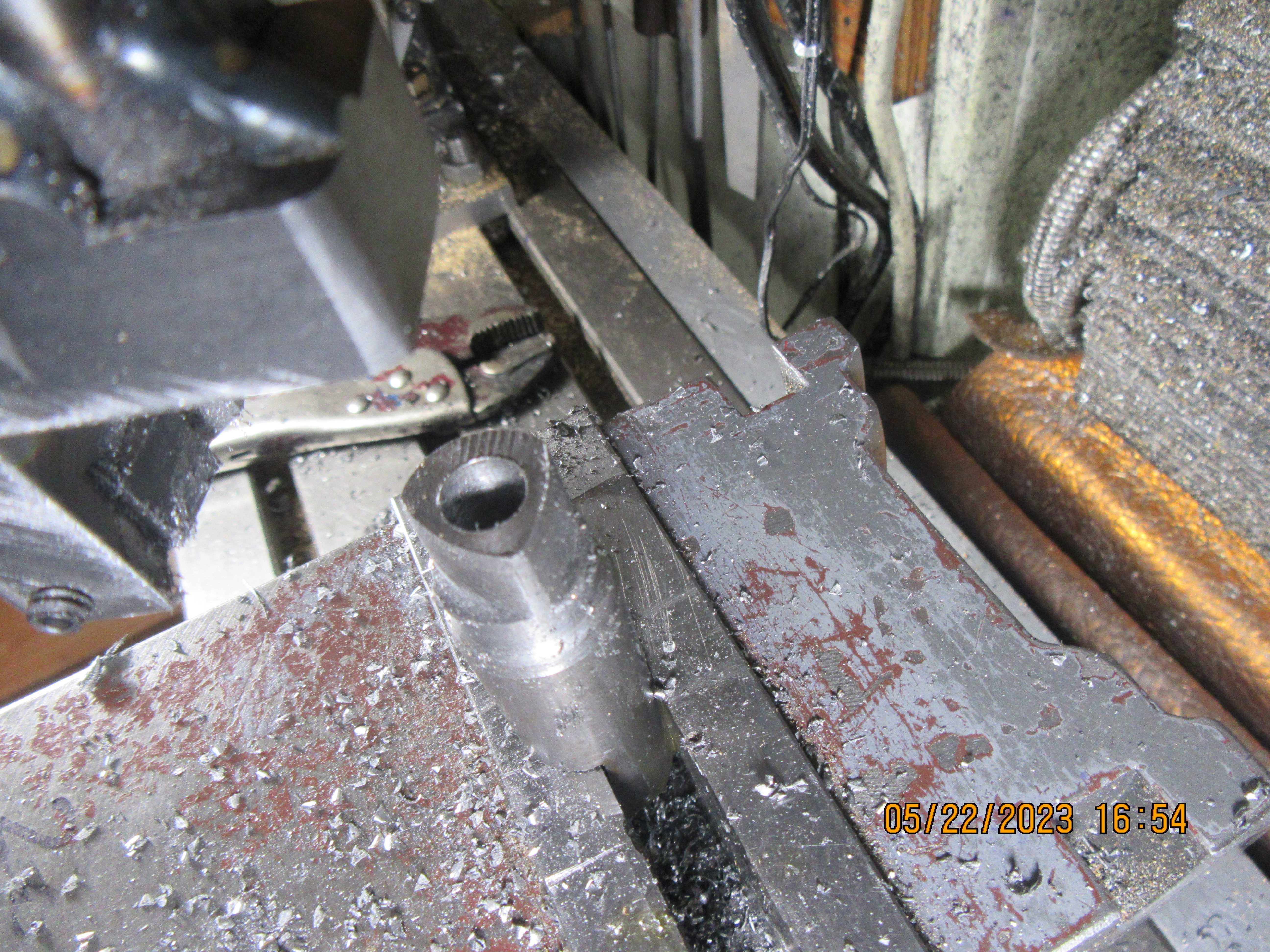
The second cut went very quickly. The mill table was offset from the spindle to the measurements on the cam drawing, 0.208 and 0.360" for cutting the first side of the cam. For the second cut I left the 0.208" offset with no change, but moved the 0.360 offset back to "0" and then kept on going until hit 0.360" in the opposite direction. this cut again took about five minutes. So far I am very impressed. The next set up will be in my rotary table to turn the last bit of material from the cam.
G3DNjO.jpg
 
The final machining of the cam went as follows.---Position the cam into the chuck on the rotary table with the highest part of the cam facing straight down and the angle readout on the rotary table setting on "0".
xImgMO.jpg
 
Turn the rotary table until it has rotated 180 degrees. Bring an endmill (larger in diameter than the cam width) down until it touches the high point of the cam and set your quill depth setting at "0". Now, there is a little simple math. If you split the cam vertically, there is 180 degrees of cam. Of that 180 degrees, 60 degrees has already been machined as the "radiused flank" of the cam and we don't want to machine it any more. That leaves 120 degrees of cam still to be machined on each side, so it's a total of 240 degrees split evenly around the center. Set your mill table position indicator at "0" and move the mill table in the x axis just enough to clear the endmill. Advance the endmill 0.020", then slowly move the table back into the "0" position--you will be machining metal when you do this. Turn the rotary table 120 degrees in one direction, then come back to "0" and turn it 120 degrees in the opposite direction. This cam has a difference of 0.080" between the highest point on the cam and the base radius, so repeat the above 3 times more at "0.020" advance each time until you have reached 0.080" vertical tool movement. That's it!! Move your part over to the lathe and polish it with 200 grit sandpaper strip.
DOF55D.jpg

jqZA7T.jpg
 
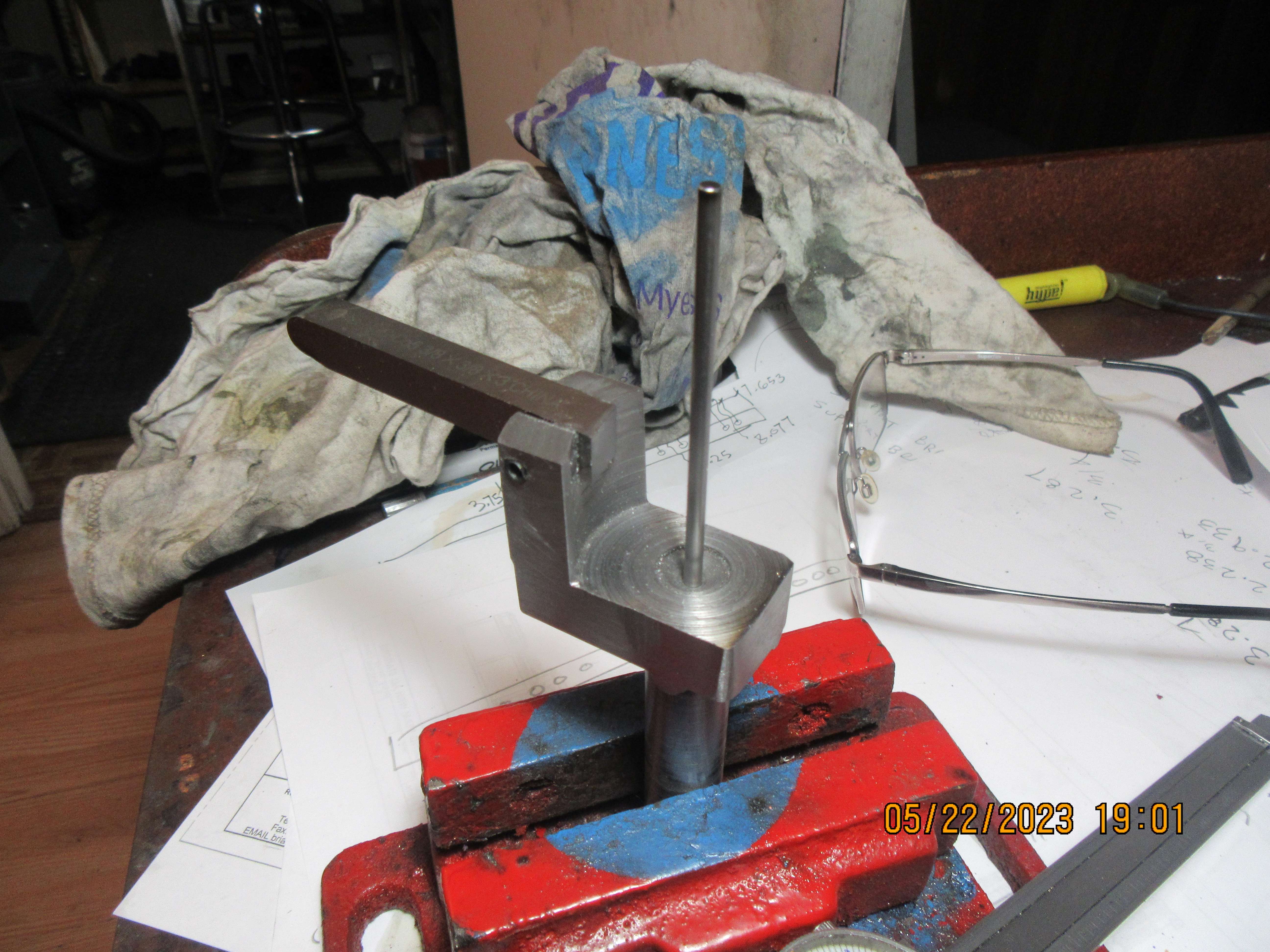
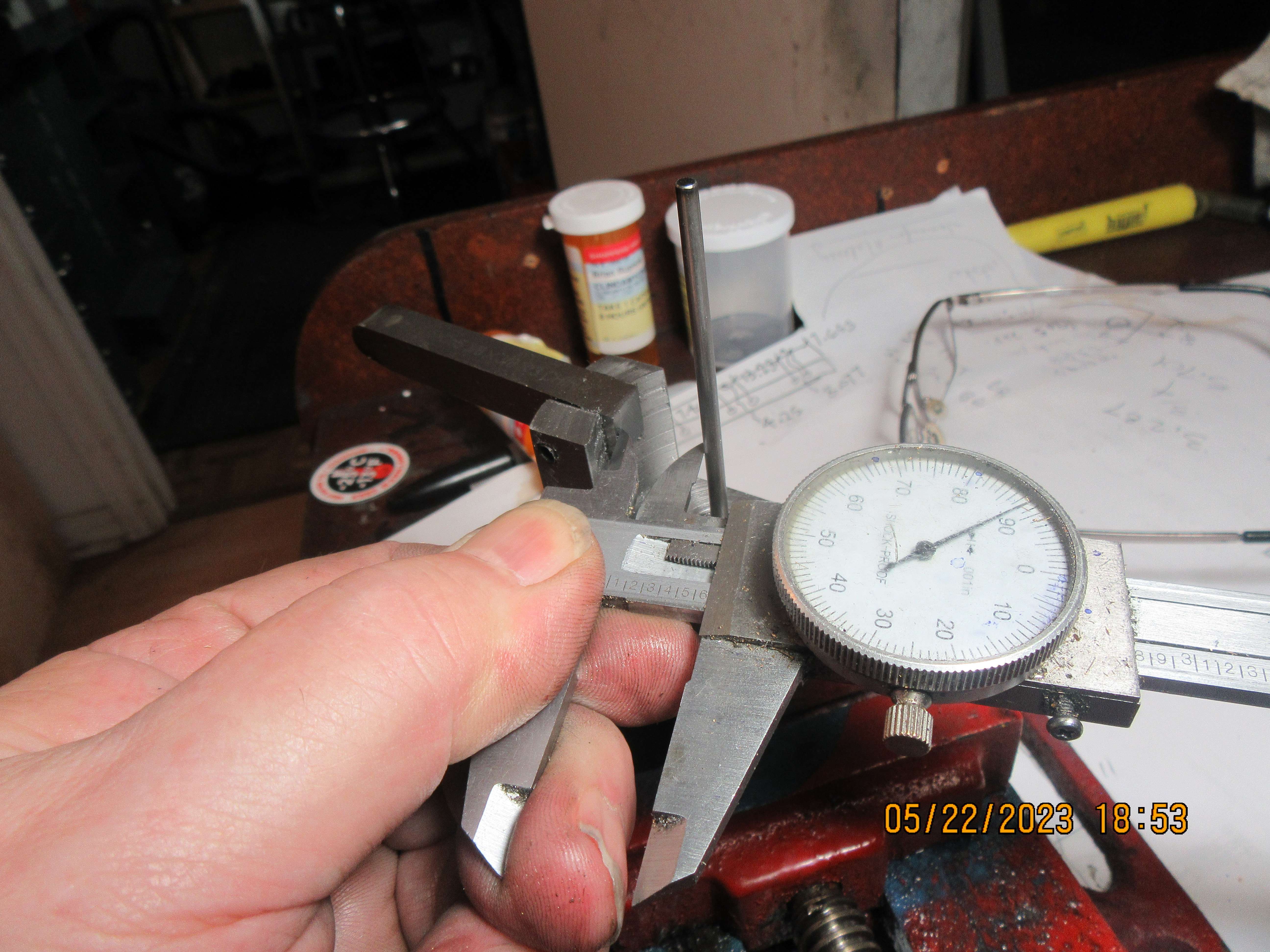
One final bit of magic---I couldn't figure out how to measure from the centerline of my new cam cutting tool to the tip of the cutting tool mounted in it. So---I drilled and reamed a 1/8" diameter hole x 3/4" deep in the business end of the tool and slid a piece of 1/8" diameter cold rolled rod into it, subtracted 0.063" from the desired dimension, then used my Vernier to measure the distance that I needed. (Don't pay any attention to the reading on my Vernier---this is a posed shot.)
tnNBOX.jpg

lQmB8W.jpg
 
It would be a lot easier to do the milling with the work stood vertically (table set horizontally) so you use the side of the cutter and rotate the table.
 
I'm happy that the new cam cutter worked. The cam I made is serviceable, and it's an exact match for the cam I used in my flathead (sidevalve) engine. I prefer my cams to be slightly larger, and as a comparison I have pulled up the cam that I used on my T-head engine. Vietti was right--this could have been done using a boring head with a left hand cutting tool in it. I don't have any left hand cutting tools for my boring head, and I kind of like having a dedicated tool that I can use to cut all of my cams. It wouldn't be used for anything else, and would be totally dedicated to cutting my cams and for nothing else. The larger cam as shown is suitable for a 3/8" diameter shaft, and can be bolted and pinned to the side of a gear.
 
Brian,

You don't need a left hand cutting tool. The tool is facing the center instead of the usual outward orientation. The mill is run in reverse to make the tool cut as it should.

Randall was a good friend and though he explained this method to me several times it just did not click so I continued to make cams by various other methods. Since I am building his Hoglet I thought I should use his method. It works great and is fast!. Since I'm making a two cam version of the engine I had some ideas of cam profiles I wanted to try out. I machined over 20 trial cams from al to see how to go and make cams of varying profile. I could make a cam in 5 min. Waiting to see how it works!
 
This morning I decided to make a dedicated tool to cut a slightly larger cam than I made yesterday. The cam I have chosen to be my "standard" is the same profile as the cam I used in my T head engine.
1nD3e8.jpg
 
Back
Top