I've been out sick for a month. Very bad back pain and arthritis. Yesterday, I felt like designing something for the first time in a month. I have no CNC in my shop, only manual machines. I know of two ways to make a cam with radiused flanks. Both ways are somewhat tedious, although they do yield a very nice cam. I may have came up with a third way to do this, so today I'm in my shop working on a prototype. If you don't know---a cam with a roller tappet works just fine with no radius on the flanks at all. But--A cam with no flank radius can't run properly with a normal round, flat bottomed tappet.--Every time the flat non radiused side of the cam hits the flat bottom of the tappet, it "slaps" it. This is bad ju-ju. Although some people get away with it, I prefer to do it the right way. My method requires a number of simple steps, and I will try to walk you thru it.
You are using an out of date browser. It may not display this or other websites correctly.
You should upgrade or use an alternative browser.
You should upgrade or use an alternative browser.
Cutting a cam with radiused flanks
- Thread starter Brian Rupnow
- Start date

Help Support Home Model Engine Machinist Forum:
This site may earn a commission from merchant affiliate
links, including eBay, Amazon, and others.
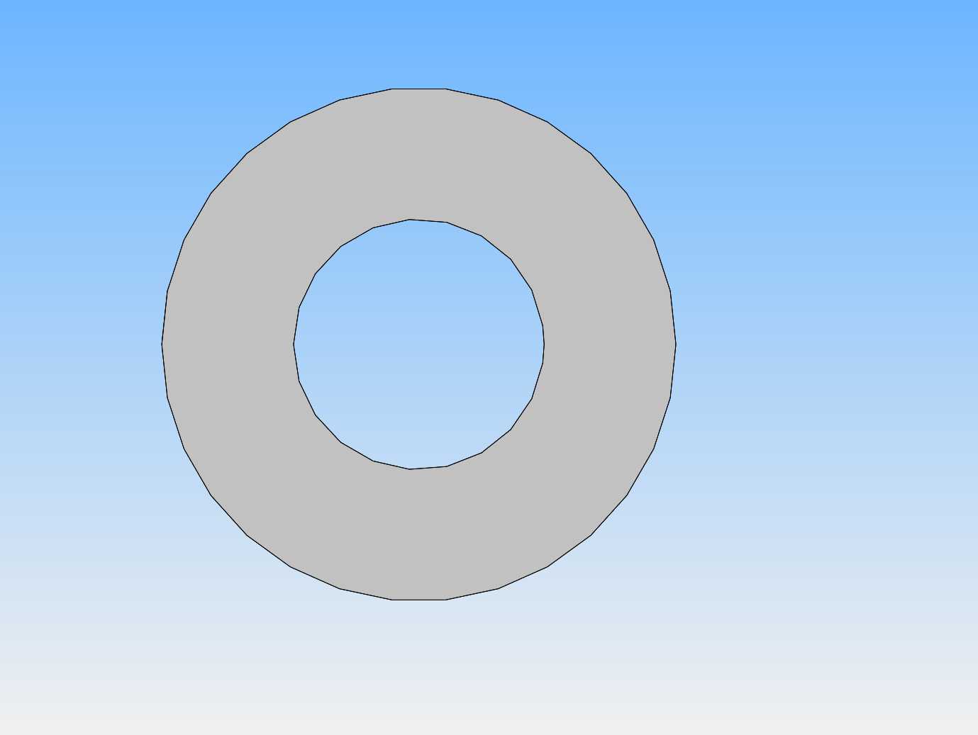
Shown here are the four stages of cutting a cam. In stage 1, the inner diameter is based on the final bore for the center hole and the outside is large enough in diameter to reach the maximum size of the cam after it is machined.

Last edited:
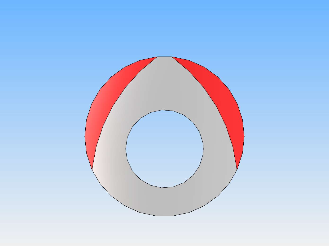
In step two (This is where we cut the radiused flanks) the cam is fixtured in a vice on the milling machine table, (remember, we haven't cut the cam to any particular thickness yet, so it is best turned onto a longer length of steel so it can be held vertically in a vice). My prototype cutter is dialed into the proper offset from the center of the cam, and as the milling machine turns it it is lowered over the cam to cut away one of the red flanks. Then after the first flank is machined away, the offset is again dialed in, and the prototype cutting tool is again lowered onto the cam to cut the other flank away. Notice that both flanks are not cut away in one set-up.

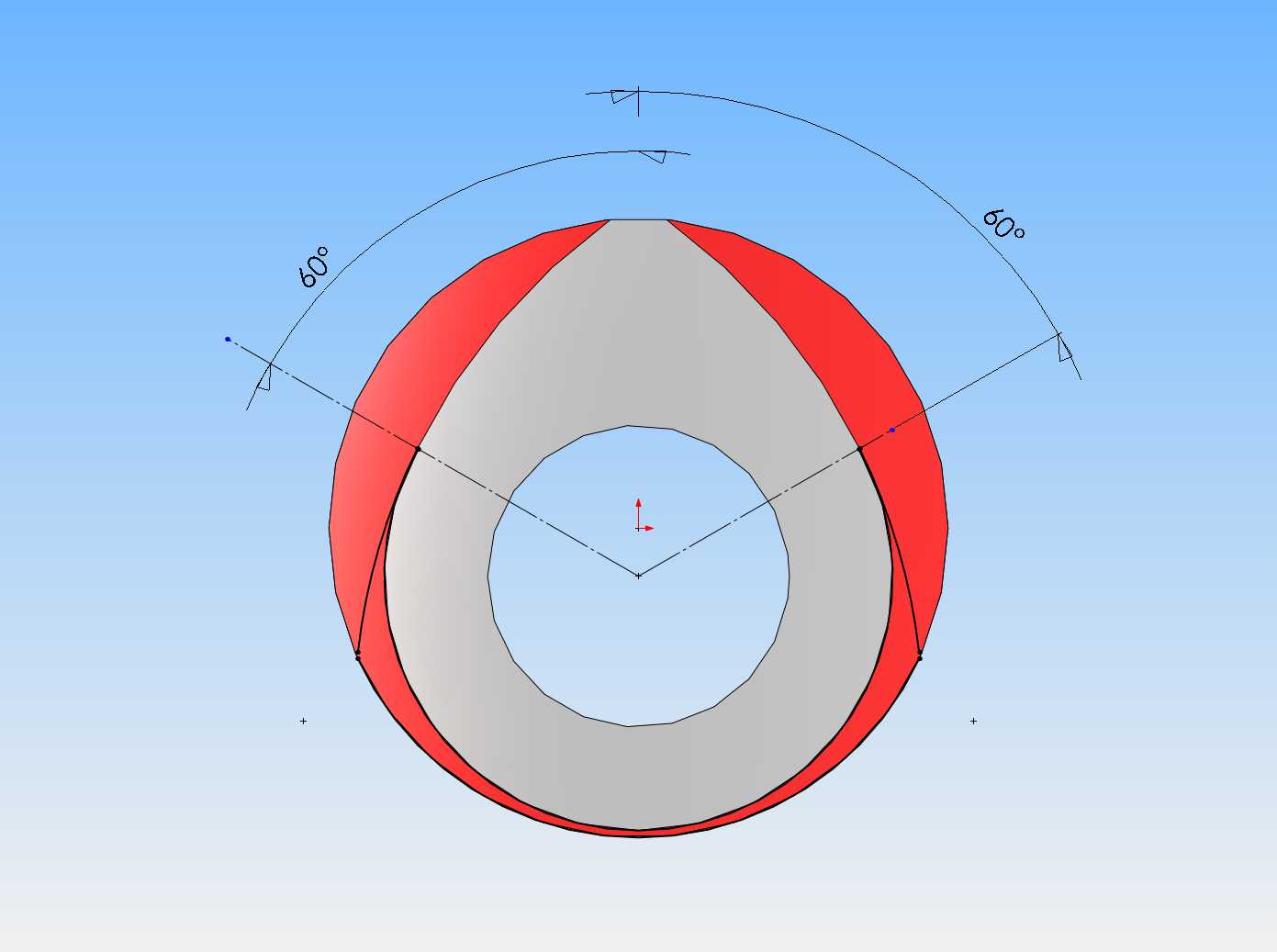
Okay, now that the curved flanks have been cut, we have to cut away the remaining metal at the bottom of the flanks. This will have to be done with the cam held horizontally in a rotary table mounted on the milling machine bed, and a 1/2" diameter endmill mounted in the chuck. I know how I will approach this step, but it is easier to take a picture "in process" than it is to explain it.

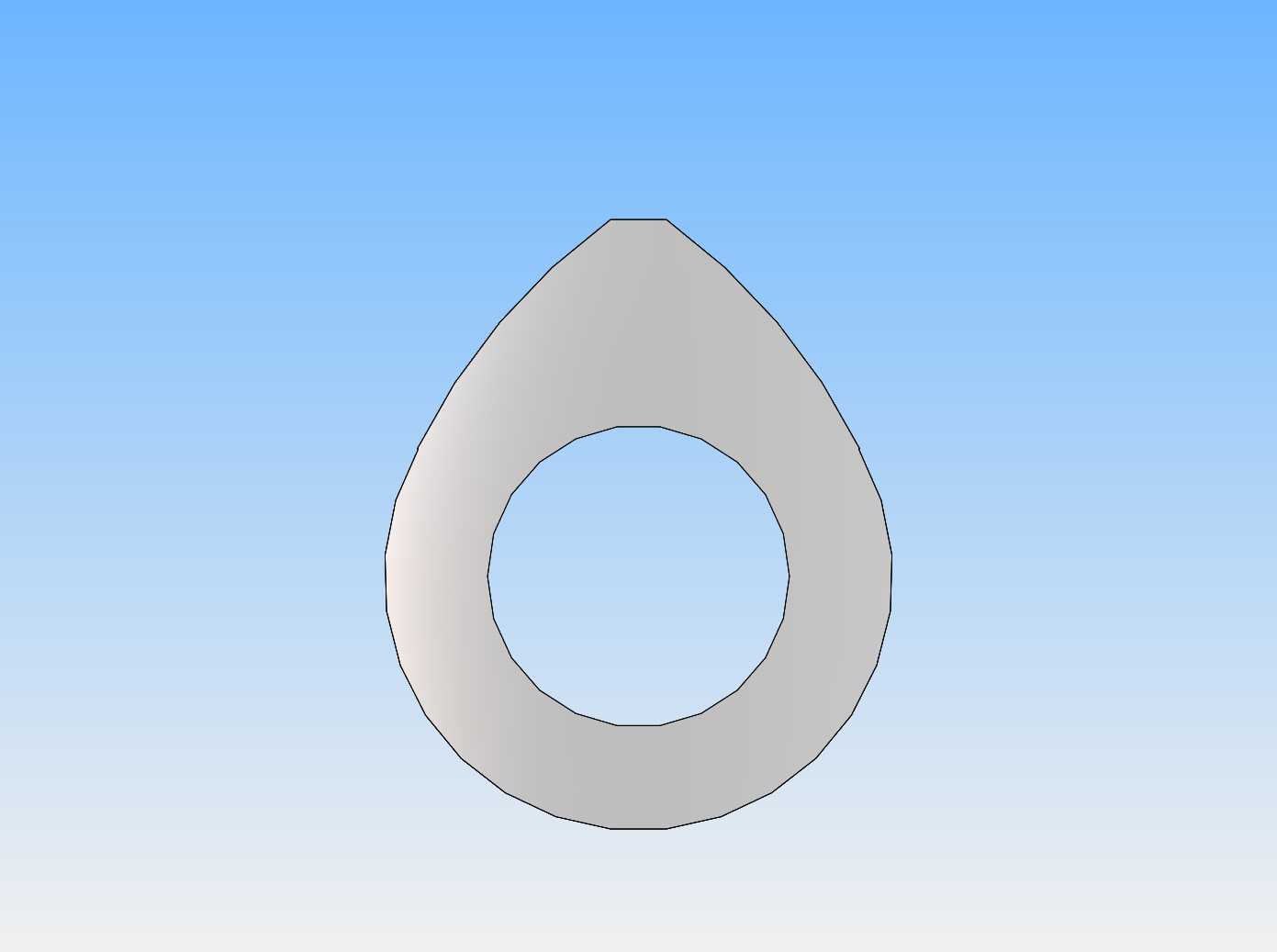
If we have lived right, this is what we end up with, a cam with curved flanks. Notice that there are sharp corners left at the top of the curved flanks. These corners will have to be rounded with a file to finish the cam.

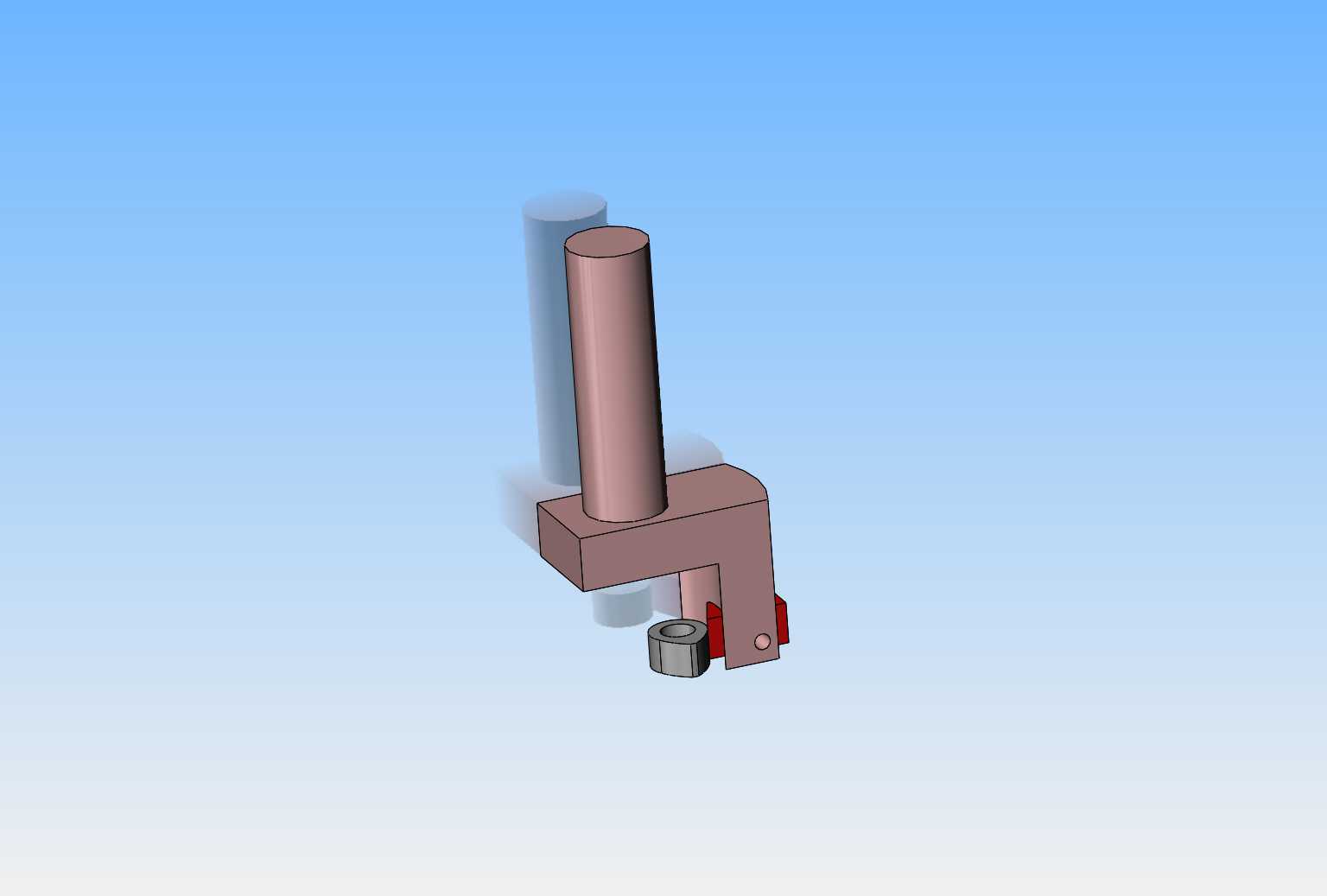
This is a 3D model of my prototype cam flank cutter that I designed. Note that I have also shown the cam in place. (the cam is held vertically in a vice for this operation).

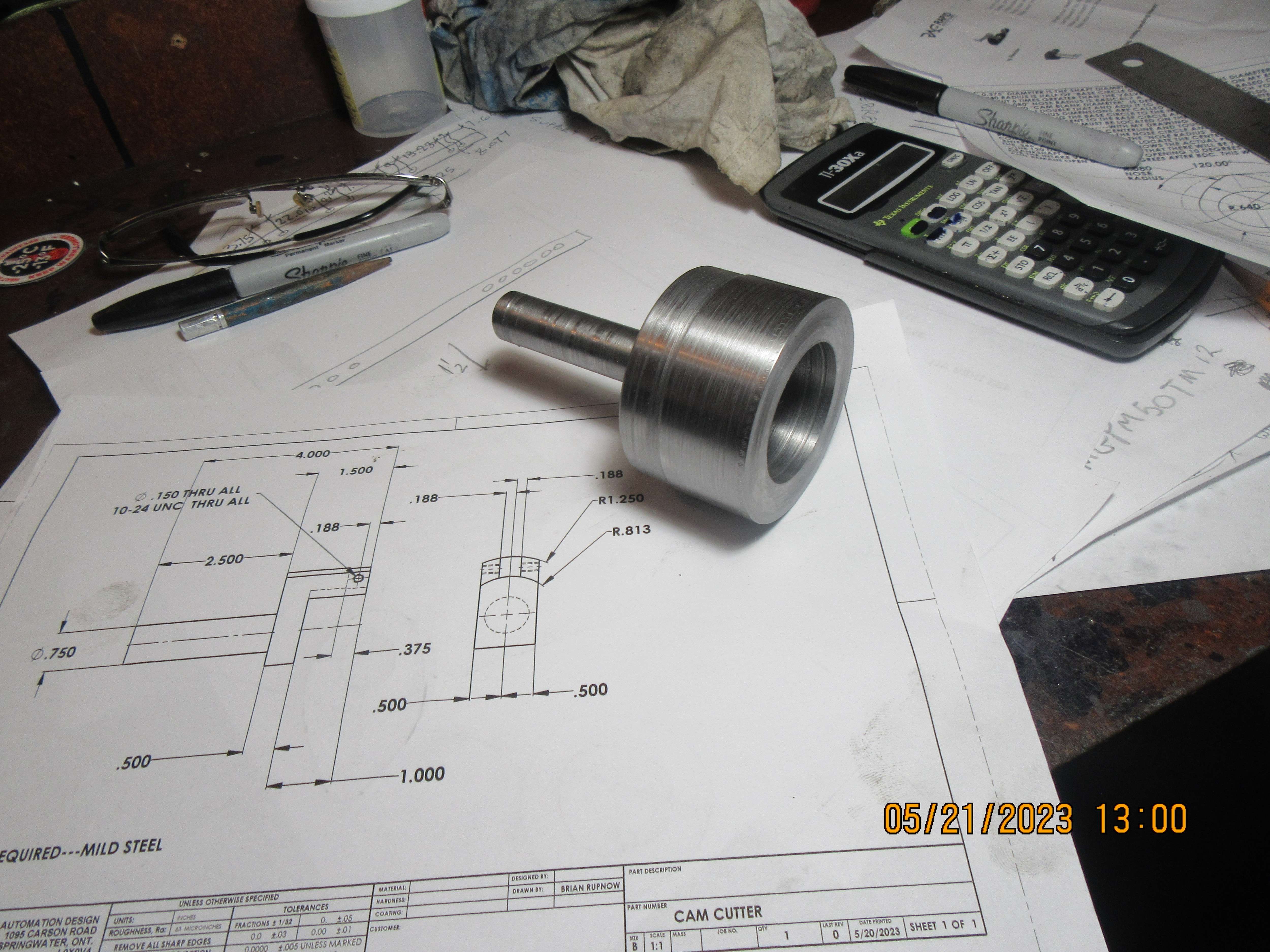
First, the main body of the prototype cutter is turned on a lathe. The design shows it made from one piece of steel, but I made it from two pieces welded together.

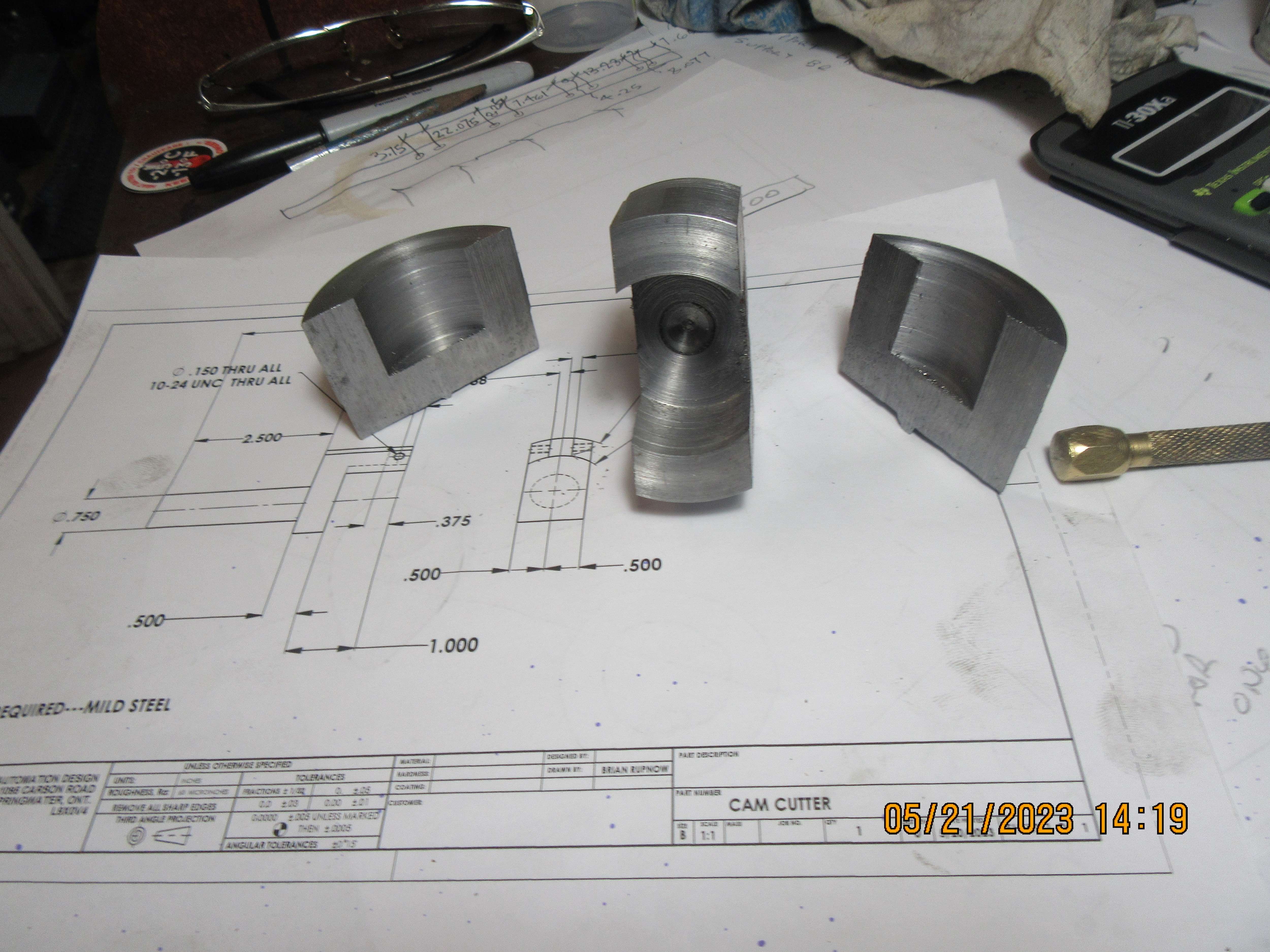
The next step requires a trip to my bandsaw, and the pieces I don't need are cut away, then the tool is cleaned up a bit on my belt sander.

The final step is one more cut on my bandsaw and milling the slot which the 3/8" square cutting tool sets in, and drilling and tapping two holes for #10-24 set screws. The cutting tool is about a mile longer than I actually need, but will work just fine that way.
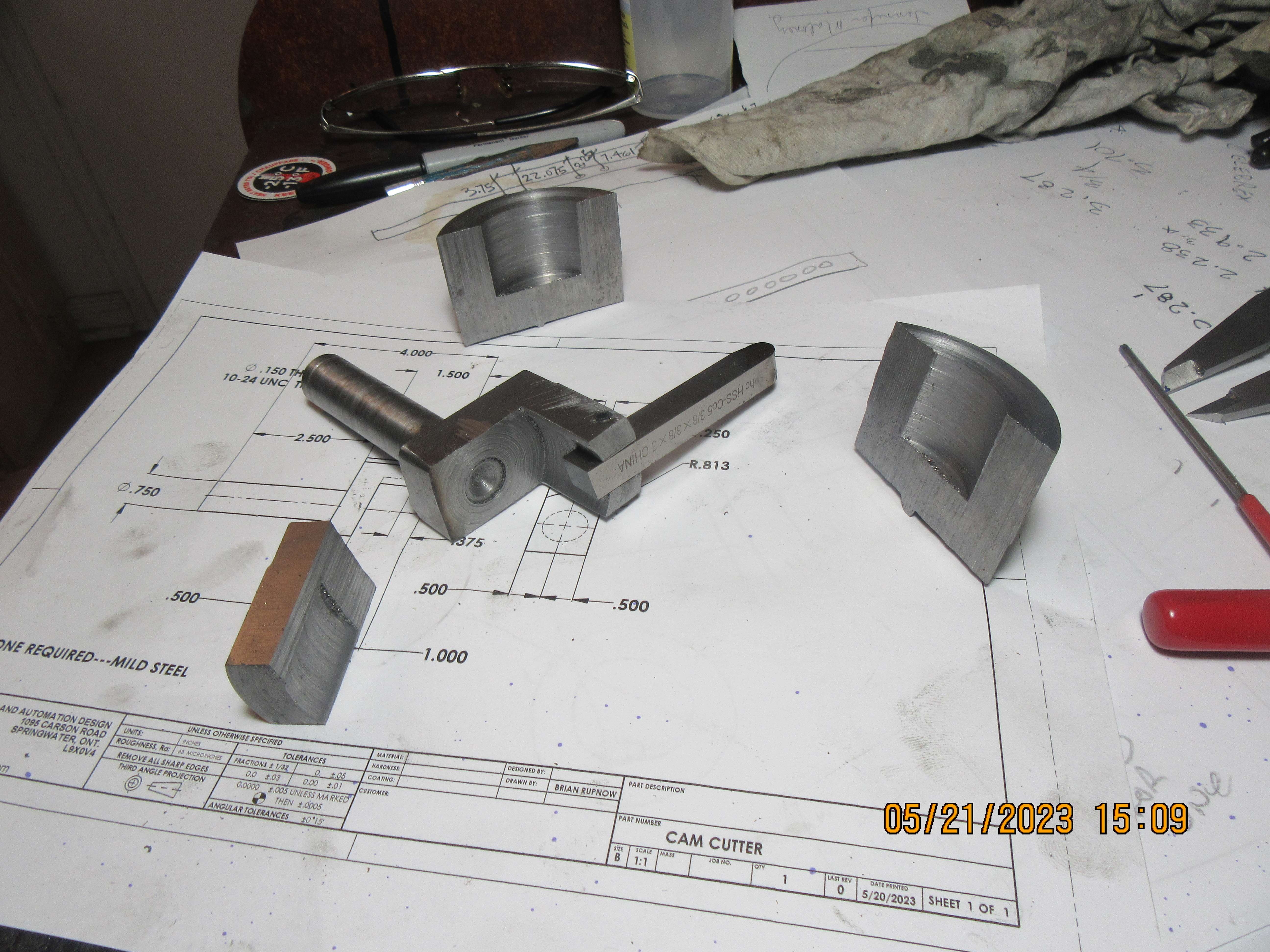

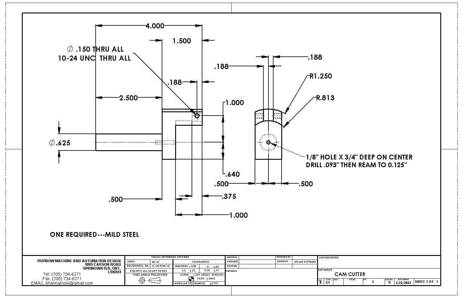
This is a detail drawing of the prototype cam cutter for cutting the radiused flanks.

Last edited:
You are well under way, but an alternative that may be of interest is the flank turning jig recommended by Edgar Westbury:
https://modelenginenews.org/projects/whippet/images/wp_cjig.jpg
shown in action at the start of this:
https://modelenginenews.org/projects/whippet/images/wp_cjig.jpg
shown in action at the start of this:
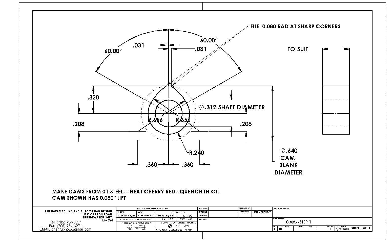
This is the cam which will be built. It is suitable for most medium rpm four cycle engines. The 5/16" bore can safely be opened up to 3/8".

Last edited:
Charles----I tried making a cam using a similar method to what you show, but found it impossible to hold the cam so it wouldn't rotate out of position while cutting it. Perhaps if I had made a jig like you show I would have had better luck.---Brian
Brian,
Interesting method. At it's heart is it different than the method Randall Cox described in building the Hoglet cams. I recently tried Randall's method and agree with his assertion it is a quick way to make a cam with a boring head in the mill turning backward and rotating an inward facing tool around the cam blank?
Interesting method. At it's heart is it different than the method Randall Cox described in building the Hoglet cams. I recently tried Randall's method and agree with his assertion it is a quick way to make a cam with a boring head in the mill turning backward and rotating an inward facing tool around the cam blank?
Vietti---Sounds like the same thing. Do you have a link to Randall Cox's article?--I'd like to see it.---Brian
Will look it up tomorrow.
Very nice Brian. Please don’t take this as criticism but, from a safety point of view, would it not be safer to clamp from only one side to hold the tool bit? Using two screws at 180 degrees apart could allow the tool bit to “Rock”, due to two opposing points of contact when tightened. Especially with the tool bit being much harder than the clamping screw, (no digging in of screw point to assist grip), also not helped if the cut is intermittent. Potential rocking of the bit could spoil the finish, but the biggest concern would be the possibility of the bit loosening and flying out at high speed at eye level! Again Brian, I’m not criticising, but as a fan of your work, I’m just thinking of your safety, take care!
Doug
Doug
This is howe Randall shows it, used here on my hoglet. No need to make fancy tools and easy to make fine adjustment of the radius


Looks like Randall and I had the same good idea. I will do a bit of research today and see if I can find a write up on Randall's method.
Similar threads
- Replies
- 43
- Views
- 12K
- Replies
- 7
- Views
- 2K


