Ceramic Gas burners on Locos

Home Model Engine Machinist Forum

Help Support Home Model Engine Machinist Forum:

This site may earn a commission from merchant affiliate links, including eBay, Amazon, and others.
It’s been a long time since I posted on this thread as I've moved to loco's that are coal fired However, I still get the occasional query and it seems that this thread has become bit of a reference so I'll post this here.

I got my jets from a model engineering supplier but recently I've purchased a 3D printer and sought a supply of extruder nozzles so turned to Aliexpress. They arrived today and my immediate thought was "these are gas jets". I hadn't noticed the similarity before. It’s understandable really, hobby 3D printing gained a foothold with RepRap and where else would they get nozzles?

Barely US$8 for 22 "jets" with shipping.

US $2.58 11% OFF|22 Pcs Nozzle MK8 Extruder Head 3D Printer for creality CR 10 CR10 Machine Heads 1.75mm|3D Printer Parts & Accessories| - AliExpress

View attachment 120401

Pete
Under where it says 22PCS it lists the sizes like 0.02 0.04 etc but they are not , they are 0.2 0.4 ( ten times bigger ) its stamped on each jet . Also the thread will almost certainly be 6mm where normal gas jets ( at least in England) are I believe 1BA
 
Hi Guys,
I have been making ceramic burners for 25 years or more, on and off. But the technology is limited by the laws of physics, so really a surface glowing the size of a firebox cannot provide enough heat to power the loco - if the firebox has been designed (sized) for coal. The coal fire, as well as providing the "red surface of coals" also gives huge amounts of hot gas - to transfer heat in flue tubes, PLUS the hot coals radiating sideways into the firebox lower walls ( a cold gas-air mix in a box for the ceramic). AND there is the soot... These soot particles, id incompletely burned in the fire box transmit with forced draught into flue tubes and continue to burn - and radiate heat - as well as provide extra heating to the gases - in the flue tubes. All in all as designed by George Stevenson, a jolly powerful heat source!
But the ceramic burner - if adjusted to a glowing surface - ONLY provides the radiant heat from that surface, as the gases are completely burned so the Carbon monoxide is consumed - which stops burning below 300deg. C -and the exhaust gas only has the small amount of residual heat from 300deg. C to steam temperature to impart as it passes up the flue tubes.
OVER fuelling ceramics - as explained by users - gives huge amounts of burning gas, but that is all, as the hot (not burning) exhaust in the flue tubes only has the residual heat of the gas (maybe 650deg C to steam temp) to impart. So you need a Lot of burning gas - and very fierce (fast combustion in the confined space of the firebox) to generate the heat and exhaust - that then needs the blower to drag it through the flues....
However: A solution is at hand, though only recent technology:
In steps:
  1. Ceramic: 950deg C max.: 120kW/sq.m.
  2. Stainless steel (wire wool) matrix: Metal fibre knitted matrix:1050deg.C. max.;200kW/sq.m
  3. High Temp. Stainless (ferro-chr. alloy)matrix (Sintered surface) 1050deg C max.; 250kW/sq. m.:
  4. Porous Ceramic burners: (Silicon Carbide porous matrix, or other modern clever materials):1450deg.C max.; 1000kW/sq.m.

Infraglow seem to sum it up in their on-line brochure: - worth a read:
https://infraglo.com/burner-types.phpGo-Gas have an interesting technical comparison table and clues about design.
https://www.gogas.com/en/process-heat/porous-burner-radimax
Also, search for "CREMADOR - Joan Lluch": as he has made a big and powerful firebox burner... - wire mesh type: - but he has a resonant noise problem to overcome.
Note: Regular stainless steel wire wool burns-up quickly: Special alloys are used by the Burner Manufacturers.
The porous matrix materials cost $100 per small block - so I haven't bought any to make myself a burner, but the 1000kW/sq.m capability is big enough to make firebox burners suitable for boilers designed for coal firing. (8 x more powerful than ceramic burners.).
Over to you guys!
K2
 
Just spotted this one:
https://www.msrgear.com/blog/radian...te-in-all-weather-performance-and-efficiency/Also,I understand - from various sources - that the preferred medium for a porous gas burner is CORDIERITE porous foams. The burner comprises an air inlet at the jet, venturi, mixer tube (as "normal") - then with the mixture entering a low-density (high porosity) matrix for cold gas mixing and heating the mixed gas, followed by a higher density (lower porosity) matrix where combustion takes place: Combustion is COMPLETED in the matrix: NO extra air is required for post combustion. But the whole of the high density matrix glows brightly at 1400deg.C. (ish) with the internal combustion taking place inside the material. - like 1 big hot coal! The exhaust is supposed to be very clean. - So loco drivers will not get headaches from the CO normally blasted up the funnel in great quantities.
Bring it on?
K2
 
A big advantage with a radiant burner. The velocity through the flue is slower giving a greater dwell time to absorb the heat
I have recently built a simple marine centre flue boiler and comparing it to a water tubed flue of the same size the flue with no tubes heats the water faster and the outlet temp is nearly 80c lower .Also the temp along the length of the flue is reasonably constant at 510c to 620c
Its very 16mm loco in form and for my toy boats no idea how it would scale up
Often wonder if in larger loco fittings doing away with the blast system would make a more efficient set up
Another benefit is the amount of gas used drops by about 1/3 reducing freezing and cooling of the gas tank.Using just butane with an ambient temp of 6c the plant will still run a 1/2 by 1/2 double acting wobbler at 300rpm
radiant material canbe bought from the jewellery suppliers like Cousins
For mesh you really need to consider nichrome mesh as it last far longer than stainless but I tend to get around 12 or so burns from stainless. The likes of Wilko in the UK sell frying pan cover for a couple of quid and the wire just happens to be the right size to make number 3 jets double bonus for the penny watchers like me
cheers
 
Good stuff! But I wonder if there is really much heat flow from the gas to the boiler in the flue tubes? - The temperature should drop from around the 600 degrees (post combustion) to nearer 200 degrees (beyond boiler) if the heat is being "sucked" from the gas into the boiler. I would be tempted to put a wire coil inside the flue, not touching the side walls, to gain heat and radiate it into the side walls of the flue. (Black infra-red can't be seen but is still very effective). Also install some very loose stainless steel wire wool inside the wire coil. - The hottest gas will be in the middle. The coolest gas at the surface of the flue tube. You should heat the "wire wool" (or other) in the hottest gas so the heat can radiate across to the walls of the flue. That should increase efficiency of the heat flow into the boiler....

I have made Ceramic (and other) burners ranging from a no. 3 jet (0.2mm) (for Mamod boilers) to a 0.49 jet: - which was for Propane on a ceramic for a 9" dia boiler - 2 ft. tall. - That one was "short" of a lot of flue tubes, so needed the ceramic to create most heat suitable for heating the bottom of the vertical boiler, rather than the (Stevensons) loco multi-tube boiler that maximises the heat flow in flue tubes. I did some very crude calculations and decided the 9" dia boiler had very little flue CSA to take a 7kW or so simple gas burner. So I made a rectangular burner about 7" x 5" powered by 15psi Propane. - Rated at around 4.4kW. (see "International Toy and Model Steam Hospital" for the boiler). I've not seen many ceramics on models this big.
By comparison, a friend has researched the "heat" required for his 4" vertical boiler to drive his Clayton Wagon: 27kW: So it explains easily why radiant ceramics just don't have the rating to achieve the power density required for Coal-fired loco fireboxes! a 4" circle of radiant ceramic is only a single kW or so! - Good for making Tea....
However, as used in domestic central heating boilers, a 5" x 3" plaque can be used (non-radiant mode) as a surface diffuser for 25kW or so of gas flames in the water-tube boiler. - I understand successful 5" locomotives usually have around 30kW (or more?) of gas combustion in the firebox - using some very fierce multi-nozzle blow-lamps. (look-up J.E.Nystrom).
K2
 

Attachments

  • P4182448.JPG
    P4182448.JPG
    274.3 KB
All good stuff and very interesting
The idea for the small plain flue is to keep gas velocity low allowing more dwell time. It seems to work from the rough ars££ experiments I can conduct
Using different burner ideas the flue exhaust has dropped about 140c and the gas consumption has also gone down. The engines rpms have gone up to near what I need for this wee boat. May have to take it to Roker for a test run when she is finished although a Stirling engine based on the Glasgow engine is on the bench.
Nothing new the loco guys have used the idea for sometime in the small scale stuff
The Clayton is greedy for steam or at least my engine is. Although she has not been steamed for over 20 years and needs a full rebuild. Maybe someday it will happen.
I only build the smaller stuff now just cannot afford the big toys and no longer wish to be in a model engineering club
keep well
 
Gentlemen:
I have been fascinated by these series of posts. I spent a good deal of my career doing combustion/ steam calculations. So I will comment. If you know the required steam flow per unit of time you can calculate the heat input. The flue gas heat loss is significant due to the water of combustion. So when you calculate the heat required for steam generation you must divide by that efficiency to get fuel actually fired. Its very difficult to get efficiencies above 85% unless there is a condensing heat exchanger involved in the unit. Only in modern furnaces are you likely to find that. Dividing the calculated steam heat requirement by the efficiency gives the minimum burner size for the system. After that its a matter of how well the boiler is designed to capture the heat, and how much excess air you are using in the combustion chamber.
 
Tell us more... I use "Model boilers and boilermaking" for a basis of my calculations, along with some theoretical gas consumption tables per jet size, and a huge fudge factor (<70% of expectations become reality). The biggest difficulty I find is in estimating heat losses... so I really go to town with complex insulation on my boilers. (Just a sheet of "bought insulation" is laughable to me!). I feel boiler and pipework losses are the most neglected areas of model engineering.
Any advice is welcome!
I am also a believer (as an ex-design-engineer) in calculations predicting optimistic results in the hands of the inexperienced. I spent some of my life being inexperienced in most things! (Now I reckon I'm inexperienced at everything).
Ta, K2
 
K.N.Harris advocates the only air in the fire-box should be primary air, as any un-used secondary air will reduce efficiency of the boiler. Many (especially people converting coal-fired boilers to gas) want lots of excess secondary air... ceramic burners lend themselves to zero secondary air when we'll designed and in a suitable boiler. But (Imho) boilers designed for coal firing seldom offer optimum heat transfer for gas firing. Not being a chemist, I can't calculate the volume of gas passing through flues for gas and coal fires of the same thermal output, but I guess the coal fire produces denser gas with all the carbon dioxide produced...so can get "more power" from the same flue CSA. Alternatively, gas needs bigger flues for the same power as a coal fire. - Is that correct?
K2
 
A most interesting thread. I had come to conclude that gas burners as applied to model steam locomotives were something of a black art, even given that there's a gentleman in Finland who has used 'in flue' burners, which I realise aren't necessarily the subject of this thread. I have two 'gas specific' boilers in 4mm copper, flanged and almost ready to silver-braze. Both have 38mmx3mm copper tube flues. There are two flues in one boiler, three in the larger. The larger boiler is about 180mm diameter. I have fiddled for ages with all sorts of burner lashups and I feel the stainless steel mesh, as a sort of 'glow cone' in the flue works, but is perhaps not the way to go. Interesting, though is the idea for nichrome mesh, but just where does one get that? Nichrome wire I do have, but mesh?
I've made many and varied gas jets for all sorts of positions and I've become fairly adept at drilling 0.4mm holes in brass jets. But 0.4mm doesn't seem to be small enough. Then there are jets available for 3D printers which look promising, but I doubt they'd be small enough, either. The ceramic burners, in conventional fireboxes being discussed, seem not to be able to supply heat in the flues and that was another part of my reasoning for the 'gas specific' (or 'in flue' burners) design. The Finnish gentleman suggests as few flue tubes as possible, as does Kozo Hiraoka in his Pennsy switchers, both of which are coal fired. What I'd like to find is a design for 'in flue' burners. I'm weary of the empirical methods. I have more than few failed experiments! There are a few designs for poker burners on the 'net. Ron Reil's come to mind.
I live in Australia and even given our abundant supplies of coal, it's difficult to source good steaming coal. Some clubs do actually import Welsh coal. We once had a supplier of 'char' who has since ceased trading, therein lies yet another part of my reasoning for gas specific boilers. These boilers are very much simpler, particularly in flanging and staying. I use the Australian Miniature Boiler Safety Committee's methods for calculations and I find the AMBSC specs. to be indispensable.
 
Hi Wazrus. My experience. In the UK there are model suppers (e&@y) that will sell jets 0.15mm and 0.2 mm and above for £2.50 inc. P n p. But I buy cheap Chinese drills for 0.25 mm and above and drill my own jets. Not perfect, but I buy 10 drills for the price of 1 jet, so I' m on a winner at 2 or more jets per set of drills.
But I wonder at the power you need for that decent sized boiler at 180mm diameter. Jets basically limit the gas that you can have. So look-up some tables for the BTU per jet size, convert to kW, and assume you need over 30 kW of burning gas to power a loco big enough for your boiler, and I guess you'll need 2 or 3 burners at 0.4mm jet! So why do you want smaller jets?
I also think for you dia 35mm fire tubes you need blowlamp type burners, with cones of radiant material. What may work for you is a few coils of nichrome wire. Say that you have 0.5mm wire. Make coils at 10mm, 14mm, 18mm, 22mm and 26mm, and with some wire spacers fit them inside each other, and use a propane blowlamp into the flue tube with the coils, and see if you get a good glow for a long length. The dire is the have visible red heat for 2/3rd of the flue tube length, but use the coils full length as even the black heat from wires will pump lots of radiant heat from the gas exhaust into the flue metal walls. Check exhaust temp of the exhaust from the flues, then you can compare wire heat exchanger configurations. Remember. Gas below 350deg.C. will stop burning, so if the gas temperature is over 350 just after the last flicker of flame, then you have burnt all the gas. Otherwise you'll be creating a Carbon Monoxide exhaust. That is dangerous, so please experiment outdoors, or have a CO detector (and believe it!) If indoors.
For those that don't know. CO in any amount causes permanent brain damage. In your life, the more CO you inhale the quicker you'll bring on dementia, so avoid breathing it wherever possible. End of safety message.
The alternate way to have a gas burner is to have a very large surface area of radiant: e.g. a large flat ceramic or wire mesh radiant burner the whole length of the underside of a long horizontal boiler, with all the gases directed to one end and through longitudinal flue tubes. My stationary boiler is this configuration, but most locos would not suit this (conventional designs that is!).
Cheers.
K2
 
For those that don't know. CO in any amount causes permanent brain damage. In your life, the more CO you inhale the quicker you'll bring on dementia, so avoid breathing it wherever possible. End of safety message.

This is overstating the risk and being alarmist in my opinion. Obviously too high a concentration is very dangerous but there is a threshold where damage starts to occur and we are all routinely exposed to at least some CO as a product of almost all combustion processes (including the humble log fire). To suggest that minute amounts of CO exposure contribute to dementia is completely unfounded in literature. Even brain injury organisations do not make such claims : LINK.
 
Sorry Cogsy,
Seems I have the wrong answer again..., I just remember what my school chemistry teacher told us about smoking. The CO combines with haemoglobin to form Carboxy-haemoglobin, which in turn blocks oxygen transmission to the brain - causing headaches, permanent brain damage, and potentially death... But I have no idea what concentrations we normally live with - having grown-up with coal fires, dirty vehicle exhausts, paraffin heaters in the front room, smokers everywhere until less than 20 years ago, and the teachers (most of whom smoked) said there was enough CO in a cigarette to cause "some" damage...
When I have a major blow-lamp job that sets-off the CO alarm in my garage, (Rarely!) I do the sensible thing and get out and ventilate the garage. - Because I don't know any better... But my model boilers (burners) don't set-off the CO alarm.
And I was told that my Mother's dementure in Old age was caused in part by a lack of oxygen to the brain, that occurs as the body ages. But I haven't studied dementure, just know it isn't good.
I'll have a beer and crawl back into my corner... - or does the alcohol affect the brain?
Cheers mate!
K2
 
No need to drill 0.2mm holes for jets ,Simply drill to 0.4 and swage the hole down around a correct sized bit of wire. My lathe wont go fast enough to drill .2mm . The loco guys have used the idea for years
I tend to make 10 blanks drilled at 0.4 then swage them to the size I need
On my simple marine boilers I find the burner csa should be no more than 1/3 of the flue area. They must be only fed by primary air or at least the ones I make?
The nichrome mesh is available on ebay and is sold for something to do with those ecig thingy ma bobs.
I do use steam tables and start any boat build with a scale speed in mind and start with the prop this gives rpm this gives steam consumption and so on
with a good bit added for losses
A wee video of an experimental Cracker

And a wee plant for a 10 inch Puffer


Just built for the fun of it
A pic of the simple marine boiler
keep well
cheers
 

Attachments

  • PIC_0028.JPG
    PIC_0028.JPG
    332.3 KB
Last edited:
Tell us more... I use "Model boilers and boilermaking" for a basis of my calculations, along with some theoretical gas consumption tables per jet size, and a huge fudge factor (<70% of expectations become reality). The biggest difficulty I find is in estimating heat losses... so I really go to town with complex insulation on my boilers. (Just a sheet of "bought insulation" is laughable to me!). I feel boiler and pipework losses are the most neglected areas of model engineering.
Any advice is welcome!
I am also a believer (as an ex-design-engineer) in calculations predicting optimistic results in the hands of the inexperienced. I spent some of my life being inexperienced in most things! (Now I reckon I'm inexperienced at everything).
Ta, K2
Will start with the burner size. Boilers design is part art and part science. So to start off with will go with a small boiler that needs to have its fuel input evaluated so we can estimate the burner size. We want to know in calories or btus how many are needed. At this point it does not matter what the losses are we want the theoretical heat input. Forgive me but I will use the btu system. Its the same method for the metric system.

Lets say this model boiler has a steam output of one lb per hour and its operating pressure is 5 psig or about 20 psia (absolute). From the steam tables found in textbooks or now on line we determine that this lb of steam has 1157 btus per lb of energy. Now technically I should give credit of the energy of the incoming water and it will range between 18 and 150 btu per lb depending on the water temperature. but to make my life easier for this simple example I will ignore it. Now we know from various calculations of combustion that the water of combustion will comprise a major heat loss up the stack.
A good coal will be about 85% whereas gas might be in the range of 78%. So because I know nothing is perfect I choose a number of 75%. I take my 1157 and divide by .75
That means I have to deliver 1542 btus in fuel whether I burn coal, gas , or oil. For grins I want coal and it has a heat value of 10000 btu per lb. And for one hour of operation I will need about .15 lb of coal for my steam engine to operate for one hour. A gas burner would be a little trickier because we have to consider burner size operating pressure, but it can be done. Ceramic heaters would also have to put out 1542 Btus in an hour.

But this is an area I do not know very well. I would think that a ceramic heater would not be capable of as much thermal radiation heat transfer. A furnace is designed to absorb this heat with the rest being absorbed in the back passes of the boiler. The flue tubes absorb heat by convection heat transfer. You want these to be as clean as possible with an acceptable pressure drop.

So I hope I haven't taken the fun out of making a model steam boiler. But I will tell you even the big boilers face issues in the design and start up. And we only just covered the numbers for fuel input.
 
I got a PM from Tups (Cris) for more details on the replacement ceramic burner I have made. This one works and if I dont forget to open the blower before I stop running it doesnt go out.

Some of this is a repeat from the Rob Roy thread but for completeness Ill do it again here and hopefully by the end it will all make a bit of sense;

The problem I had been having with running my loco successfully on gas was although I could get the engine up to pressure relatively easily maintaining it was a problem so I ended up going round the track in short runs followed by a recovery of pressure then on again. On the assumption that the more heat you can get into the engine the more steam you make and keep up the pressure. I have been experimenting with burners and learned something from the exercise. Some of it is blindingly obvious but it has helped me understand what is going on, or not as the case may be.

The basics being.
· To get more heat you need to burn more gas (I said it was blindingly obvious stuff)
· The amount of gas you burn is a factor of jet size and jet inlet pressure.
· You need the right balance of primary and secondary air to ensure complete combustion (its about a ratio 1:24 gas:air for propane (4%:96%)
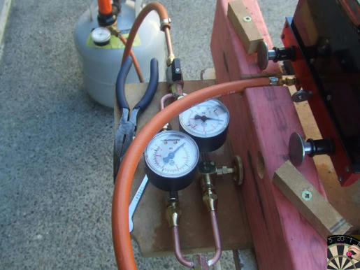
I made myself a test rig so I could see what was going on. Regulator on the gas bottle, Input pressure gauge and output pressure gauge after the gas tap

Gas Control Rig

8t5o7y5ppvaxu3o4g.jpg


The assumed problem with the ceramic burner was that it couldnt get enough secondary air. If it is running on the electric blower its fine, on the steam blower its fine. But add more gas and the engine whistles like kettle as it tries to draw air through the holes on the firebox door. If the pressure is too high, and the blower is off, it flashes back with a huge pop or just goes out. If it goes out there's no indication as you can still hear the gas flowing. Not good

My starting pint was the local guys who had given me a lot of advice based on the success they had with gas firing their locos.

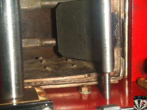
First was to put a baffle on the front of the burner to keep the flames in the firebox for a while rather than shoot straight down the fire tubes. This keeps the heat where you need it and stops you melting the paint on the smokebox. Believe me it works, I ran the loco once with it out and the smokebox paint job looks a bit sad now.

Stainless Baffle on original burner

jzc2tl5ytz1mynl4g.jpg


Baffle in the firebox, note its at the fire tube end not the fire door end.

587t2xfaymjokjl4g.jpg


(I am convinced this is a major contributor to success)


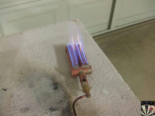
The next was make a new burner I started with making a new burner based on some old magazine articles, the intention being that the gaps between the tubes would allow enough secondary air.

3p3s1nwik92dzdd4g.jpg


This didnt work too well and made a couple of versions but they just didnt give the heat and there was lots of un-burnt gas.

New Burner

I then turned to resolving the secondary air issue with the ceramic burner I had seen a version of a burner with tubes running through it. I wasn't about to hack my burner about in case I was wrong so set about making a copy

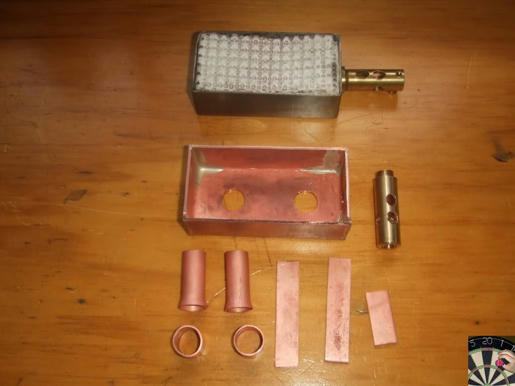
All the parts alongside the original

a4690xaxxnvupx94g.jpg


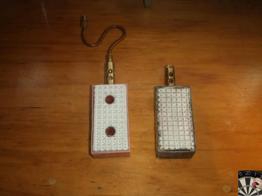
New and old

kury79arihr3qhc4g.jpg


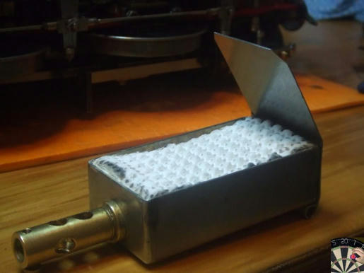
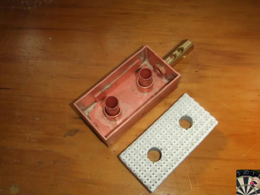
New burner with the lid off

zwxl101c4jxd8g84g.jpg


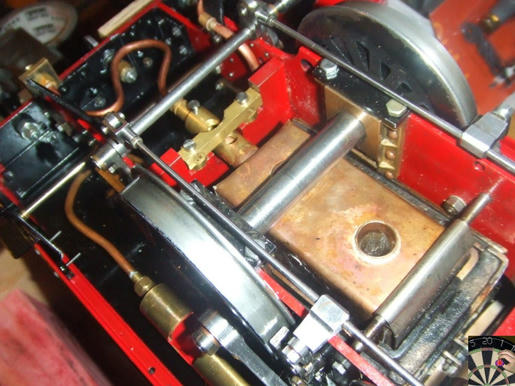
Installed in the loco you can see the baffle in the front

jsfaapn1nddl7lk4g.jpg


Make sure that the burner is as high up in the firebox as the jet holder will allow e.g hard against the foundation ring.

The dimensions for mine is 26mm high, 42mm wide 85mm long. This just fits in the firebox allowing for the ends of the stays and a little bit of room for the baffle

Through the middle are 2 x 12mm tubes for the necessary secondary air . To hold up the ceramic there are 2 x 15mm sleeves around the air tubes and strips of copper soldered on the inside edges of the body.

The jet holder is 38mm long 12mm dia brass drilled 8mm for the jet assembly, It is cross drilled with 6 x 5.6mm holes set at about 60degrees. The jet is a #15 held in with 6BA screw. The jet holder is mounted as low as it can be in the burner body. I'm sure it can be longer, as your installation would require.

My original was stainless steel, this one is copper, as thats what I had. Im sure brass would be just fine. (either way16-20swg)

I got my ceramic from Bruce Engineering (Polymodel) in the UK

Polly Model Engineering: Bruce Engineering, Model Engineer's Supplies

It cuts really easily; I did the holes for secondary air pipes by using an offcut and twisting it slowly as it worked through the material.

See these drawings from Sandy C his burner gives a good view of a similar sort of burner albeit smaller and no secondary air holes. However it give you a good idea on sizes. Most of my burners have had some basis on this burner from Sandy and there does seem to be some commonality with parts.

Home Model Engine Machinist Forum

Running with it

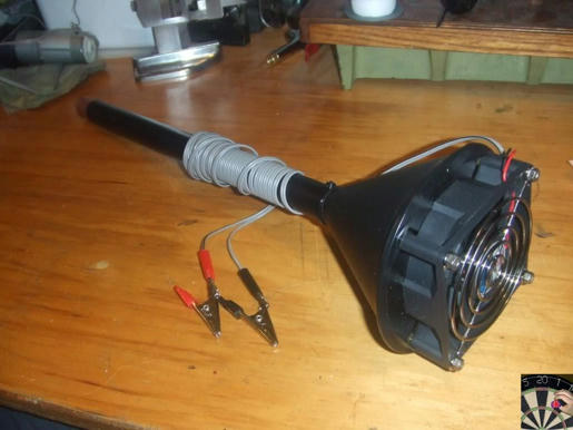
As with any loco a blower is needed to get the burner running otherwise youll get lots of flame out of the firebox door. I start at about 5-7psi gas pressure with the blower going, it doesnt need much of a blower, I use a computer fan in a cut down plastic funnel on a long coper tube so the whole lot doesn't melt. That said with the baffle it not like there's flames shooting out of the loco flue.

dxbpq36eqc3c7a44g.jpg


Once a bit of steam pressure is available (5-10psi) the steam blower can be opened and the external fan removed. As steam pressure comes up more gas can be applied. I find that 20psi max is good for my burner on this loco. It takes only about 10 mins from cold to full steam pressure (80psi), my boiler takes about 500ml of water.

OK I understand theres a but of reluctance to go to gas burners, but when they work they work pretty well, and clean up at the end of the day is just about zero in the firebox area. And if you have a problem with water, as I have been having on my small loco, no grappling for the dump pin. Just shut down, sort the water, if you've got steam pressure and bit of steam blower and re-light.

Hope that is of use to somebody

Pete

PS

For those of you who missed it, here it is running

[ame]

Dodgy track at the end caused it to slow and stop

Unfortunately, since 2011 Sandy C Appears to have dissapeared...?
So the link to his burner design does not work for me.
One point I note is that the air supply through the burner is too small for the jet. Using a #15mm jet (~0.34mm dia. ??) you should have at least a 12mm hole up the mixer tube (for Butane at 15psi: Propane at 20psi) otherwise you can't get enough air into the burner body for the flames to burn properly on the ceramic. - You may be able to get away with a 10mm dia properly designed venturi, as gas n' air flow is super-complex.... (literally "Aircraft" and "rocket" science!!). Hence all the secondary air and forced draught needed with this burner with only 8mm dia mixer tube - which should be at least 7 x the diameter for max draught (air ingestion) from air hole to end (actually only half as long as needed).... But the secondary air from the 2 tubes through the middle of the burner does not make a compact, intense flame - needed in a small firebox.
So although you manage some success, a properly sized and design venturi air intake is needed to get the best from the burner. I would even suggest there is un-burnt gas (lots of CO) in the exhaust, as flames will not propagate very far up the flues before cooling below combustion temp for the CO and residual air in the exhaust gases. You really need the burner to be "roaring" with flame noise so all the gas is burned in the fire-box without touching the firebox walls. If the ceramic is a mid-orange, it should not "melt or crack" and will give the max radiant heat possible - which will all be absorbed by the walls of the fire-box - before the hot exhaust gases do their heat transfer in the flue tubes. Actually, the best efficiency is when the flue gases at the chimney are nearly the same temperature as the steam (at pressure). You can't get below the steam temperature in flue tubes without sucking heat from the steam! For max power, you'll waste a lot of heat out of the chimney, but need to pump-in a lot more heat.
Poorly designed burners give gas firing "bad press".
C'est la guerre.
K2
 
Last edited:
Just noticed the re-appearance of this thread. I'm not entirely 'au fait' with the computer processes. However, I've had my 'gas specific' boilers on hold since 2017 due to health issues: nothing to do with Co! I'm sort of in the process of getting under way again, but there's a lot of back-tracking to do. I do note the remarks re venturis and I've made more than a few of those, too. Further, the 'pipe burner' types I've seen on the 'net seem to get away with pretty much any old venturi. Some even use pipe reducers. I had though it'd be vastly more scientific than that! I'll try to work out how to attach pikkies to my next, but one gas burner type I have used is known in culinary circles as a 'Mongolian' burner and this uses a circular 'manifold', around which are spaced as many burners/jets as you'd like. I did sort of copy the idea, using a steel body instead of the cast iron manifold, on which i mounted about eight burners. This setup was, I thought, very successful in open air, pumping out a very hot, blue flame, in fact the flame was almost invisible: but it was plenty hot! A nice, big bushy flame, just right for a vertical boiler I was fiddling with at the time. As Steamchick says, the gas-to-air ratio is the critical part of the business and the reason I concluded burner design to be something of a black art. Making jets was another exercise, but not in futility: in fact, i though mine were quite successful. Lathe speeds just aren't enough, so I used a small pneumatic die grinder, spinning up to 30,000 rpm and this, together with mounting the jet in the grinder chuck, did the needful. Like, you, I buy those cheap Chinese drills and mount 'em in a chucking arrangement which I feed to the rapidly spinning work by hand. It worked quite well, but the jet design itself is lacking, in that I used an installation screw slot across the jet face. However, I've sourced some #mm A/F brass hex, which should allow easier access.
 
Maybe it will help if I say a ceramic or other burner is like the all too familiar car engine (for some). An engine has been design and tuned for a certain power output. A burner likewise. The car engine has intake ports designed to be big enough for the power required - but not a lot more! And tuning for extra power shortens the life-time of the engine. Likewise the ceramic burner. If you use a bigger fuel jet than the air intake is designed to take, then the rich mixture will not produce extra power, rather it will burn less efficiently and use more fuel to make less power with dirty exhaust. Likewise a ceramic burner. Too big a jet, or too much gas (pressure) creates a rich mixture by filling the mixture tube with gas and not being able to suck-in enough air, so the fuel-air mix does not burn completely. Therefore the need for secondary air. The correct mixture gives a "High powered" twin blue cone flame. In the light blue core cone, the hydrogen burns with some oxygen from the air, and the carbon burns to carbon monoxide with some oxygen from the primary air. In the outer dark- blue flame, the carbon monoxide (poisonous!) burns with more oxygen from the air, hopefully all from the primary air-hole. If this burn is compact and a good conical shape it will be the hottest, as used by blow-torches to heat metals for silver soldering, welding, etc. But if there is too much gas, = not enough primary air, the carbon monoxide flame has indistinct edges where it mixes with secondary air, often not completely, so sending un-burnt CO up the flue, where it poisons the atmosphere. On cars, CO emissions have been virtually banned as a toxic and environmentally harmful exhaust gas.
So the ceramic burner - and other radiant burners - when properly designed and certified by industrial manufacturers - are made to be clean and efficient burners. Many "amateur" burners are neither clean nor efficient. (Been there, done that, made better burners!).
So my message is simple. Don't use a jet or gas pressure higher than recommended by the manufacturer. Do check the combustion is completed in the blue cones, and not reaching any metal of the firebox.
You can buy a CO meter for 30 quid (less maybe?) that will tell you if the exhaust is clean (= good combustion). Use a Rooney CO alarm in you garage, or workshop, when firing any gas appliance inside. Turn OFF gas and GET OUTSIDE. When the alarm sounds.
Enjoy!
K2
 
............ Using different burner ideas the flue exhaust has dropped about 140c and the gas consumption has also gone down. The engines rpms have gone up to near what I need for this wee boat. May have to take it to Roker for a test run when she is finished...........
cheers
Hi FC Heslop: When you mention Roker.... in Sunderland? - why not come along tomorrow (19-Sept.) for our Open Day at the Model Engineers' club? - I'll be in't gazeebo next t' small sunken garden track - probably steaming (gives me something to do when there's no-one around)...?
From my experiments (with a 2" diameter flue on a 4" diam. Cornish Boiler) I found a blow-torch type burner was limited to a 0.3mm (no.12?) jet.... due to back-pressure from 6 x 1/2" dia. flues in the second half of the fire-tube after the 2" dia. fire-box end? When I made a tube of wire wool about 1 1/4" ID x 1.3/4" OD, with an end about 1/4" thick, I found I could increase the burner to a 0.35mm (no 16?) jet. About 1/3rd. MORE gas being burnt. I reckon this was the effect of the much increased radiant heat in the Fire-tube, also giving cooler gas in the flue tubes (cooler exhaust has less volume than hotter exhaust - hence lower back pressure). I haven't done the calcs, but the jet size does tell a useful story. The visible orange and red radiant zone is all around the wire tube for about the middle 3" of the 5" total length of wire wool tube. But the infra-red "black heat" from the rest of the wire wool tube will also be transferring heat by radiant means to the fire-tube, so cannot be ignored.
Enjoy!
K2
 
Perhaps I should add... I have studied a few coal and gas fired boilers, and compared the "advantages" of radiant + "conducted" heat in the fire-boxes versus the "conducted" heat from hot gas in flue tubes, and considered how a flame burner (very little radiant heat) versus a ceramic radiant perform. The limiting factor is a "pressure-volume" factor of the restriction of flue tubes. A coal-fired designed boiler will have relatively long and small CSA flues, but manages to fire the coal and generate huge amounts of exhaust because it is forced - by blower or blast from engine exhaust. But comparing non-forced gas systems (the only pressure gradient being from gas jet and combustion pressure above atmospheric, pushing gases through the flues to an "atmospheric" pressure in smoke-box) I found that for boilers with long and small ID flues, a flame burner is nearly as effective as a radiant burner... due to both being restricted by the amount of gas that can pass up the flues. In fact, considering the exhaust gas temperature of "roaring flames" versus radiant burners, the boilers with long a small flues can absorb the heat from this gas, but are simply innefficient for the exhaust from typical radiant ceramic burners. In one case, the calculations indicated that the "maximum" burner (camping stove roaring type) could give the same "boiler output" because the flues could absorb lots of heat, whereas the ceramic was hardly better, because the "radiant" was half-lost shining straight up the flues to the top of the smoke-box dome! - and there was much less heat in the exhaust gas for the flues to take-up. But for many boilers, even a 10% improvement by using a radiant burner in the fire-box will be better than just a flame burner in the firebox, at the gas jet and pressure to reach the limit of "flue-gas-flow".
My studies are suggesting that the best radiants are as per the woven wire wool industrial radiant burners now being manufactered by various industrial burner makers in sizes small enough for the model boilers. e.g. Beakart... Furinit®. a 100mm x 45mm burner can produce18kW - according to the brochure!
1631964075936.png


Enjoy! (safely!)
K2
 

Latest posts

Back
Top