Dan Rowe
Well-Known Member
- Joined
- Feb 12, 2010
- Messages
- 594
- Reaction score
- 18
My Shay locomotive research lead to researching early bevel gear production methods. Shays were produced from 1880 till 1945 so just how did they make the bevel gears was a leading question in my mind.
My experience in geared locomotive patents led me to try the same procedure for bevel gear patents. Several of the US bevel gear patents are very interesting and could be used in a home shop to produce accurate historical gears or ones that no one could tell the difference.
The early bevel gear machines were template planer machines. One of the earliest one of these I found was a machine designed by George Corliss to make bevel gears for his steam engines. US Patent 6,161
http://www.google.com/patents/about?id=ps1EAAAAEBAJ&dq=6161
These machines were slow and cumbersome.
The fully automatic version of a bevel gear template planning machine was invented by William Gleason. This machine increased the production speed of bevel gears considerably US Pat. 175,895.
http://www.google.com/patents/about?id=XapTAAAAEBAJ&dq=175859
The next major improvement was a radical departure form the existing machines. The simplest form of Hugo Bilgram's gear generating machine is really only an attachment to a shaper. US Pat. 294,844.
http://www.google.com/patents/about?id=n6diAAAAEBAJ&dq=294844
Hugo Bilgram was given the John Scott Award and the Elliott Cresson Medal for the invention of this machine in 1887.
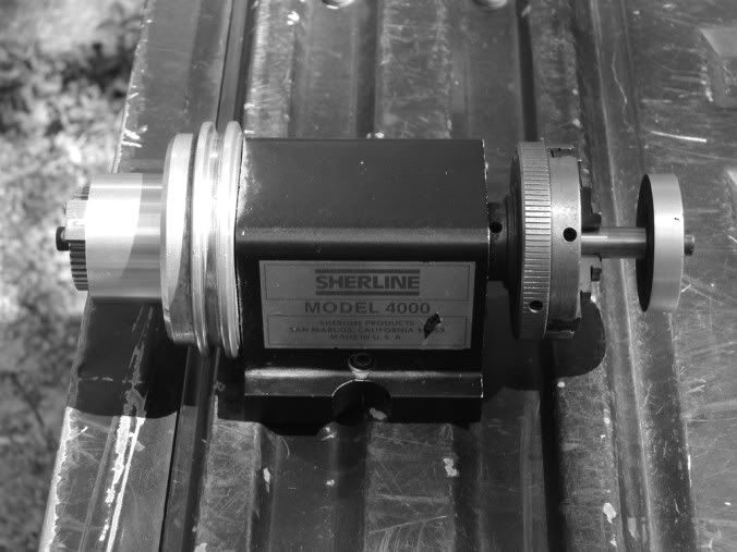
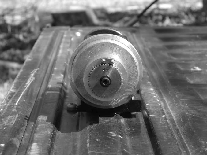
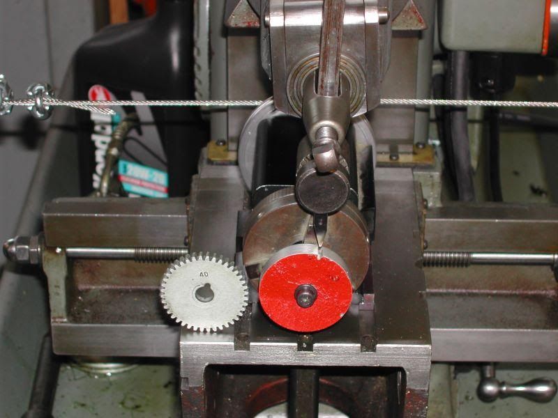
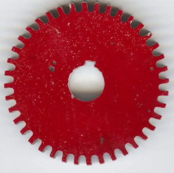
A bit of study of the patent drawings shows that it would be possible to make a bevel gear attachment for a shaper in the home shop. I have generated a spur gear using the method in my shop. I was not all that happy with the results but the disappointing result was a learning curve. I will post some photos of that attempt and I might even give it another go to fix where I went wrong.
An explanation of the spur gear generaton process with a shaper can be found here:
http://myweb.tiscali.co.uk/remark/pages/workshop/projects/geochuck1.html
The bevel gear generation method is very similar. In the spur gear method a drum with the diameter of the pitch circle is attached to the same spindle as the gear blank. A wire cable is wrapped around the pitch circle drum and both ends are attached to something solid. As the shaper table is moved the gear blank rotates the same distance along the pitch circle and the one tooth rack mounted in the shaper clapper generates a proper involute curve.
The bevel gear arrangement is very similar only instead of a cylinder for the pitch circle and a linear table a cone is needed that rotates on a rotary table. The one tooth rack in now a one tooth crown gear that generates the bevel gear.
Hugo Bilgram also invented a very useful valve gear diagram, which I find much simpler to use and understand than a Zeuner diagram. Bilgram's valve gear diagram is in several slide valve gear books and I finally tracked down a copy of "Slide Valve Gears" by Hugo Bilgram ME 1878. This is available on the web but I like real books to study from.
http://www.archive.org/details/slidevalvegears00bilggoog
I have a few engravings of Bilgram machines and I will post the images soon but the first Bilgram patent is the key to understanding the machine.
I uploaded an article about the Bilgram bevel gear machine that is from the American Machinist May 9 1885.
Dan


![MeshMagic 3D Free 3D Modeling Software [Download]](https://m.media-amazon.com/images/I/B1U+p8ewjGS._SL500_.png)


