Big Flywheel--Little Chuck

Home Model Engine Machinist Forum

Help Support Home Model Engine Machinist Forum:

This site may earn a commission from merchant affiliate links, including eBay, Amazon, and others.

Brian Rupnow

Design Engineer
Project of the Month Winner
Joined
May 23, 2008
Messages
15,298
Reaction score
8,577
Location
Barrie, Ontario, Canada
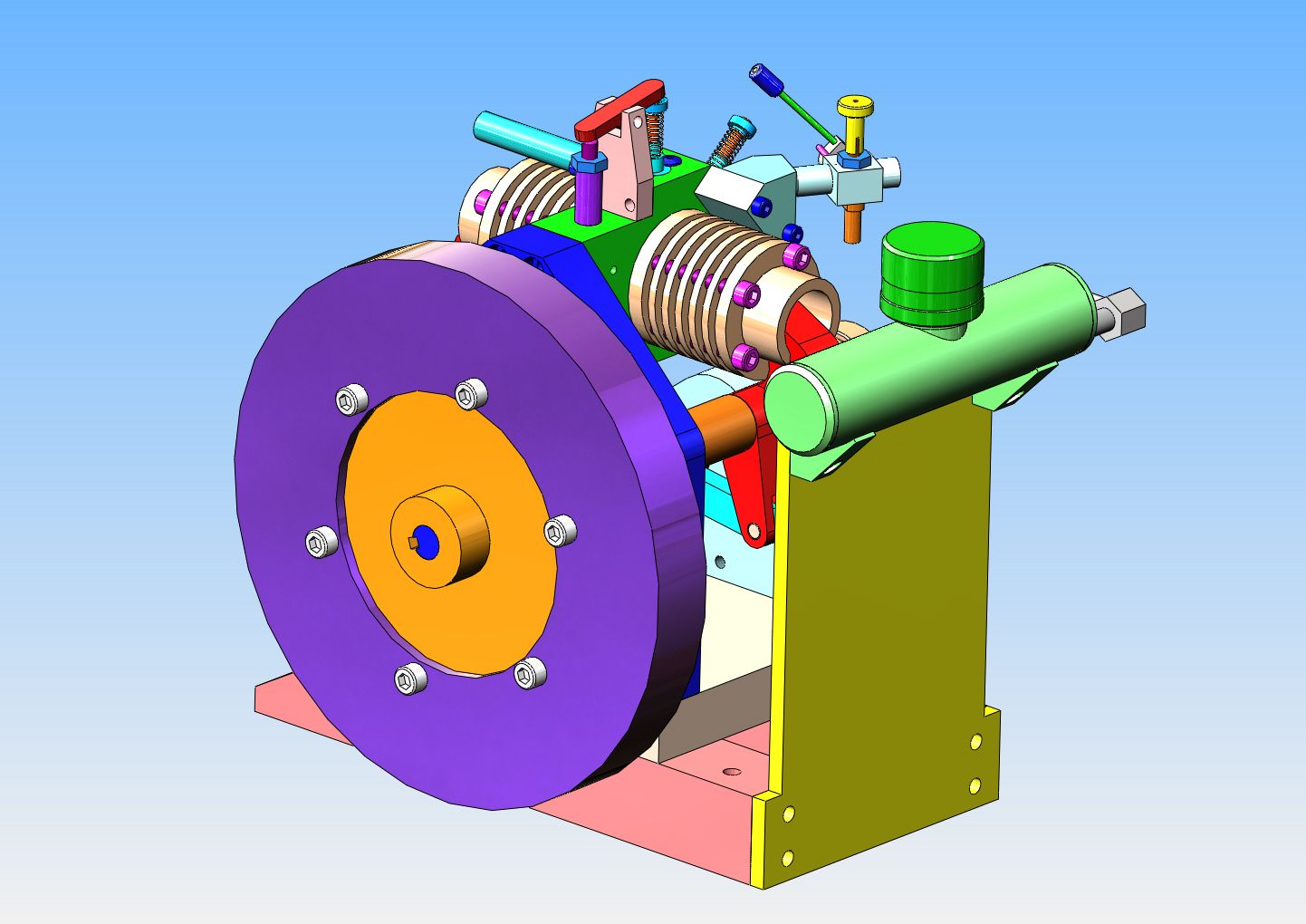
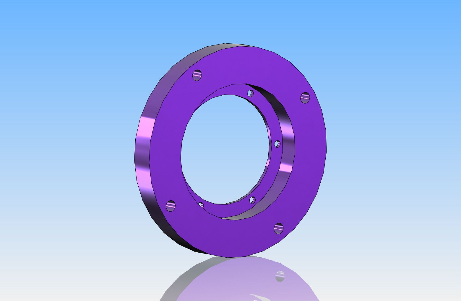
This post isn't going to dwell on anything new or marvelous. However, some may find it interesting. I want to increase the diameter of the flywheel on the opposed piston engine I designed and built. I had originally built it with a 3 7/8" diameter flywheel, but found that it wasn't heavy enough. I had built in constraints that kept me from making a larger flywheel at the time, so I made it much thicker instead. This helped, but although the engine now runs, it still doesn't run as slow as I would like. I decided to keep the original flywheel, but add a 3/4" thick x 6" diameter ring to it, as the models show. Now what makes this interesting is that the largest diameter I can hold in my chuck is 4 1/4". This post will show how I managed to get around that obstacle.

 
My lathe is listed as being a 10" x 18", and although the chuck capacity is rather limited, it did come with a 9 1/2" faceplate that I have seldom used. I decided I could do my machining by utilizing the faceplate--the only issue was centering everything. The faceplate has a machined 50mm diameter center hole in it. The piece of laser cut plate that I purchased was 6 1/16" o.d. x 2 13/16" inner diameter. I decided that by machining a piece of 5/8" aluminum plate so it would be a "precision" fit in the faceplate, and also a "precision" fit in the steel blank center hole, that would get the plate centered for a start.

 
This was the piece of laser cut mild steel plate. I went to 3 shops for quotes. One shop wanted $42, one shop wanted $20, and one shop said they would trade it for the design of a couple of metal saw horses. (which took about half an hour.)
 
I didn't want to mount the plate directly to the face of the faceplate, because I wanted to machine a clean up of the outer diameter of the plate but not cut into the faceplate. I was fortunate enough to have some 0.100" aluminum plate laying around, so I sawed it out to act as a spacer between the flywheel to be and the faceplate.
 
Now I was able to clean up the outer diameter without cutting into the faceplate, and still have everything centered. There was a fair bit of run-out in the laser cut plate, but it totally cleaned up at about 6.014" diameter. I had specified that it be cut to 6 1/16" diameter to allow enough for the clean up machining to still leave me a full 6" diameter part.
 
By reaching in from the far end of the hollow headshaft I was able to "pop" out the aluminum centering plate, thus leaving access to bore the center out to where I want it. The laser cut plate is still centered, as the four bolts which are holding it in place on the faceplate haven't been loosened off to remove the centering plate.
 
So--There we go!! All "Easy Peasy, lemon squeezy!" Will it make the engine run slower/better? That remains to be seen. According to flywheel theory it definitely should. This afternoon I will find out.

 
Nice write-up. I have a faceplate for my Logan lathe but have rarely used it.

I'll be interested in seeing how the larger flywheel affects the engine's operation.

Chuck
 
Chuck--It made a major difference. You can see the most recent post of the engine running with the big flywheel over on my opposed engine post.---Brian
 

Latest posts

Back
Top