You are using an out of date browser. It may not display this or other websites correctly.
You should upgrade or use an alternative browser.
You should upgrade or use an alternative browser.
Back to the Minnie
- Thread starter don-tucker
- Start date

Help Support Home Model Engine Machinist Forum:
This site may earn a commission from merchant affiliate
links, including eBay, Amazon, and others.
- Joined
- Nov 14, 2009
- Messages
- 675
- Reaction score
- 104
Thanks Bob but I don't think the Misses would call it sexy ;D
Don
Don
- Joined
- Nov 14, 2009
- Messages
- 675
- Reaction score
- 104
Thanks for your kind comments and thanks for looking
Don
Don
![DreamPlan Home Design and Landscaping Software Free for Windows [PC Download]](https://m.media-amazon.com/images/I/51kvZH2dVLL._SL500_.jpg)
$0.00
DreamPlan Home Design and Landscaping Software Free for Windows [PC Download]
Amazon.com Services LLC

$519.19
$699.00
FoxAlien Masuter Pro CNC Router Machine, Upgraded 3-Axis Engraving All-Metal Milling Machine for Wood Acrylic MDF Nylon Carving Cutting
FoxAlien Official

$40.02
$49.99
Becker CAD 12 3D - professional CAD software for 2D + 3D design and modelling - for 3 PCs - 100% compatible with AutoCAD
momox Shop

$24.99
$34.99
Bowl Sander Tool Kit w/Dual Bearing Head & Hardwood Handle | 42PC Wood Sander Set | 2" Hook & Loop Sanding Disc Sandpaper Assortment | 1/4" Mandrel Bowl Sander for Woodturning | Wood Lathe Tools
Peachtree Woodworking Supply Inc

$24.99
$27.99
HOZLY 5PCS/Lot ISO30 Tool Holder Clamp Flame Proof Rubber Claw CNC Machines Automatic Tool Changer
HOZLY

$12.56
$39.95
Complete Plans for Building Horse Barns Big and Small(3rd Edition)
ThriftBooks-Atlanta

$99.99
AHS Outdoor Wood Boiler Yearly Maintenance Kit with Water Treatment - ProTech 300 & Test Kit
Alternative Heating & Supplies

$89.99
Outdoor Wood Boiler Water Treatment Rust Inhibitor- AmTech 300 & Test Kit
Alternative Heating & Supplies

$29.95
Competition Engine Building: Advanced Engine Design and Assembly Techniques (Pro Series)
Amazon.com Services LLC

$94.99
$109.99
AHS Woodmaster 4400 Maintenance Kit for Outdoor Wood Boiler Treatment
Alternative Heating & Supplies

$39.99
$49.99
Sunnytech Low Temperature Stirling Engine Motor Steam Heat Education Model Toy Kit For mechanical skills (LT001)
stirlingtechonline
- Joined
- Nov 14, 2009
- Messages
- 675
- Reaction score
- 104
Beginning to look a bit like a Traction engine now.
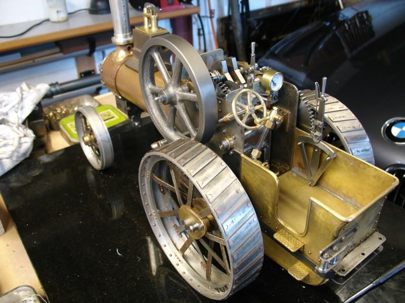
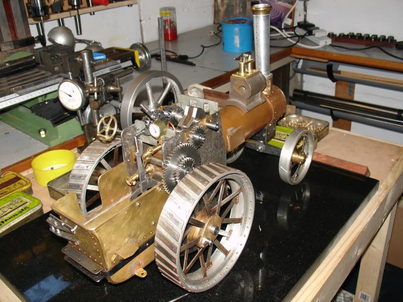
I'm getting all excited,some tricky bits comming up next,water pump,cylinder,brake gear.


I'm getting all excited,some tricky bits comming up next,water pump,cylinder,brake gear.
- Joined
- Jun 4, 2008
- Messages
- 3,294
- Reaction score
- 636
Checking progress from the Istanbul airport lounge; looking real nice! 
- Joined
- Nov 14, 2009
- Messages
- 675
- Reaction score
- 104
Hi ,the eccentric thingy is the wheel drive pin,just a round pin with a knob on it to engage drive,I think that is what you mean.Henk said:Don,
Indeed looking very good.
Out of curiosity, what is the function of the eccentric thingy on the back wheel?
Regards,
Henk
Don
Its comming along nicely, that pressure gauge is definately the right size, a 1" would have been too large. The cylinder is where the fun starts - so many holes - such small taps 
Henk The hubs have the teardrop profile to avoid weakening them where the drive pins are inserted. Thes epins give the option of having an open or locked diff on engines equiped with a diff or in the minnies case you can drive just on erear wheel for manovering in tight spaces.
On the other side of the engine, inboard of the wheel is a "winding drum" this is a large pully that carried a steel cable for winching, again the pins are used to remove drive from the wheels and just have the axle turn the drum.
On a few of the larger engines such as Road Locos they had double pins and the hub was shaped accordingly as you can see from these castings
Jason
- Joined
- Nov 14, 2009
- Messages
- 675
- Reaction score
- 104
Come on kvom get back in that workshop there is a paddle engine waiting for you ;Dkvom said:Checking progress from the Istanbul airport lounge; looking real nice!
Don
Jason.You answered that much better than I ,thanks
Don
- Joined
- Nov 14, 2009
- Messages
- 675
- Reaction score
- 104
This is my setup for machining the cylinder saddle.I used a dti to centre the mandral then moved to the correct offset using the dro.setting the boring head to the correct radius before hand.
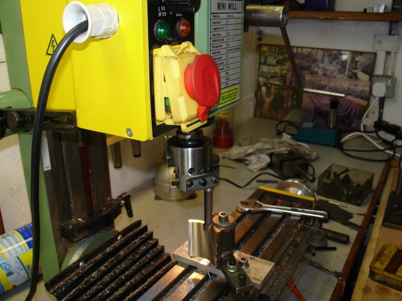
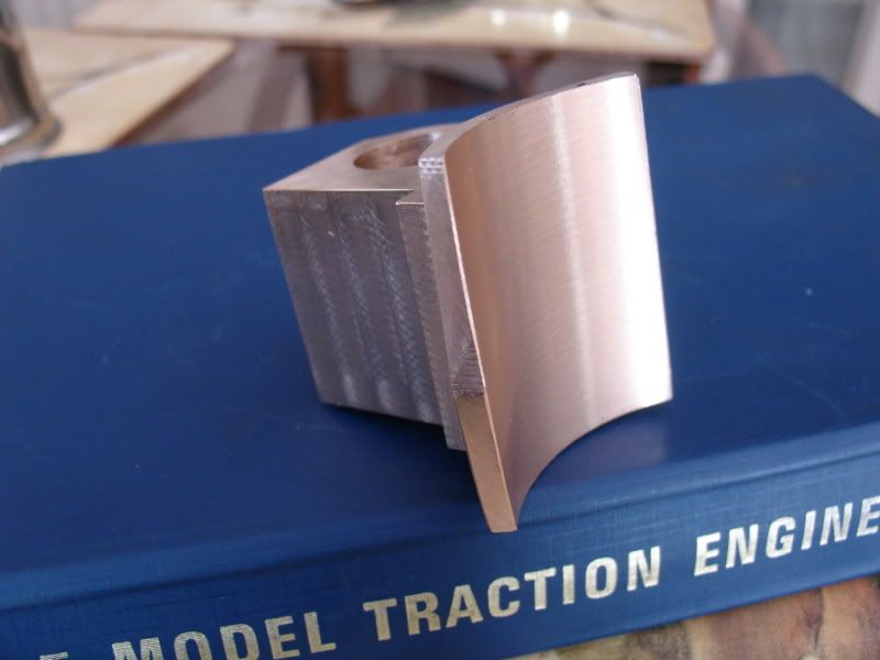
Please don't look to closely at my hi tec handle on the z axis,but it worked well so I shall make a nice permanent one later,I machined the rest of the cyl by mounting the mandral on an angle plate horizontaly.
Don


Please don't look to closely at my hi tec handle on the z axis,but it worked well so I shall make a nice permanent one later,I machined the rest of the cyl by mounting the mandral on an angle plate horizontaly.
Don
- Joined
- Nov 14, 2009
- Messages
- 675
- Reaction score
- 104
Here is the progress to date,I can see the end in sight but still a month or so yet.
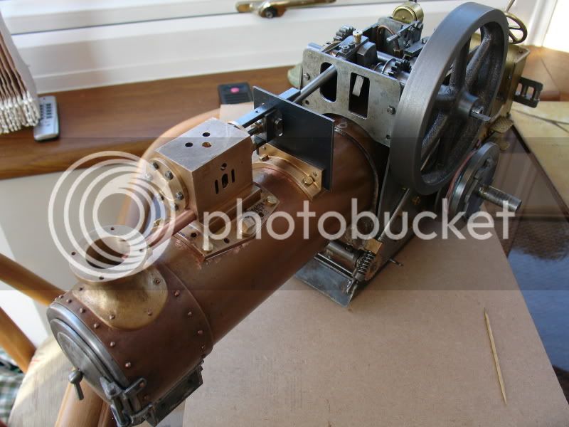
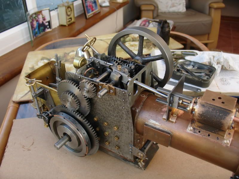
I thought maybe someone might be intersted in my method of centering a centre pop in the lathe.
I held a piece of 5/16" silver steel or drill rod in the collet and turned a 60 deg point then turned 1/4" along the length from the point,faced and centered the other end,I just pop the pointed end in the centre pop on the job and a running centre exerting enough pressure to make the rod turn
then DTI the turned bit,works a treat.and cheapo.
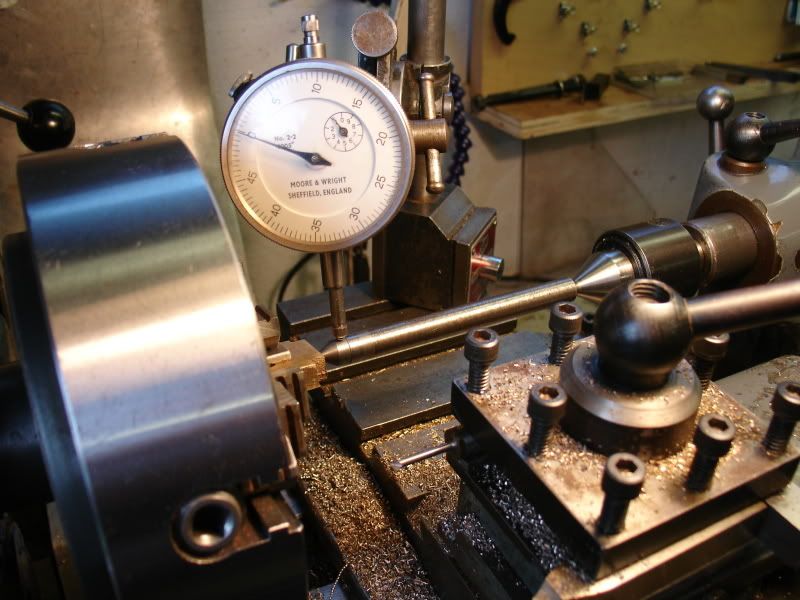
Don


I thought maybe someone might be intersted in my method of centering a centre pop in the lathe.
I held a piece of 5/16" silver steel or drill rod in the collet and turned a 60 deg point then turned 1/4" along the length from the point,faced and centered the other end,I just pop the pointed end in the centre pop on the job and a running centre exerting enough pressure to make the rod turn
then DTI the turned bit,works a treat.and cheapo.

Don
Its comming along well, you will have a busy month ahead :
Jason
Jason
- Joined
- Nov 14, 2009
- Messages
- 675
- Reaction score
- 104
Cheers Jason,I have been told that i am obsessed with it,so I have to take it easy.
Don
Don
- Joined
- Nov 14, 2009
- Messages
- 675
- Reaction score
- 104

Ready for mounting on the boiler,
Don
zeeprogrammer
Well-Known Member
- Joined
- Mar 14, 2009
- Messages
- 3,362
- Reaction score
- 13
That is just beautiful Don. Really a piece of art. I just saw an earlier picture and the detail is just awesome. Just awesome.
- Joined
- Nov 14, 2009
- Messages
- 675
- Reaction score
- 104
Thanks Zee,you made my day,I didn't think anybody looks at my posts.
Don
Don
Similar threads
- Replies
- 11
- Views
- 922
- Replies
- 22
- Views
- 2K
- Replies
- 11
- Views
- 1K


![MeshMagic 3D Free 3D Modeling Software [Download]](https://m.media-amazon.com/images/I/B1U+p8ewjGS._SL500_.png)


