Anvil Fever

Home Model Engine Machinist Forum

Help Support Home Model Engine Machinist Forum:

This site may earn a commission from merchant affiliate links, including eBay, Amazon, and others.
I had significant bed lifting problems when I used a flexible magnetic bed. I had a banana shaped base on all my prints. Going to a solid base helped but I suspected that my drafty shope was not helping either. I purchased a commercial enclosure for my printer and no longer have base lifting problems. With the addition of a strip of led lights the enclosure makes a nice printing station.
I was considering a heated enclosure for my printer, but was warned that I could overheat the power supply and electronic module.

I think a non-heated enclosure would help keep any drafts away from the heated bed (my printer bed is heated).

I will probably just make a wood frame, and wrap some 24" wide stretch wrap around it.
I don't really need a fancy printer enclosure, and I don't really need a permanent enclosure either.
Perhaps a folding enclosure.

.
 
Pat in the same way you toggle on/off your draft angles that were added at the end you simply sketch the material to be machined off the casting and extrude cut that and then you can toggle the cuts on/off so the one 3D modeled part will show the pattern or the finish machined part simply by where you leave the bar down the left hand side, 2D drawing will be produced from where that bar is down the left side so I can easily produce a drawing of teh pattern and a drawing of the finished part
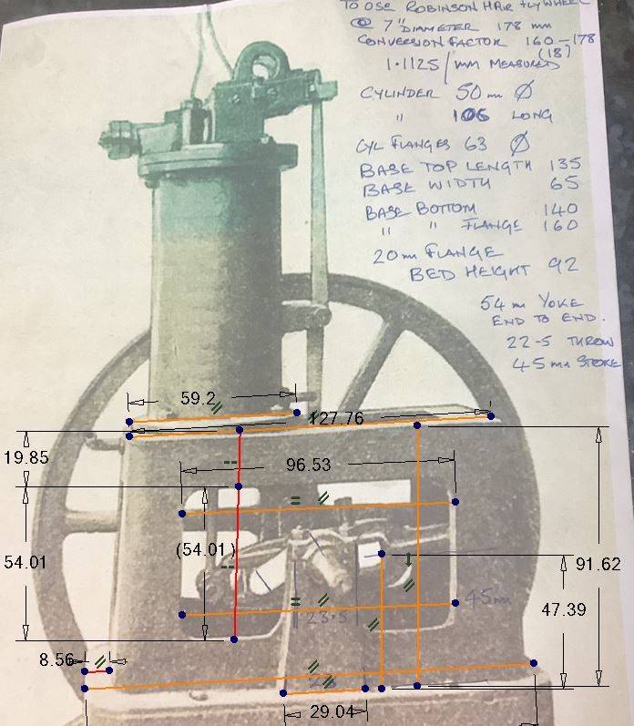
I could see where that could be done, but my approach to creating a 3D model for an engine is to first find some photos of an old engine, then pull those photos into AutoCad, trace over the raster images to create some basic geometry, pull that geometry into Solidworks, and extrude the basic shapes of the engine parts.

You method seems to work backwards to subtract out machining allowances, and I have no idea how I would work backwards like that to arrive at the dimensions I want.

The dimensions I want to use are incorporated into the initial AutoCad 2D sketches, and are the "as-machined" dimensions.

I am still studying your method, to make sure I understand all the implications of it.

.
 
As far as making core boxes as you have done, I am thinking all that work is totally unnecessary, and wasted effort......not to be critical of your method, but just thinking outloud.

Sometimes the use of coreboxes centers around the type of molding sand used, and if greensand or petrobond is used, coreboxes may be necessary.

For bound sand using either a resin or sodium silicate, I think I would have created your base pattern with the openings using either a 3D printer or CNC, (no coreboxes), temporarily closed off the windows/openings, rammed the interior and let it set, then rammed the exterior mold halves.
This is a method I have used to avoid having to make coreboxes.

I just don't see any reason at all for the coreboxes.
Smarter, not harder, as they say.

So in essence, your pattern becomes your corebox.

(Jason B's photo below).

Edit:
I suspect Jason used coreboxes because it lends itself well to a CNC approach.
For a 3D printed approach, I would not bother with making coreboxes, but rather just used the 3D printed base as the mold halves and corebox.

I don't have a CNC machine, and so I don't even consider CNC solutions like Jason uses.
I always think a 3D printed solution to pattern making, since that is the equipment I own.
.

Image59.jpg
 
Last edited:
Round hole can simply be drilled and just core the square one.

If you intend to make a match plate with 10 or 12 pattens on it then having to remove existing lettering, make good and then add new lettering would be time consuming. Even worse if someone comes back and askes for a second batch as you would have to redo it all again. Same would apply to just casting one at a time, it will be easier to just change the insert plate and you can keep them if more of the same text are ever needed

So if you print a recess say 1/16" deep into the side of the pattern you can then simply place a flat plate with the new lettering on into the recess. If that plate were say 1/8" think it would have the raised surround and the letters standing out from that. You could either print it complete with letters or simply use 1/8" thick plastic or aluminium and glue separate letters in place. Letters could be 3D printed, pattern makers letters or smaller "Slater's letters"

Here is a quick anvil with exaggerated draft
I agree this is a good idea.

I think a drop-in logo would be ideal, although as I said, the flat part around the lettering would have to be filled/puddled with something to smooth out the 3D printed lines.

I made up a plaque for FIRE, and now the date is wrong for use at future FIRE events (this is a local art-iron event).

RImg_3736.jpg
 
After thinking about Jason's method for extruding out extra material, and then cutting back to a machined dimension, I would find this approach tedious, if not difficult.

I don't necessarily use the same amount of machining allowance everywhere, and an additive process seems far more easy than a subtractive process, since you start with as-machined dimensions.

I guess it boils down to personal preference, and what works best for the individual and the machines/process/approach they want to take.

And this illustrates that there are many workable approaches to any engine modeling/pattern making/molding/casting endeavour.

Sometimes I use a hybrid approach, and mix and match within a given mold.

I typically use methods that are easiest, and methods that work consistently, until I discover a better method, and then I adopt or modify my method.
My methods and materials have definitely evolved over time, and they are still evolving as we speak.

.
 
Last edited:
Fun project. I'm also a hobbyist blacksmith and knife maker. Be careful, once you find your first anvil, ever larger ones start coming out of the woodwork :)

As for material, I would use what casts most easily for you. Cast iron will not make a particularly effective anvil in any form, so these will be largely ornamental. I do have a small one about that size that I find useful for peening small rivets when I am making pocket knives.

Here is a pic of my primary anvil in use :)
 

Attachments

  • IMG_20160819_191308022.jpg
    IMG_20160819_191308022.jpg
    881.4 KB
pat, I do it your way too - modeling the part and then adding machining allowance and draft, just depends on the particular part and what method works best.

I do also use trace but unless you have a good square on image which is not always the case it can just be better to draw lines between features and use their lengths as a basis. This was how I got the measurements to work with on that part

lo6.JPG


As for core boxes your method may well be better for the home foundry but as these were farmed out for casting it was simpler and quicker therefore cheaper to do it with a core box as there were several cast and if we want more will not have to pay to cover all the holes each time some more cores are needed. You would also need some way to close off the holes when ramming the pattern, plus there is no parting line along the outside ends of the pattern doing it with the corebox as the pattern does not need to be split to allow the core to be extracted..
 
Cast iron will not make a particularly effective anvil in any form, so these will be largely ornamental.
Yes, I agree.
The steel I have heard about in the good anvils is legendary, as is the bounce test.

Unfortunately steel is in the real of induction furnaces, and a large knowledge of metalurgy.

Nice forging you have there !

.
 
pat, I do it your way too - modeling the part and then adding machining allowance and draft, just depends on the particular part and what method works best.

I do also use trace but unless you have a good square on image which is not always the case it can just be better to draw lines between features and use their lengths as a basis. This was how I got the measurements to work with on that part

lo6.JPG


As for core boxes your method may well be better for the home foundry but as these were farmed out for casting it was simpler and quicker therefore cheaper to do it with a core box as there were several cast and if we want more will not have to pay to cover all the holes each time some more cores are needed. You would also need some way to close off the holes when ramming the pattern, plus there is no parting line along the outside ends of the pattern doing it with the corebox as the pattern does not need to be split to allow the core to be extracted..

Yes, very good point about coreboxes, and having a foundry make multiple castings.
I pretty much work in a vacuum in my backyard foundry, often with one-off castings.

The three green twin photos I used were all skewed, and so it was a bit tricky to find some reasonable dimensions, but it can be done.
I think my first attempt to extract dimensions was to superimpose a grid over the photos.

Now days I pretty much do the same thing Jason is doing in 2D, to get the geometry worked out.

The Frisco Standard photos are pretty much the same way, ie: skewed, but again, you can still extract the data if you are careful.

Great job on that engine and those iron castings.

Making iron castings for old engines is the cat's meow in my opinion.

Edit:
For skewed photos, one can sketch like Jason has done above, and sort of average things out, or you can just draw one side of a symmetrical shape, and then mirror the sketch.

.
 
For the sake of discussion, I will think through how I would mold this part, without using a corebox.

Jason's coreboxes are admirable work to say the least, but for those who don't want to make or use coreboxes, here is an alternate method.

I would make two pattern halves, using a 3D printer.

I would place one pattern half face down on the molding board (pattern half shown below).

Lightly clamp a board across the bottom, side and top to close off the holes.

Ram the interior with sodium-silicate bound sand, and set with CO2, or use a catalyst.

Break the bond between the core and the pattern half by rapping lightly, but keep the core in the pattern.

The pattern half would need to be doweled into the molding board.

Scrape off the bound sand in each window flush with the exterior surface of the pattern, using something that won't damage the pattern, like a wood straight edge.

Place the flask over the pattern half/core.

Ram the flask.

Remove the core.

Remove the pattern.

Repeat for opposite side of the pattern.

Dowel one core into the other, and adhere with core cement.

Perhaps dowel the core into the mold halves in a few places.

Insert the core into the molds and close the flask.

So no core boxes needed, and this would be a method routinely used in foundries for mass production (limited runs, not high volume).


94195-otto-face-cuts2.JPG
 
Last edited:
There was an article that I have seen, which illustrates how lathe beds were cast, and it seems like they used a similar method as I show above, since there is a window in the top of lathe beds.
I can't find the article unfortunately, but if I find it, I will post it.

.
 
As there is no draft at the ends of the part you may have a job pulling the two halves out of the sand. It was cast upright with the flask joint being the bottom edge of the flange so all draft was so it could be pulled vertically not sideways.
 
Last year I made a miniature blacksmiths anvil. I drew it on Solidworks like you and so machined it entirely from solid material. I placed the anvil on a suitable wooden stand and made the same scale wooden handle hammer and pliers. Maybe it can give you some humble ideas. You can watch all process on my youtube video linked below.

 
Kevork-

That is a very nice mini-anvil.
And I watched your 3D modeling video, and learned some new methods that I was not aware of.
I really learn a lot from the feedback of others about 3D modeling.

And a great lobster boat build too.
I have one of those on my list of things to build.

This is Kevork's RC lobster boat.
How cool is that?

 
Thank you Green Twin for watching and liking my videos and also for your valuable comments. I've been using Solidworks since 2009 to model some fittings or valves and then produce press molds in a factory. Although I usually do solid modeling, I also tried some surface modeling for my self. Especially when modeling surfaces, I use three-view drawings called "blueprint". Please feel free to ask me anything, I will try to help to the best of my knowledge.

Also thank you for highlighting my Lobster boat project, it seems there are still some deficiencies and under constructions, such as navigation lights, roof and roof lights, cleat rope attachment points and some accessories...
 
Love your work, I am introducing this same concept with an anvil to my class next year. They will take a drawing, design it in either solidworks or inventor, print it out, mould it then cast it. As more and more foundries are starting to introduce 3d printing either as a pattern or as a completed ready to pour mould, I feel it's important to give the apprentices an understanding of the whole process..
 
Back
Top