Another Kerzel

Home Model Engine Machinist Forum

Help Support Home Model Engine Machinist Forum:

This site may earn a commission from merchant affiliate links, including eBay, Amazon, and others.

///

Simon
Joined
Sep 19, 2011
Messages
470
Reaction score
63
Well, I've finally started cutting metal for my Kerzel that I started planning 6 years ago!

I got most of the way through 3D modeling and converting to metric, but then life got in the way; a new job (been there 5 years now and have somehow survived two rounds of redundancies :shrug:) and as of three years ago, a new family :eek:

Now that the young'n can actually entertain himself for a while and doesn't need constant attention, and also because I'm tired of armchair modeling, I've been trying every day to get some time in the workshop no matter how short.

So, here is my attempt at a build log. As far as taking photo's goes, well it's something I'm going to have to get used to. I have a few here, but will try for more as I go along.

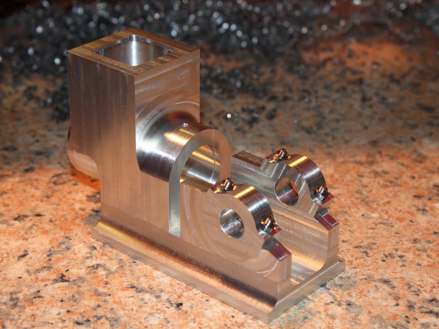
The last couple of weeks have got me this far, the base and body are done, save for a few small details that still need to be converted to metric (cam slide bearing and push rod bearing)

IMG_4805.JPG


IMG_4811.JPG
 
The chunk of Ali I used for the body was 50mm wide, but the body is only 38mm wide so some time on the bandsaw left me with this offcut that was just the right size for the bearing blocks.
Here I've penciled in rough outline to check that the notch isn't a problem, and the blocks after squaring up and selecting the best faces.

IMG_4814.JPG


IMG_4816.JPG
 
Back to the first post where I mentioned trying to find time.... yesterday I drilled a hole...

IMG_4819.JPG
 
And today I found just enough time to drill another.... :rolleyes:

IMG_4820.JPG
 
Simon--I will be watching as this develops. The Kerzel is a very nice little engine.---Brian
Hi Brian,
Yes it is a nice engine but there were a few things about it that bug me, so I've made/will make a few small cosmetic changes to mine.
First of which you may have already noticed, I'm not a huge fan of the raised lip around the top of the reservoir, so I've left this flat, more pleasing to my eye.
I'm also not going to be using any cap head screws anywhere (except under the base where they won't be seen) they just don't look right.
Hope to have the bearing blocks and caps done tomorrow.
 
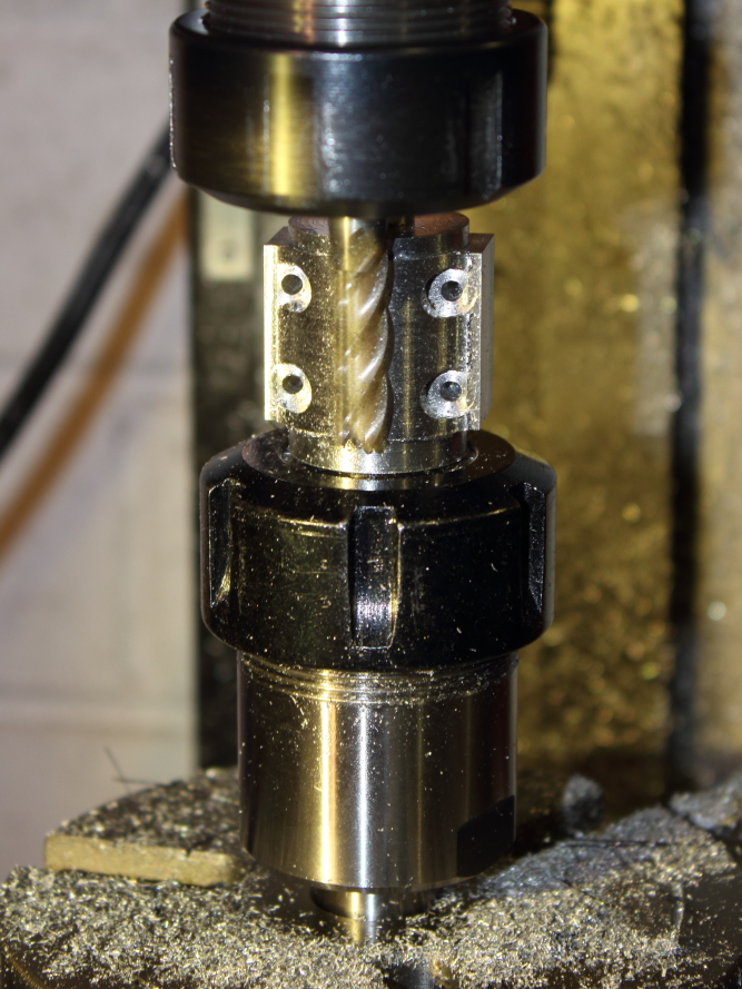
I could have done the next step in the lathe, but I would then have needed to freehand grind a round nose tool, and I suck at grinding tools.
I have a good set of ball nose milling cutters so decided that would be the best way forward.
The lathe still got used though, as I need a fixture for the rotary table to hold the bearing blocks.

IMG_4822.JPG


IMG_4828.JPG
 
From now on, I'm no longer using my camera in auto mode, it sucks.
All photo's below are manual mode, so much better.

Next job to do was to cut the angle on the backside of the bearing blocks.
This angle isn't critical, but more aesthetically pleasing if both sides are the same :D

I slid both bearings blocks onto some precision ground 12mm rod and used a small drop of superglue to hold the left and right sides to each other.

The rod was then rested on the jaws of the vice and the lot rotated until close to the needed angle.
I then used one of my 10-20-40 blocks, packed up with a 0.25mm feeler gauge to centre height of the rod so I could eyeball along the top edge of the 10-20-40 block and tweak the angle.
Once happy the vice was nipped-up, heighth set off the rod, rod then slid out and I started cutting.

IMG_4834.JPG


IMG_4840.JPG
 
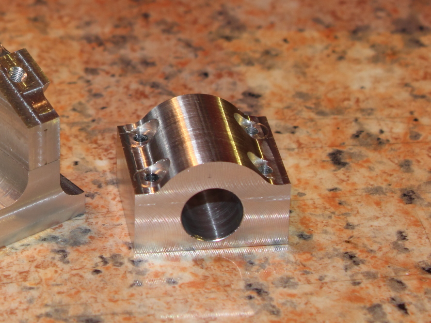
Last operation for the bearing blocks (for now) was tapping and then checking for fit.
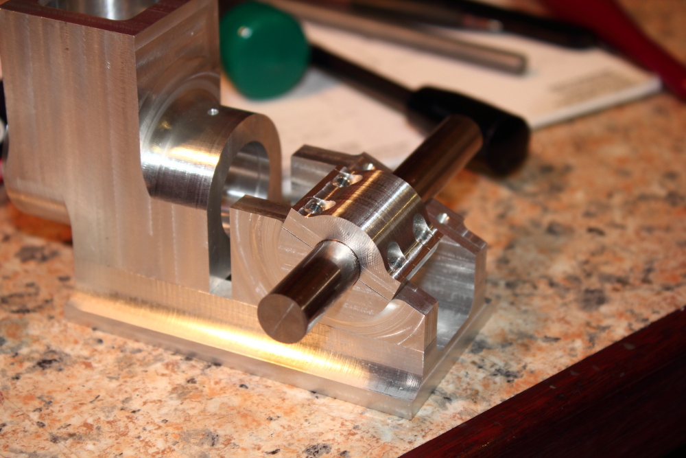
The fit was near perfect, the 12mm rod just dropped into place and there are zero gaps, check that fit in the close-up, same on both sides. Gotta be happy with that :)

Moving onwards and upwards, the bearing caps.
I found a bit of scrap mystery Ali, dressed and squared it up, picked the best faces as reference surfaces for subsequent work and decided it was beer o'clock.
Will try to get some more done tomorrow, but got a christmas lunch with the inlaws. :mad:

IMG_4850.JPG


IMG_4851.JPG


IMG_4856.JPG


IMG_4856_.JPG


IMG_4862.JPG
 
Before I start work on the bearing caps, I have a decision to make, 8mm or 7mm?

Rather than using cap head bolts, I'll be using studs and nuts, just looks nicer and isn't much extra work, well worth the time.

Problem is, the nut will be difficult to do up.
I much prefer the 7mm counterbore (on the right), but I'll never get a socket in there.
If I go with 8mm counterbore (left side) then I can probably chuck a socket in the lathe and turn it down to fit.... but the 7 looks so much better.

What to do, what to do... sleep on it.

Cap3D.jpg
 
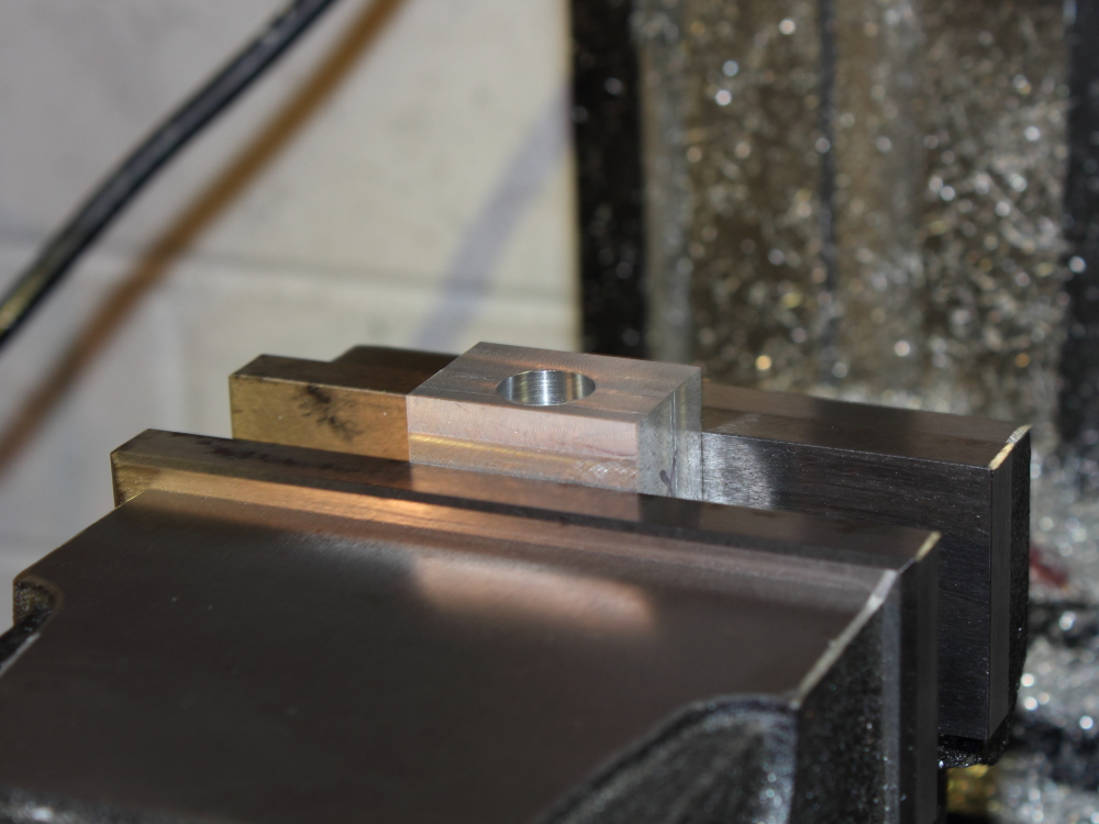
After yesterday's christmas lunch with the in-laws, I only managed enough time in the shop to drill one hole in the bearing cap blank, hardly worth a photo, however, in-case anyone has wondered about the rather rough looking finish in the left-hand bearing block, it's actually not as rough as it looks.

While trying to slide the this block over the 12mm rod before machining the angle, it would not budge, I'm guessing the part had shrunk a little and the hole was now a bee's thingy smaller.

I resorted to scraping, by sliding the block on the rod as far as it would go then removing, the rod would leave a mark where the tight contact was.
With a very sharp (new) exacto blade, I was able to shave minute amounts from the area and then test fit again, repeating the process until the block was a nice sliding fit on the rod.
The shavings were so thin that they would float away in the air currents in the room!
I've never done this before, but most certainly will again, even if it looks a bit ugly, the fit is close to perfect. (nothing IS perfect ;))

IMG_4850_crop.jpg
 
Well, that’s Christmas done for another year, I hope everyone had a good holiday!
Unfortunately I’ve not done anything further on the engine since before the Chrissy break, so I’m itching to get back into the workshop but that’s not likely until after New Year. Even then, I’m going to be busy with family stuff.
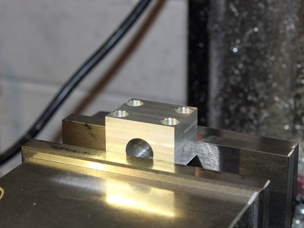
I’ve had time to drop-in and catch-up with others’ projects, but no time to post updates to my own. As mentioned in the previous post, I only managed enough time on Sunday (18th Dec) to drill one measly hole in the bearing cap blank.
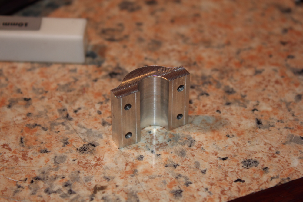
It was a similar story for the following day (Mon 19th), I found enough time after work to drill and counterbore the caps.
original.jpg

original.jpg
 
Work was quiet on Tuesday so I left early and got quite a bit done in the shop.
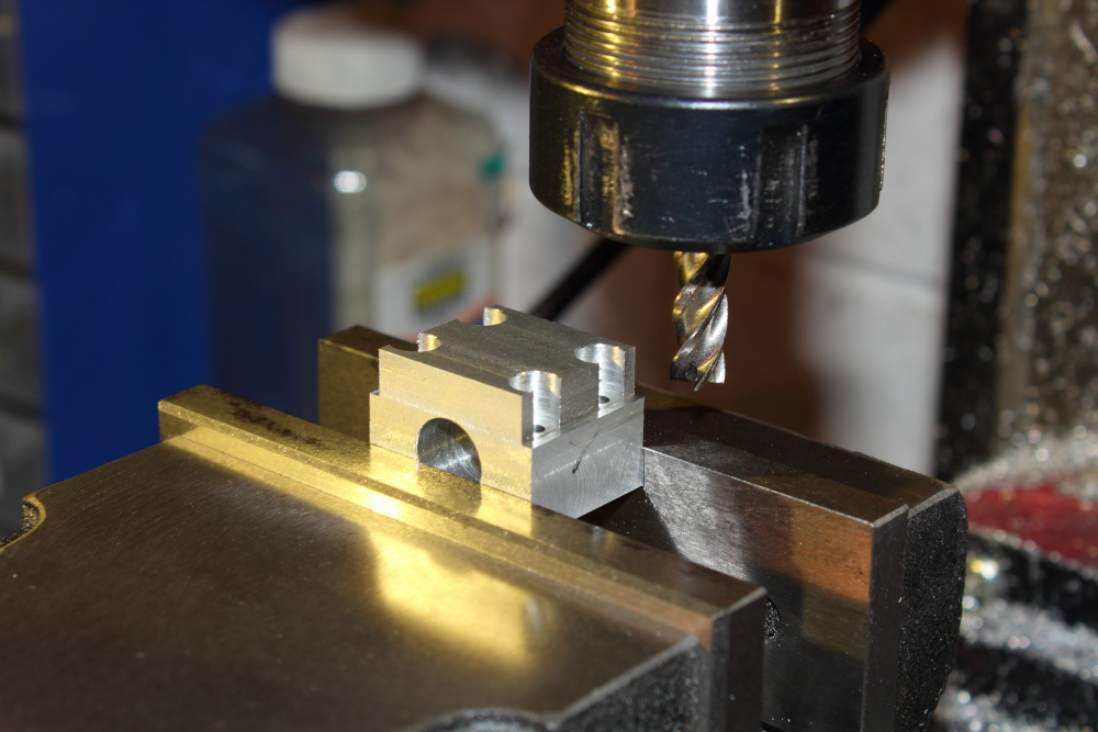
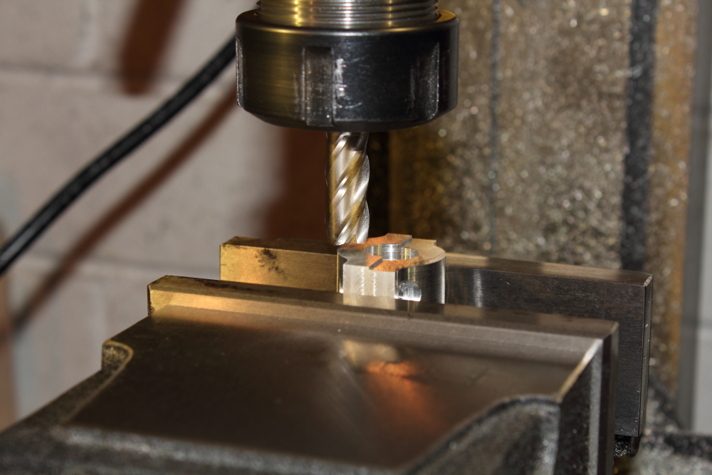
First up was milling the flats on either side of the caps. It was here that I noticed the mill needed tramming, again. One day I’ll get around to modifying this X2! I’ve only had it a decade or so :rolleyes:
original.jpg


Now the square work was done for this, it was time to remove the vice and mount the rotary table.
One day I’ll have a mill with a table big enough to have both vice and RT mounted together!
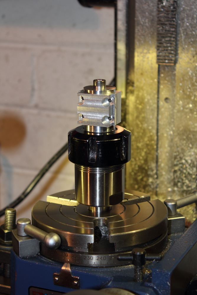
With the head trammed and RT set-up and centred, I moved over to the lathe to quickly turn-up another fixture, this time to hold the bearing blank, once done, it was chucked in the RT collet holder and the work clamped down, ready for rounding the bearing cap.
I had earlier (at work, it was very quiet!) roughly drawn the cap and milling cutter start/end positions in AutoCAD to determine the total angle I needed to turn, which measured a smidge over 105°.
original.jpg

original.jpg

original.jpg


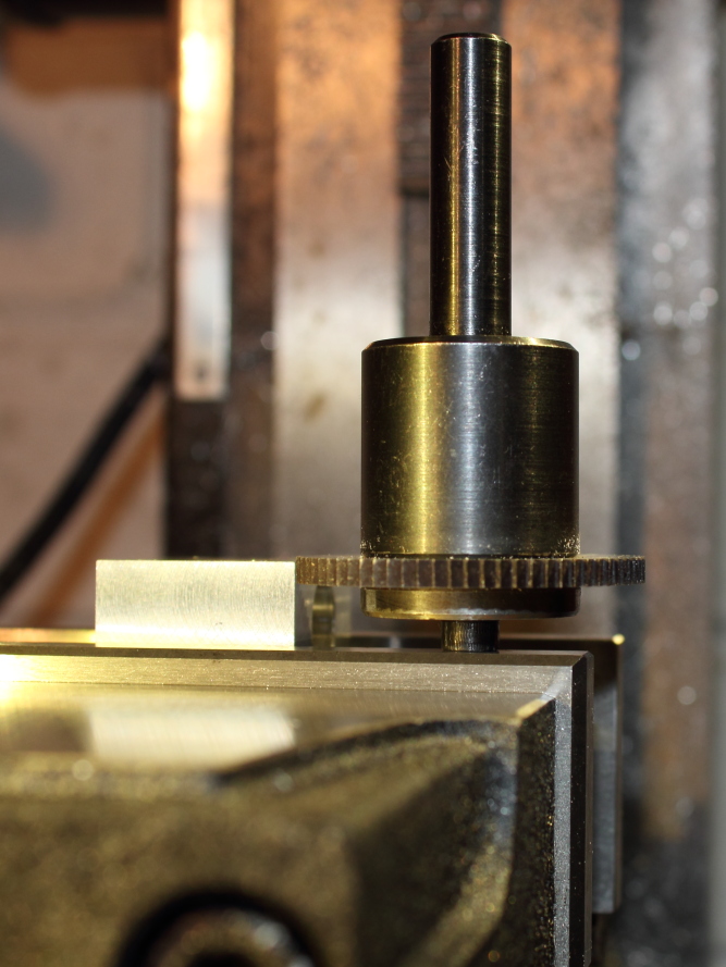
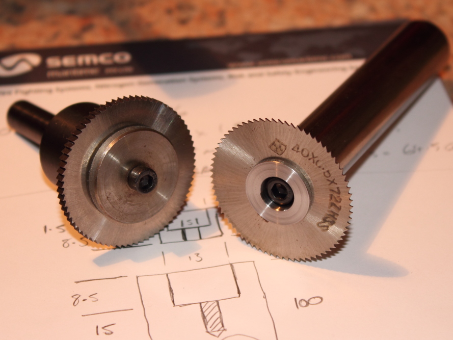
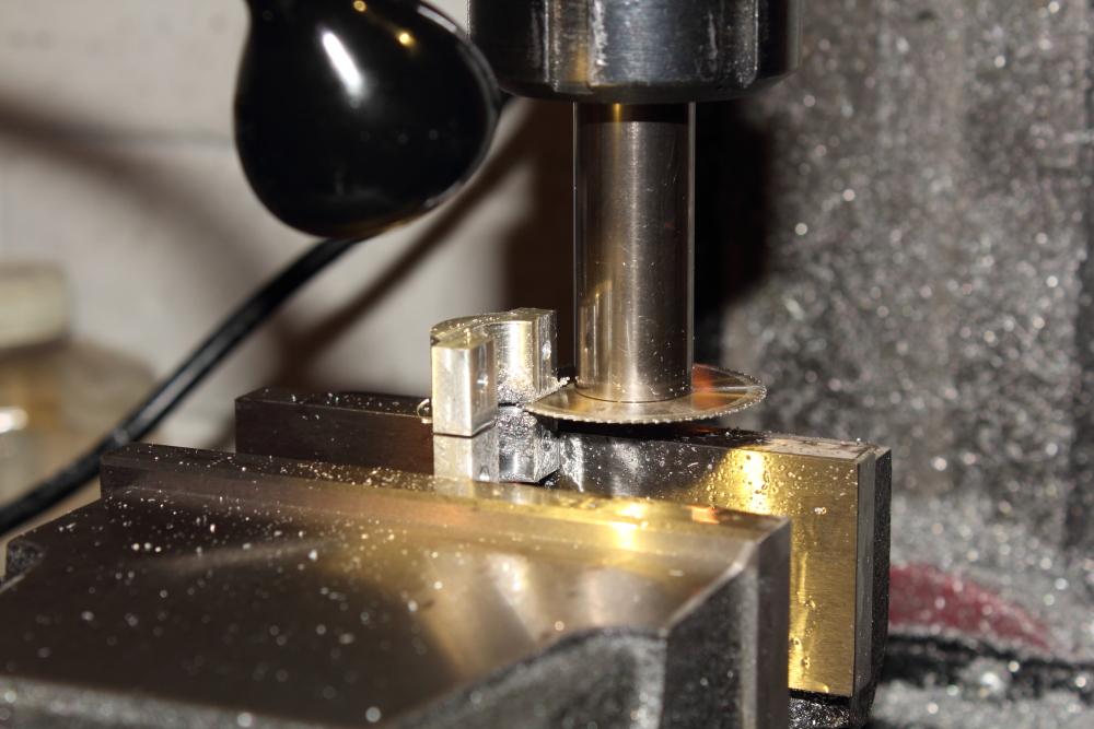
With that done, it was time to remove the RT and set-up and square the vice again (urgh!) for removing the excess material and then parting the caps. I decided to do this with the 0.5mm slitting saw but struck a problem.
original.jpg

This is a Taig (Peatol) holder I had purchased some time ago but it has never been very useful, having clearance issues of some sort almost every time I have needed to use it.
So, it was time to make a better one with less clearance issues.
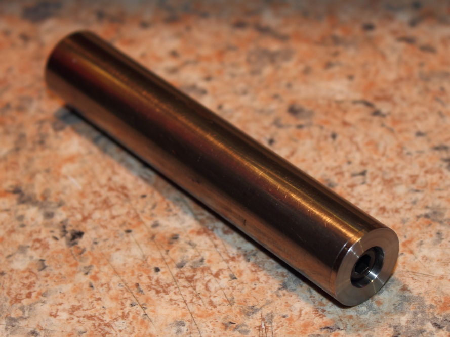
The following holder(and all the earlier fixtures) was turned from a length of 18mm (0.71”) diameter rod that machines beautifully. Unfortunately, I now only have a short stub of this left. I’m hoping I can find some more old electric typewriters I can strip down to salvage similar sized bars ;)
Old printers are also a good source of nice machinable mystery steel, but they’re rarely larger than about ½” dia.

original.jpg

original.jpg

original.jpg

original.jpg

That took care of all my shop time for Tuesday, but I was happy with what I got done.
 
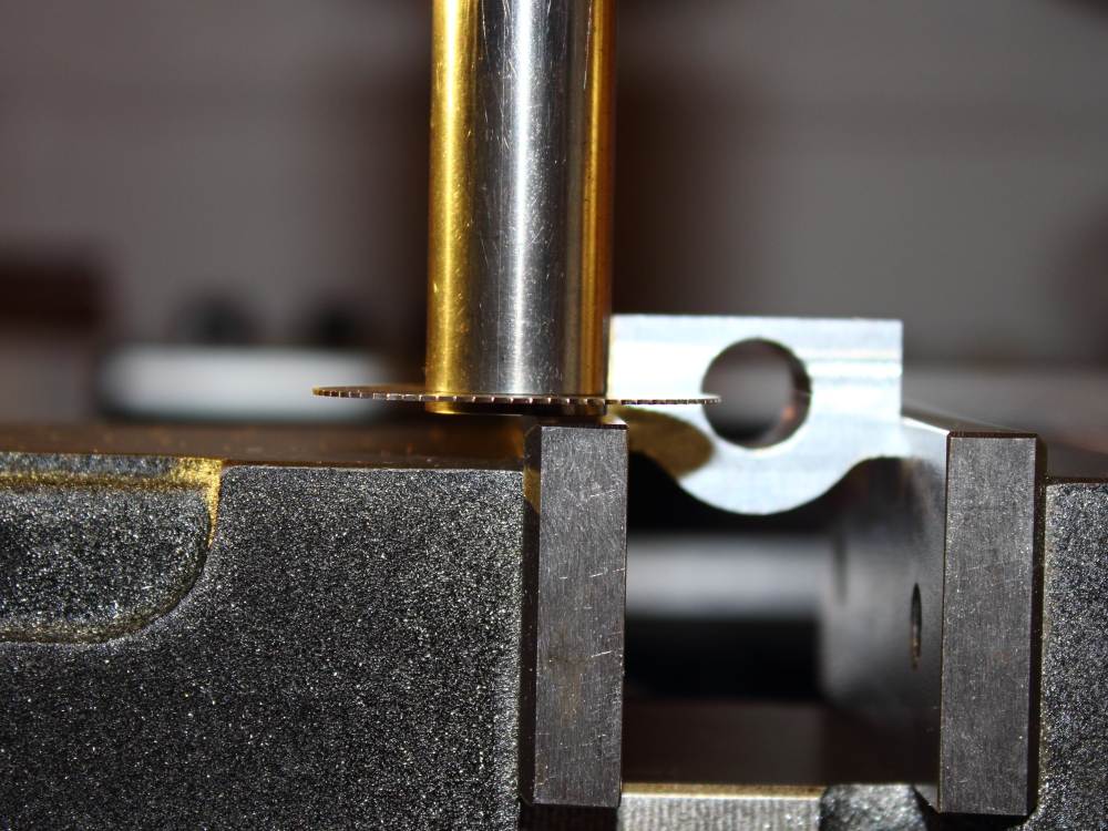
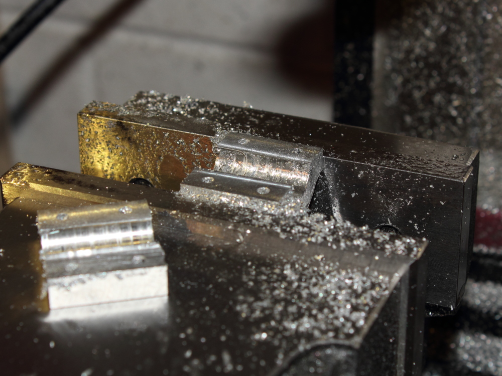
Wednesday it was time to slice off the excess material, this was quick and easy and I was surprised at how clean the saw cut was!
original.jpg

Much nicer than with the Taig holder, which I decided was due to the increased shank diameter (18mm/0.71”) making this holder far more rigid than the Taig version (9.5mm 3/8”)
It’s also nicer to use with the metric cap screw, the Taig one had some weird screw that none of my Allen/Hex keys would fit snuggly…. not even my imperial ones!
I could have sawn to finished size, but based on history with the Taig holder I thought it safer to saw oversize and finish with an endmill.
original.jpg

original.jpg


With the excess off, it was time to split the caps and reduce to final width which ended Wednesday’s shop time.
original.jpg

original.jpg

original.jpg
 
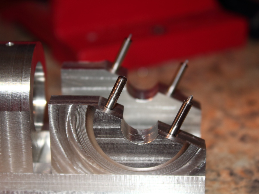
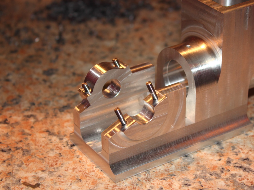
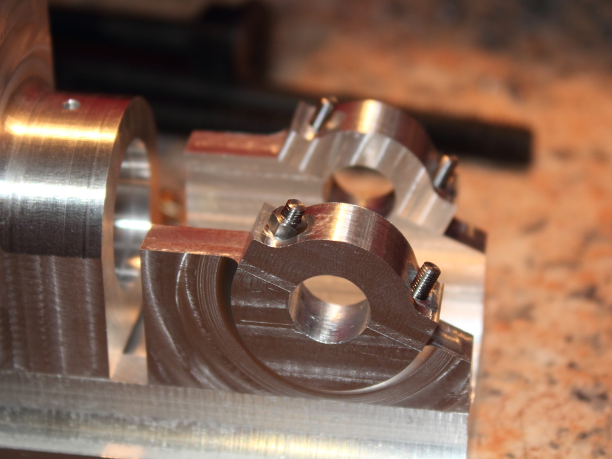
Thursday I couldn’t decide which part to make next, but looking at the trial fit I couldn’t help but think how nice it would be to see the studs and nuts in place….
For the first time in this build, I grabbed some non-salvaged, non-mystery metal from my stock.
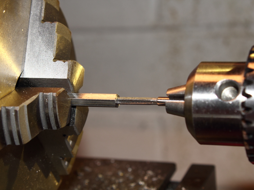
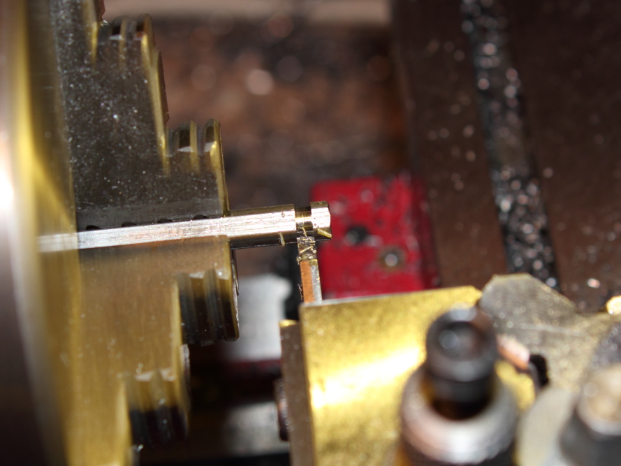
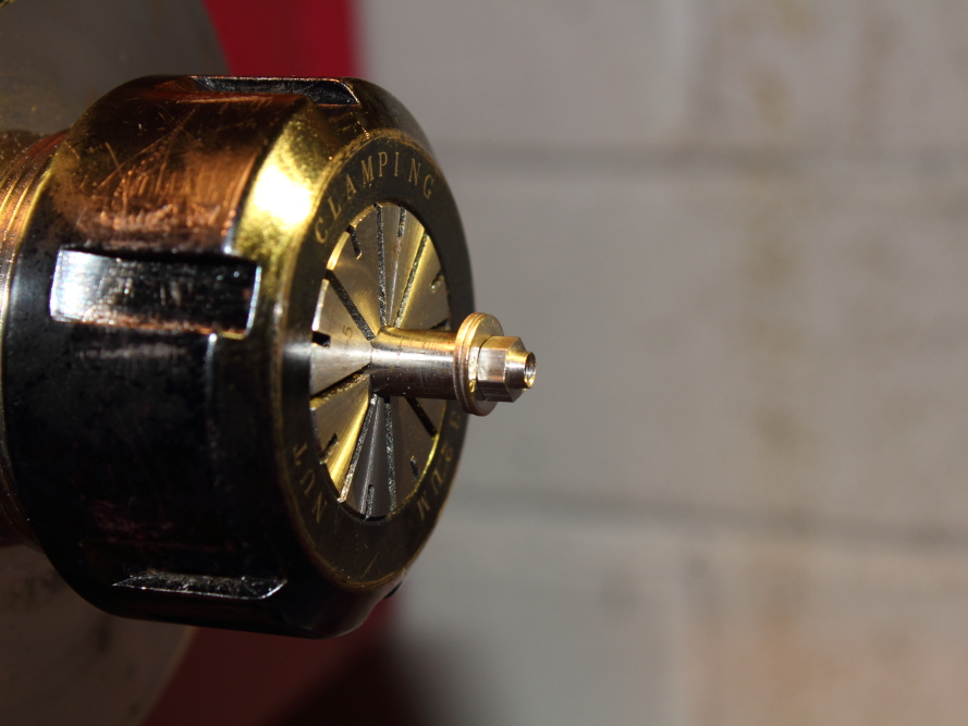
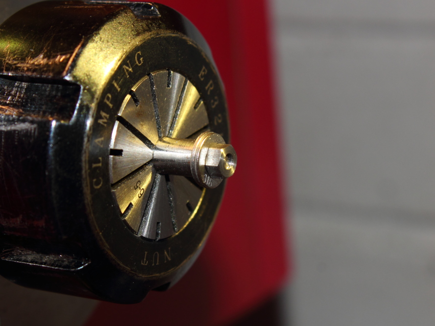
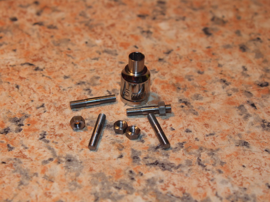
A length of 1/8” (3.18mm) BMS was chucked in the lathe (ER32 collet) about 25mm long and turned to 2.95mm diameter, an M3 die was used to thread 6mm long, then the rod was parted off 17mm long and this was repeated 3 more times.
I then inserted the threaded end of one stud into the collet to face and thread the other end.
I was worried about damage to the existing thread from the sharp edges inside the hardened collet and I was right to be worried, but going over that end with the die again (by hand) cleaned up the threads. I need something else to do this, but the ER collet is all I have for now.
A test fit to see if the threads were ok..
original.jpg

The remaining three studs got the same treatment and then a cap was test fitted.
original.jpg

Now it was time for the nuts.
I have some 5mm (0.2”) hex mild steel stock and I decided the nut should be about 2.5mm thick.
Modelling this in 3D (see an earlier post) the proportions were pleasing to my eye, so that is what I went with. I’m sure there is a standard out there but this looks fine to me.
The 4mm ER32 collet I was using for the studs has 6 point gripping, but when I put the 6mm collet into the holder I realised it had 8 point gripping, DOH!
Oh well, off with the collet chuck and on with the 3 jaw. The hex was faced and then the corners knocked off 30° with the side of a 60° single point threading insert. Drilled 15mm (~0.6”) deep with a 2.5mm drill then tapped M3. I couldn’t find my good M3 tap anywhere, I turned the workshop upside down and wasted a lot of time looking and ended up using a cheap and nasty looking M3 tap in frustration, but the threads actually cut quite nice and there was very little slop when test fit on a stud.
My parting tool reminded me I need some thinner ones, I’m wasting more material than I’m using on this small stuff.
original.jpg

original.jpg

original.jpg

To clean up the parted side of the nut I made a basic mandrel but ofcourse the die can’t cut right to the corner so a couple of washers were needed. With the nut threaded, the parting dag was taken care of with facing cuts and then the single point threading tool used again to knock the corners off.
original.jpg

original.jpg


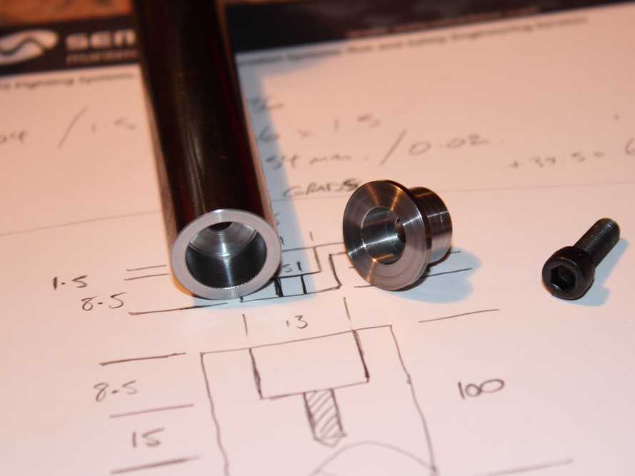
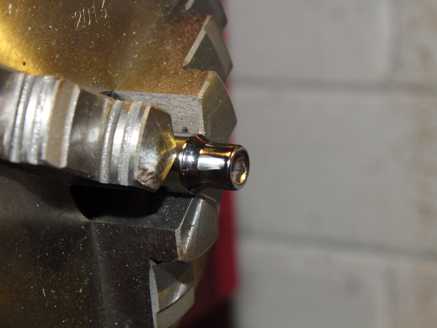
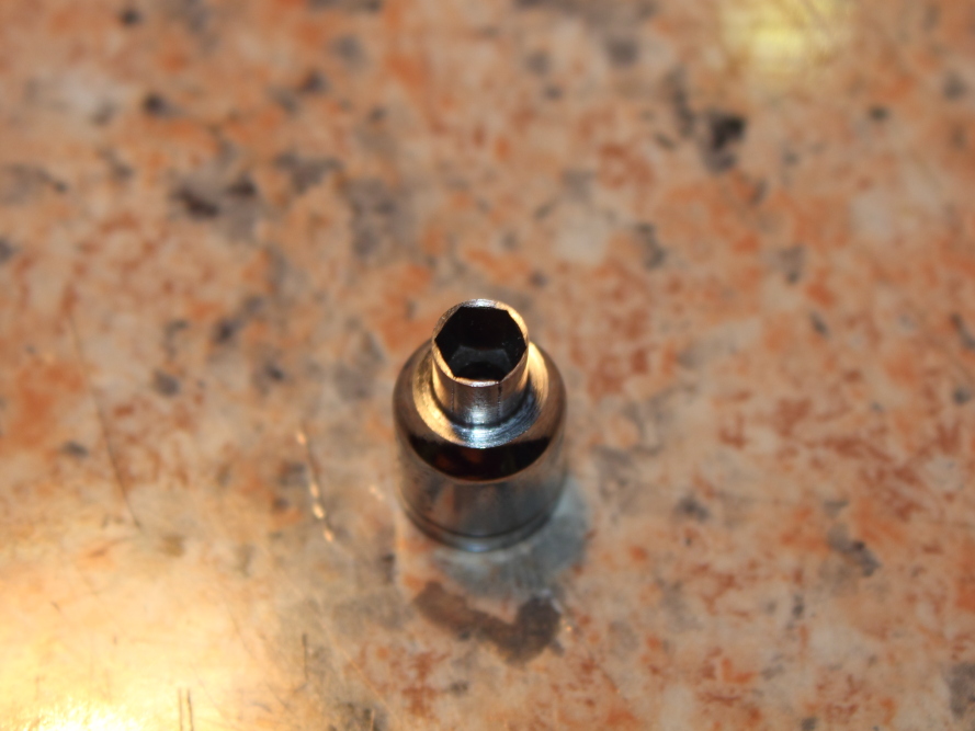
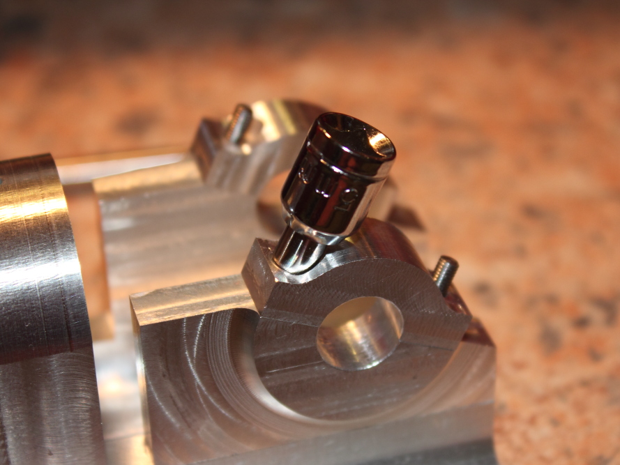
It was now time to try reducing a 5mm socket to fit the 7mm (~0.27”) counterbore.
The socket turned nicely, surprisingly, but in a moment of insanity I forgot to halve the cross slide travel and cut way too deep. It was the sound of interrupted cutting that reminded me of my error, and two of the corners broke through… oh well, the socket fits with plenty of clearance and it still works fine at the torque levels I’m using it, but I’ll find another socket to reduce at a later date.
original.jpg

original.jpg

original.jpg


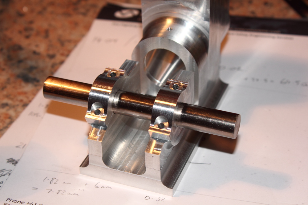
Now the socket, studs and nuts were done, it was time for another test fit.
Even though there were few parts made, Thursday felt productive and I’m quite happy with the result, but the studs do need shortening.
original.jpg

original.jpg


And that’s where Christmas took over.
I’m not sure where to go next, I was thinking the cylinder, piston and rings but I’ll need an ultra thin grooving tool and have decided is probably easier if I purchase from AR Warner and wait for delivery half way around the world.
Maybe I’ll continue at the back end here, line bore the bearing blocks/caps, turn the PB bushes, and move on to the crank.
 

Latest posts

Back
Top