Lesmo
Well-Known Member
- Joined
- Mar 1, 2011
- Messages
- 142
- Reaction score
- 16
First a thank you to Mike Freeman, Dave Piper (steamer) for sorting the problem I had when joining this great forum, back in March. Since then I have been trawling the site, soaking up info on how to get things done as I guess all novices do.
For my first project I decided, after reading both Brians and Kvoms builds that I would have a crack at this engine myself, even though my skill level is still on the bottom rung of the ladder. I recon if I can make it shiny enough, even if it doesnt work at least it will make a nice ornament and give me some experience in the process.
For the benefit of other novices I will describe my build (cock ups and all) in reasonable detail, hopefully, without the sending the reader, to sleep.
I had intended to complete the build before describing the journey but realized part way through, that posting as I went would probably be better as I, and any novice reading this, may get some useful advice and tips on better methods to have used in the production of the various bits.
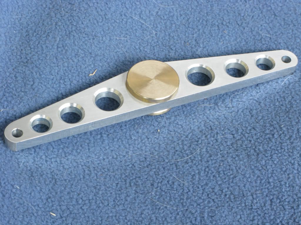
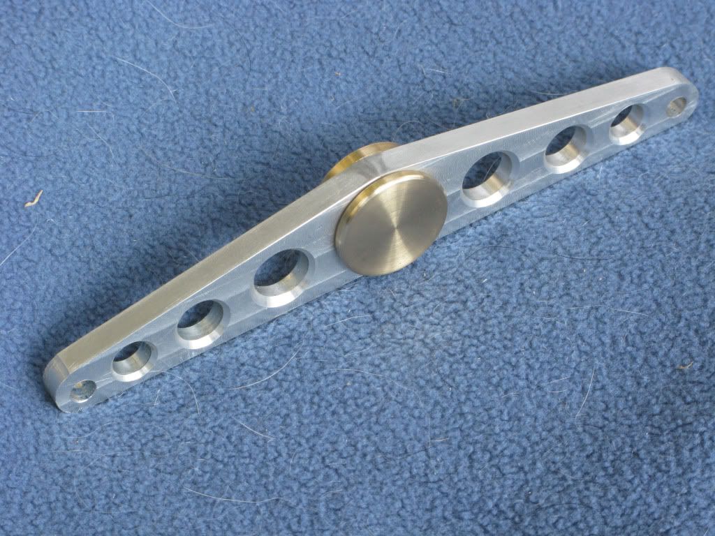
The story of my progress so far. I started with the flywheel and like Kvom I decided on a spoked flywheel, this being more difficult, would be a good test for my first play with a mill, but rather than using steel I would take the easier option of using ally.
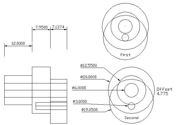
I tried without success to download Marvs flywheel prog, so I drew it out on my cad package, using node points at the centre of each hole to be drilled. During the process I thought that a little extra weight added around the rim would be a good idea so added a node mark above each spoke, for the 8mm holes, to take the brass weights.
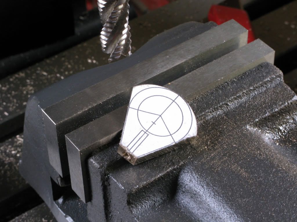
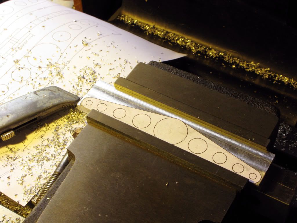
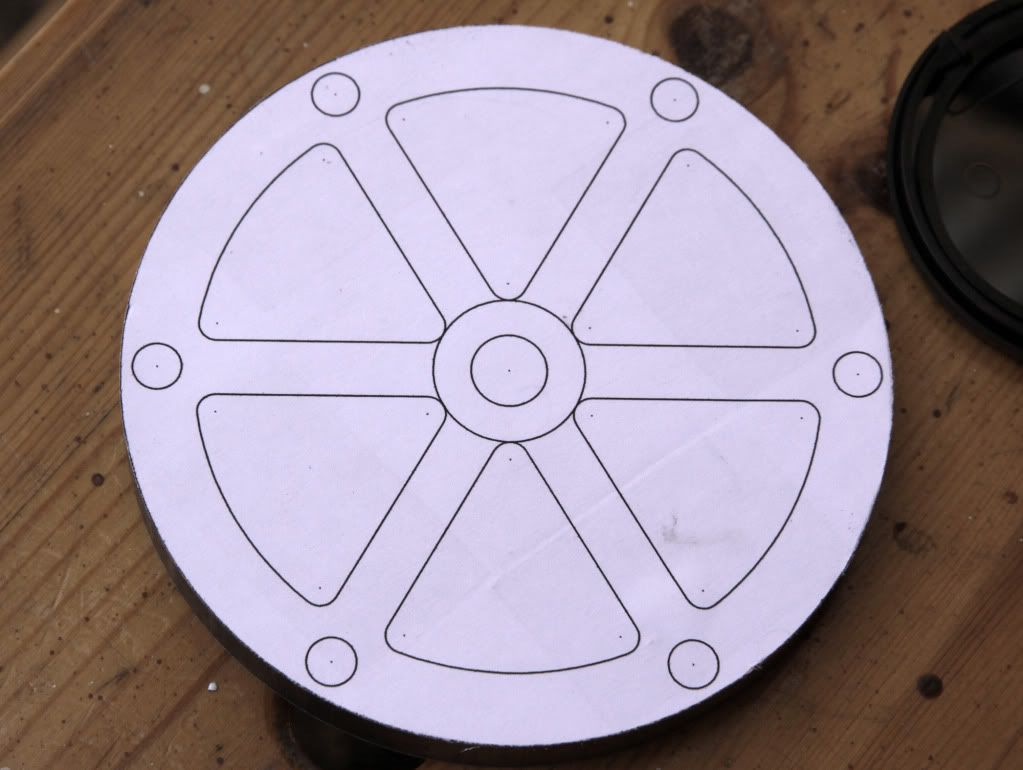
My marking out ability is crap, so I printed the drawing full scale so that I could, using double sided tape attach it to the faced ally blank using the centre drill hole for location, a process I continued for some other parts. I forgot to mention that all my parts have to be redrawn, measurements being converted directly from Imp to Metric except hole sizes which were to the nearest metric size.
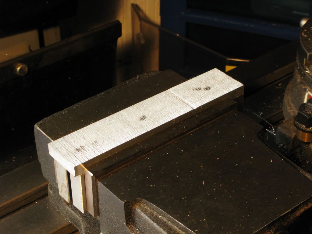
Sawn blank
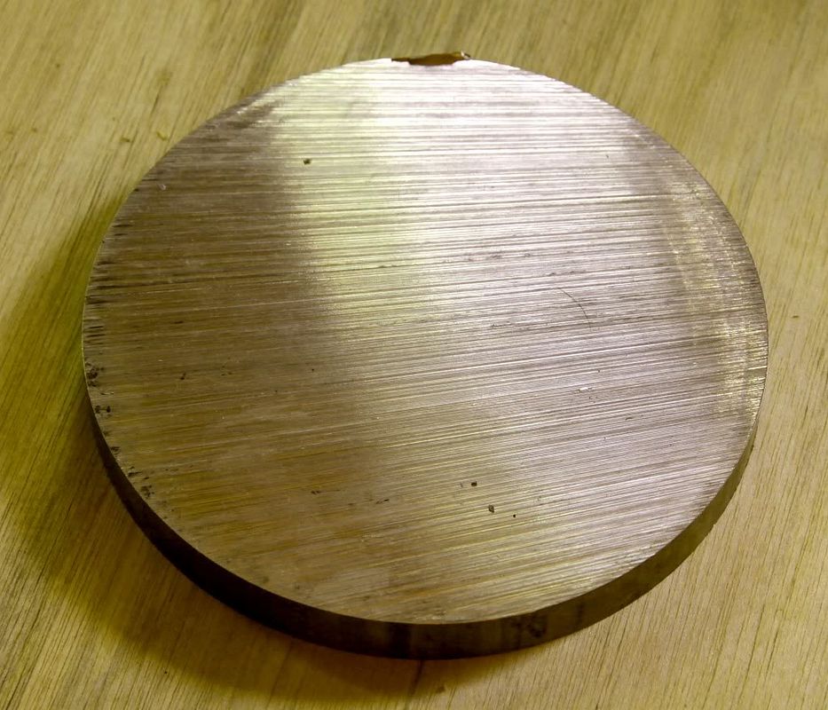
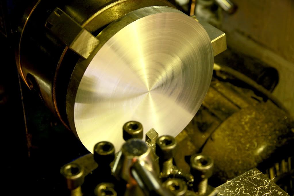
Both sides faced
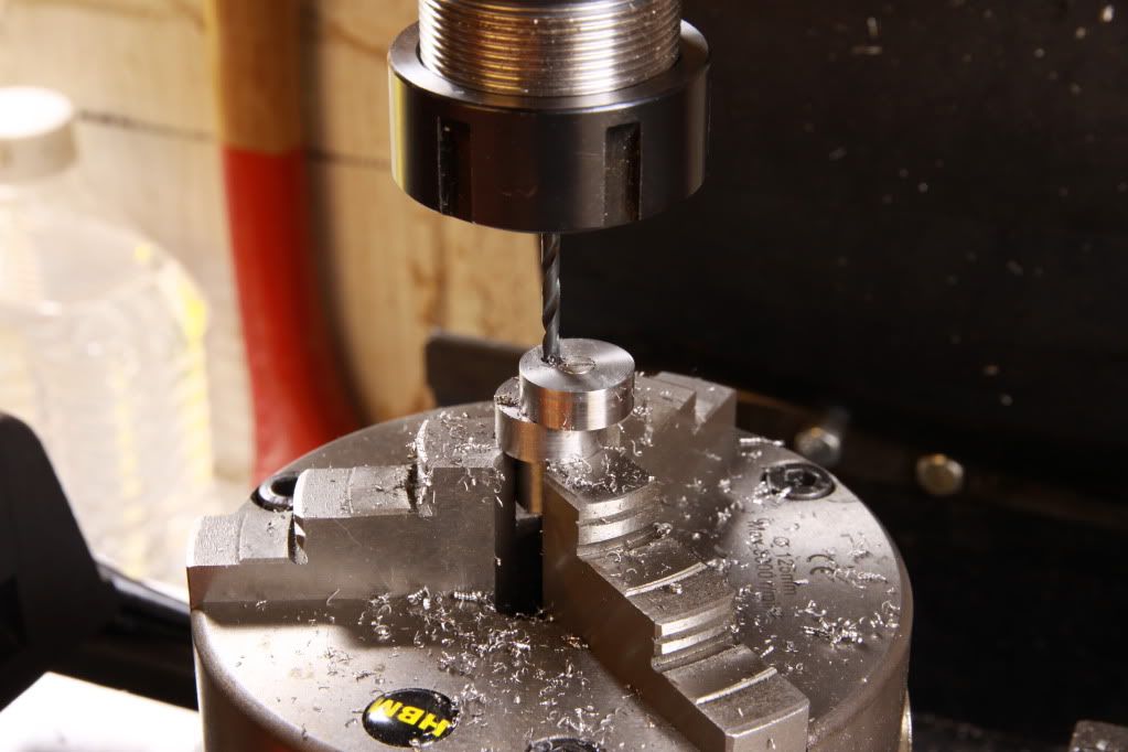
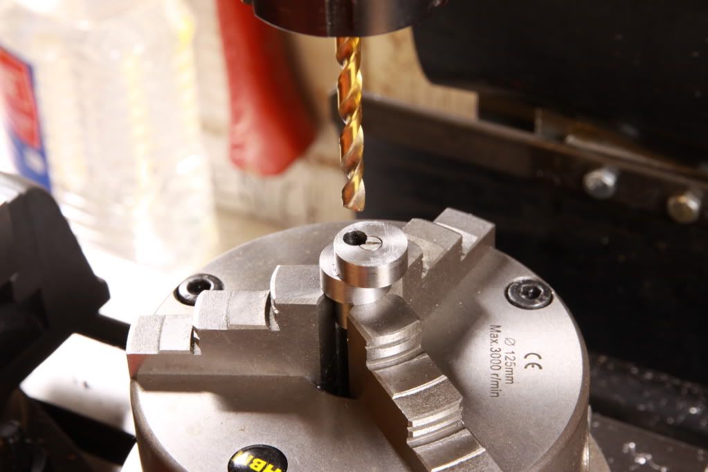
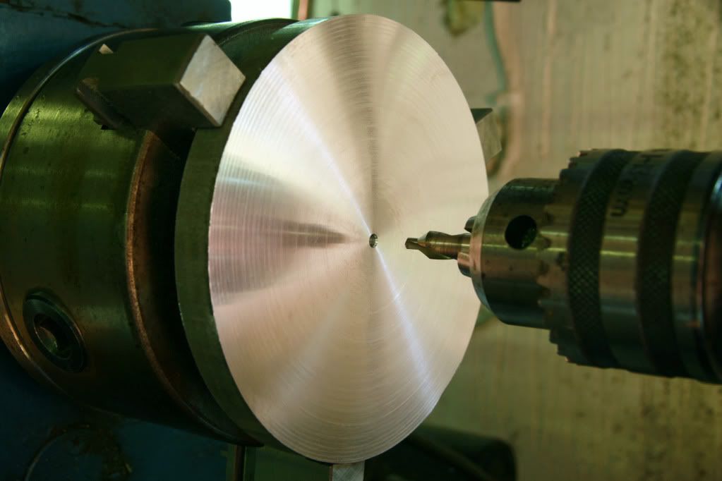
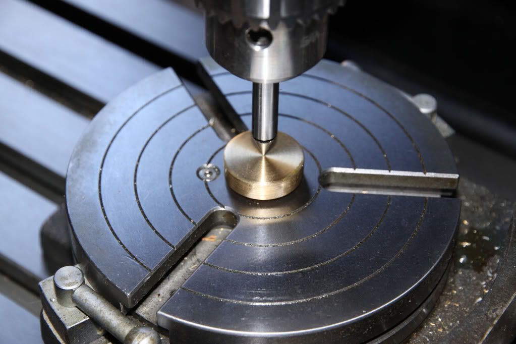
Centre drill blank as my zero point.
Blank with drawing attached
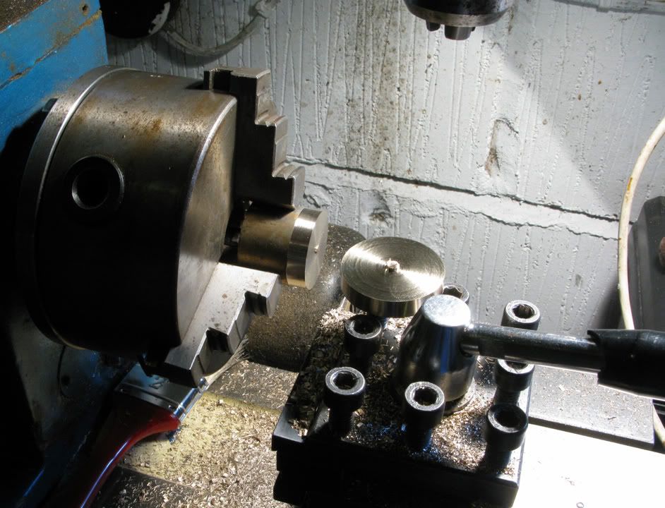
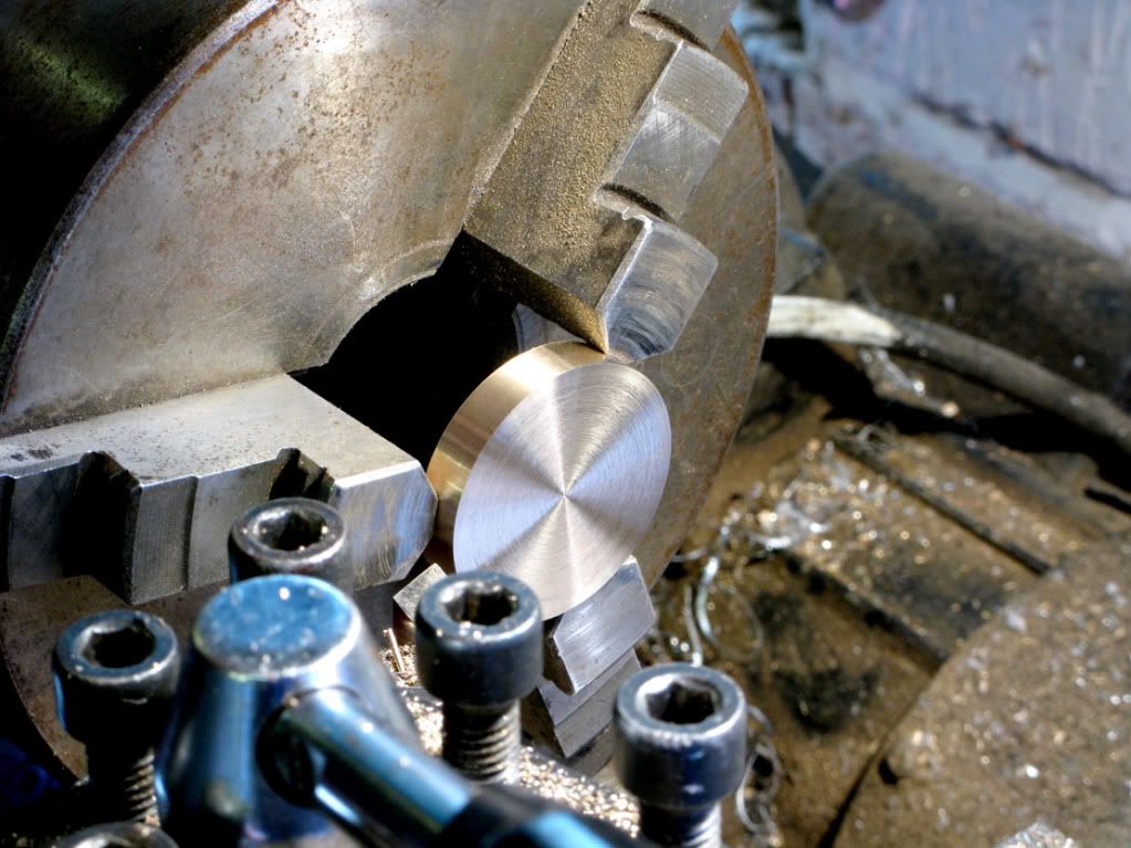
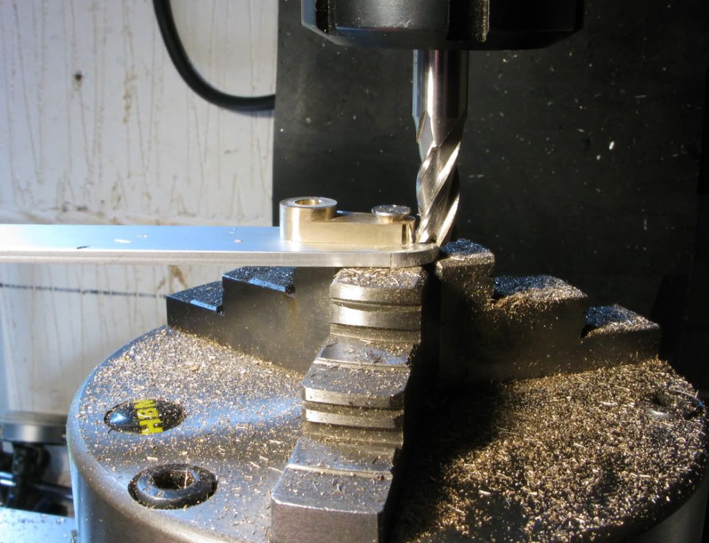
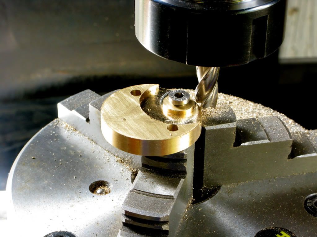
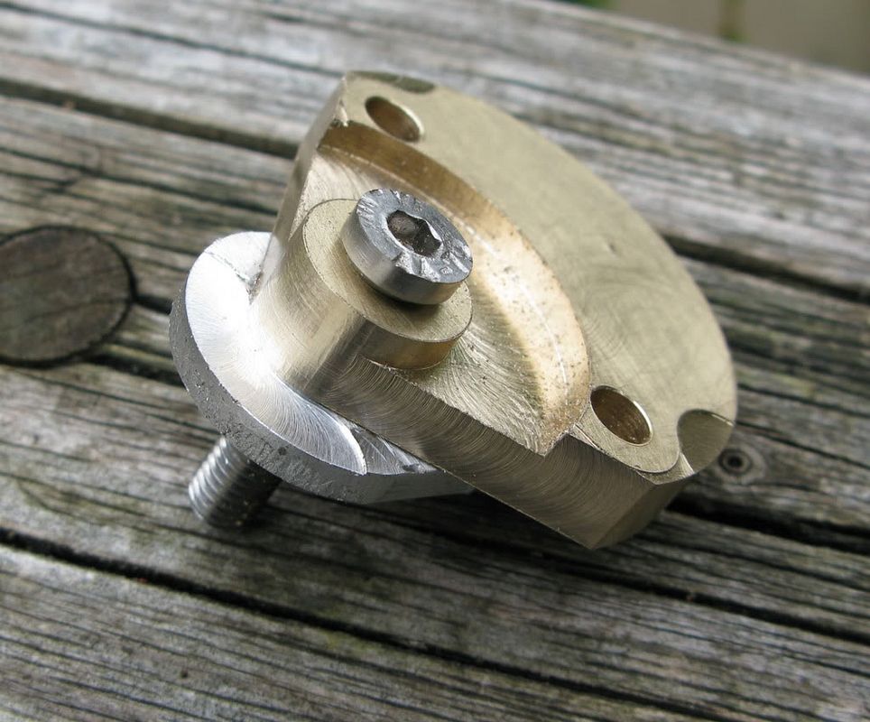
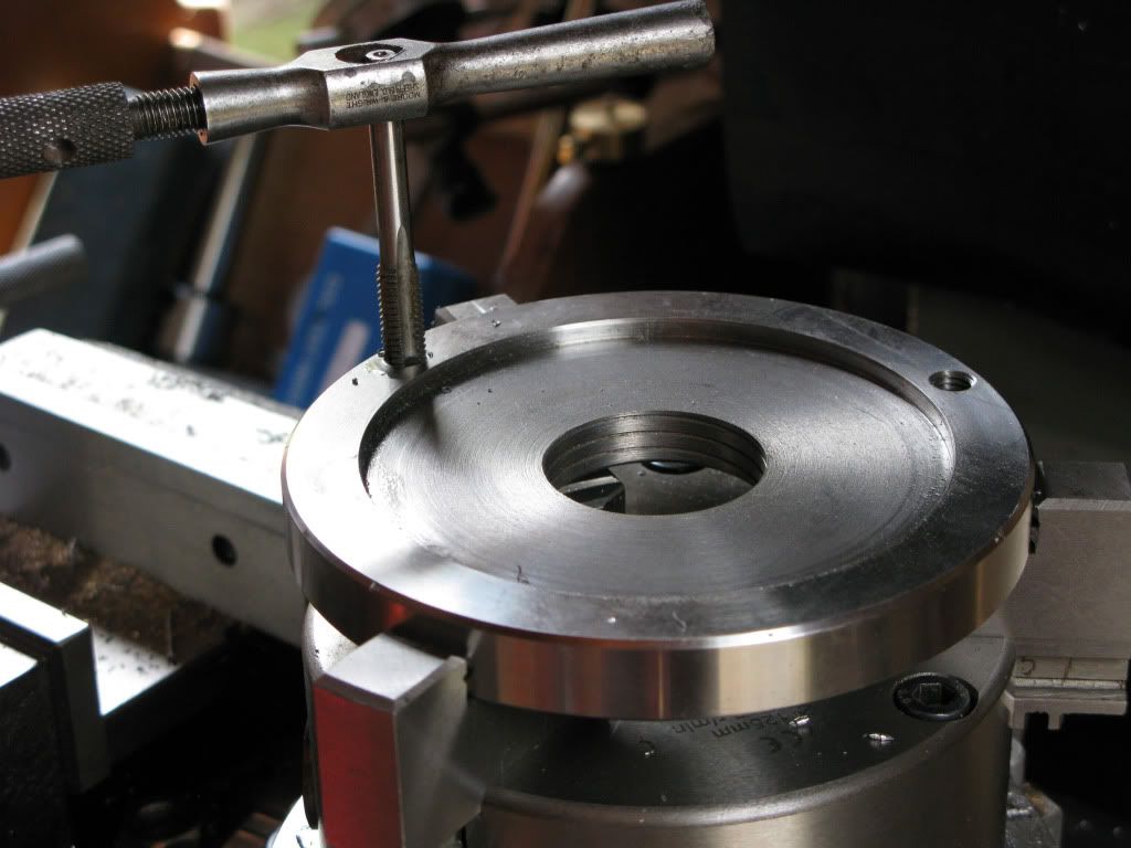
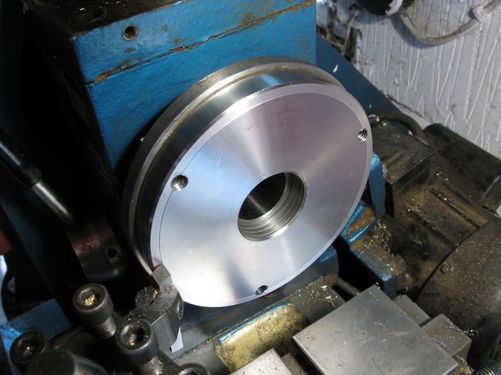
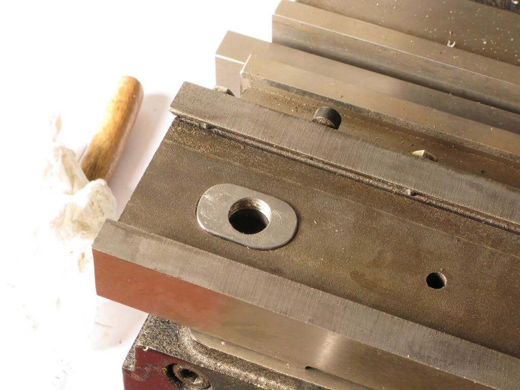
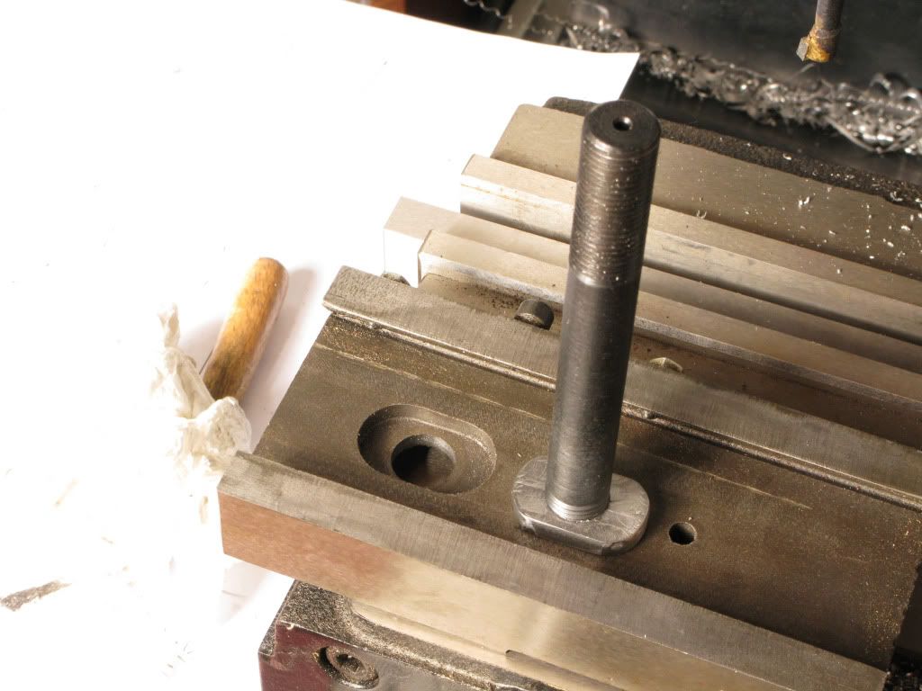
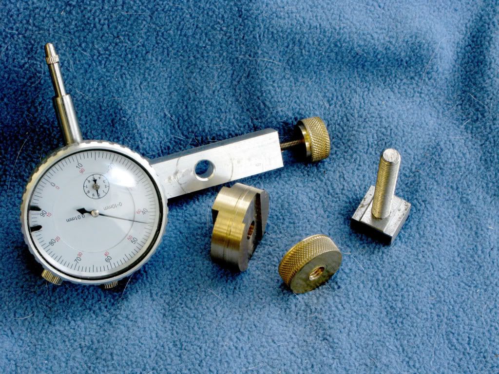
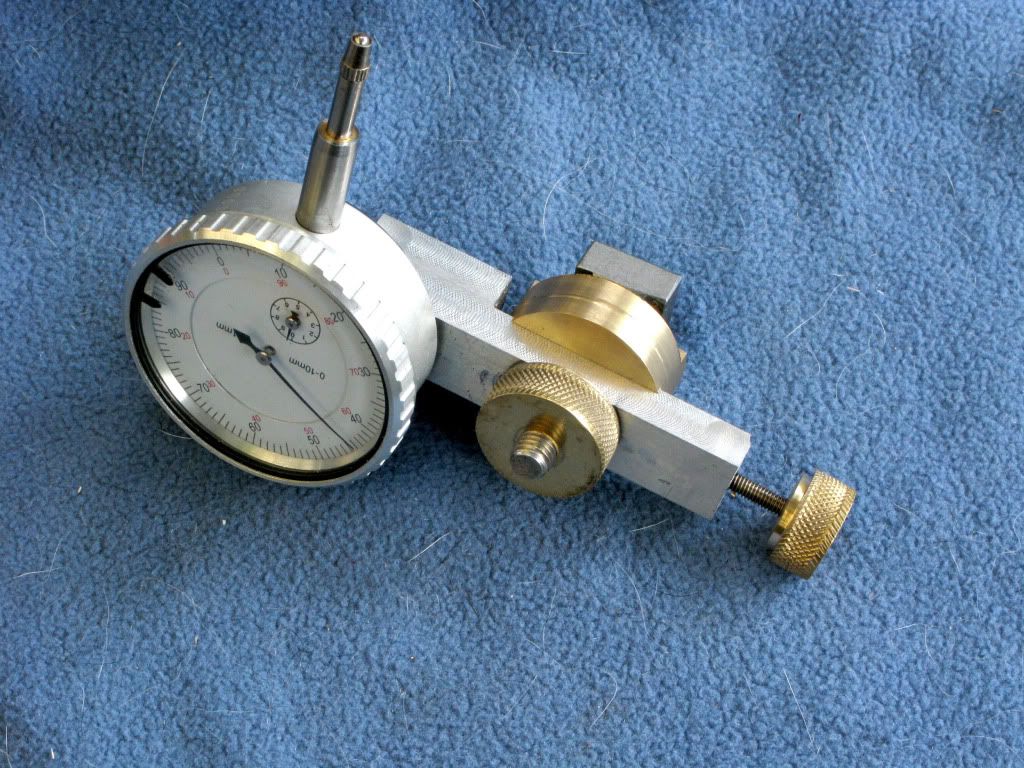
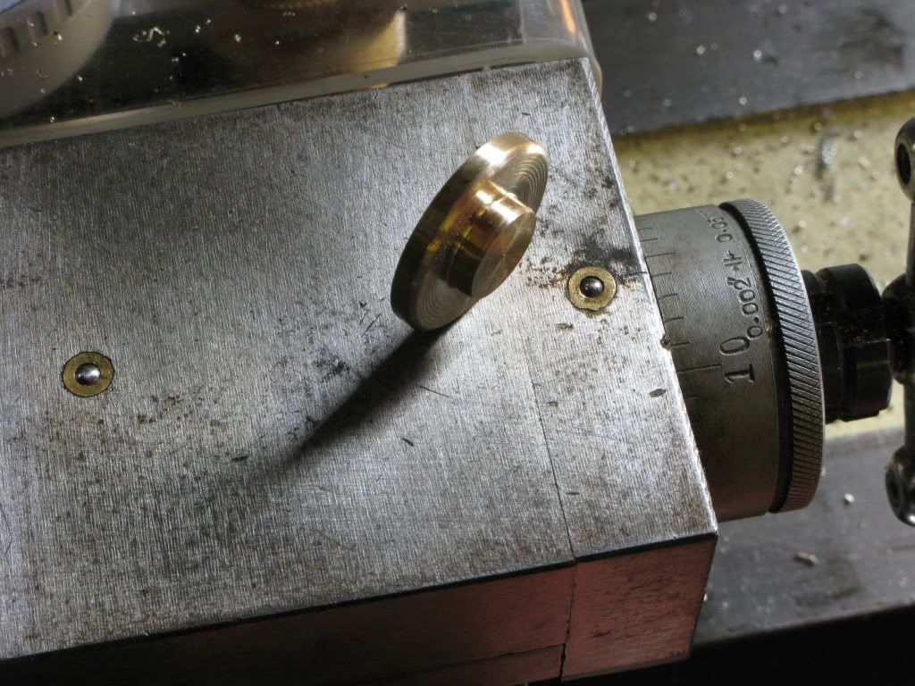
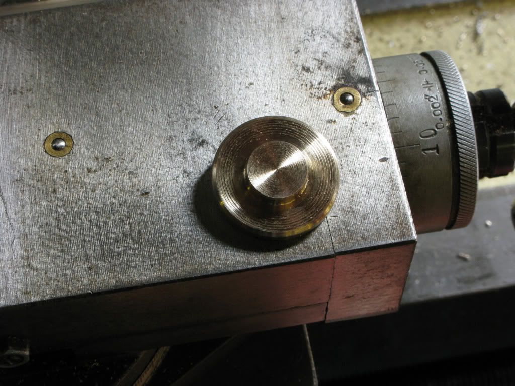
I now had to set up the rotab on the mill, and my 3jaw on the rotab, so to help get things close, I turned a piece of brass with a 2mt stub to fit into the rotab,
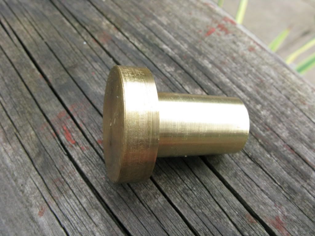
and a boss to fit the back of the chuck, plus a centre dimple for location.
[
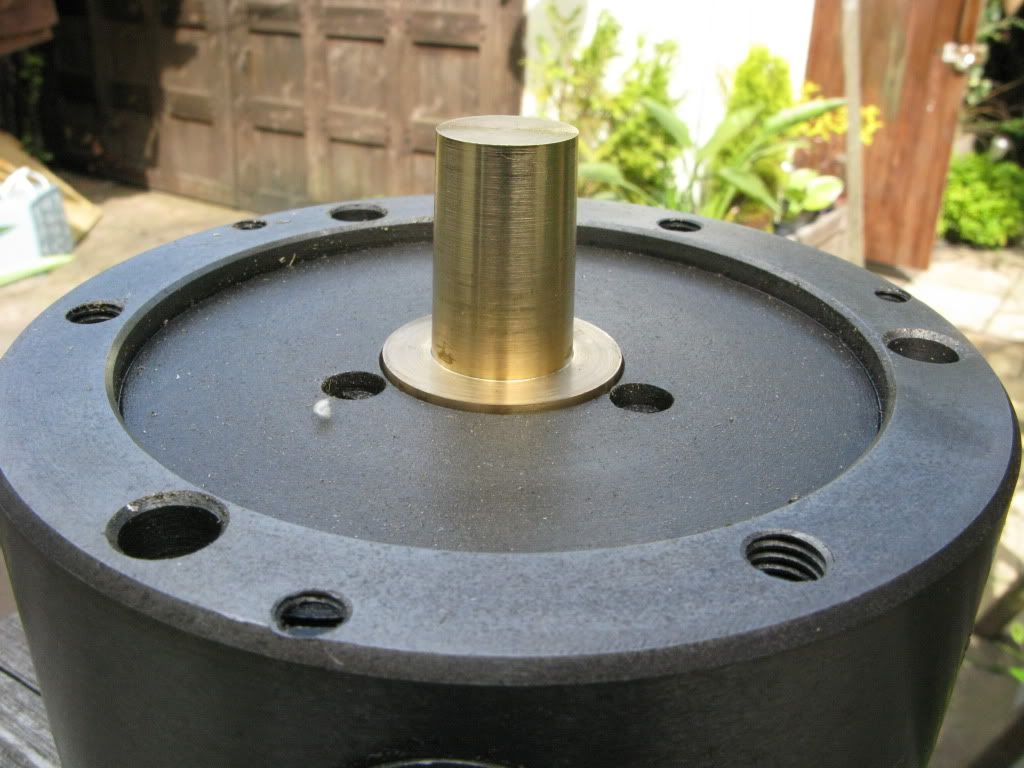
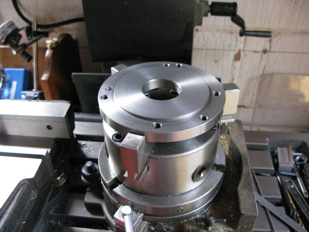
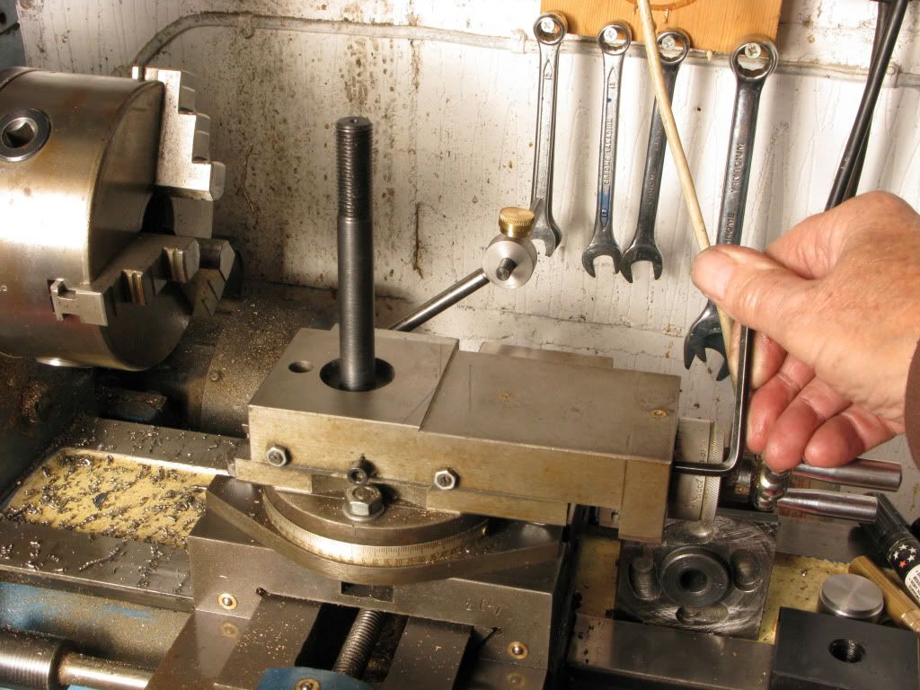
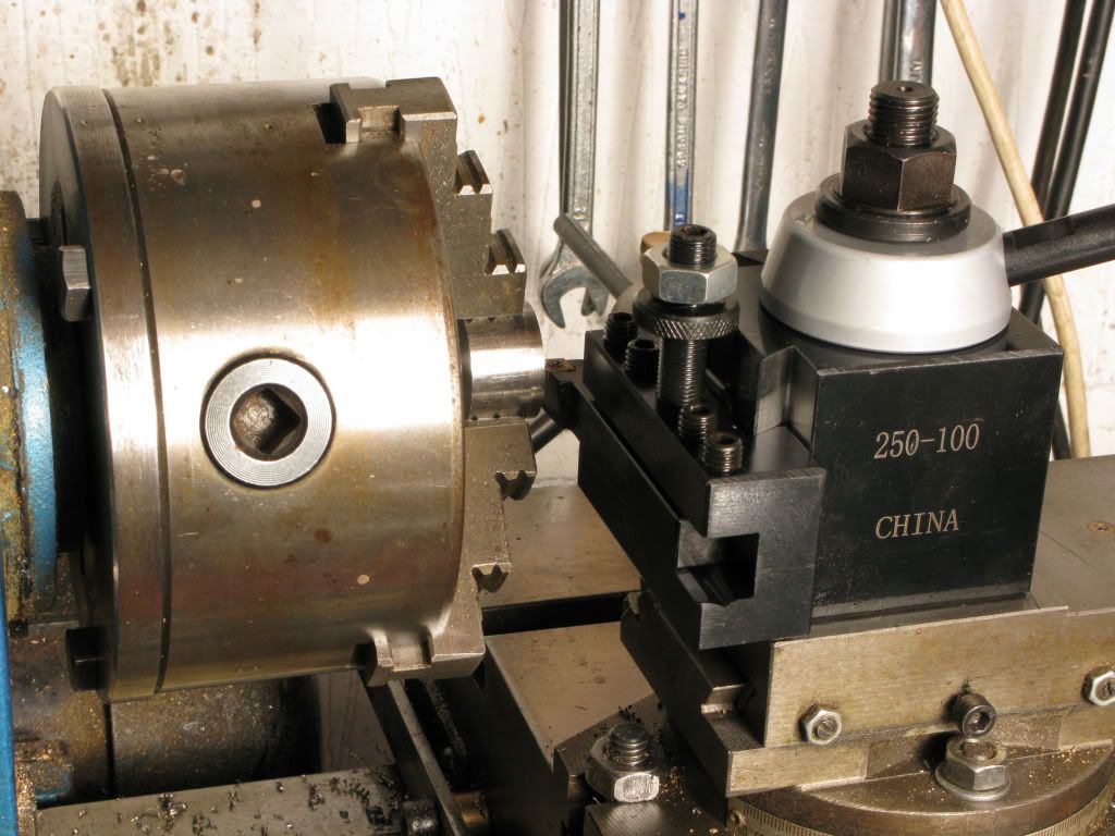
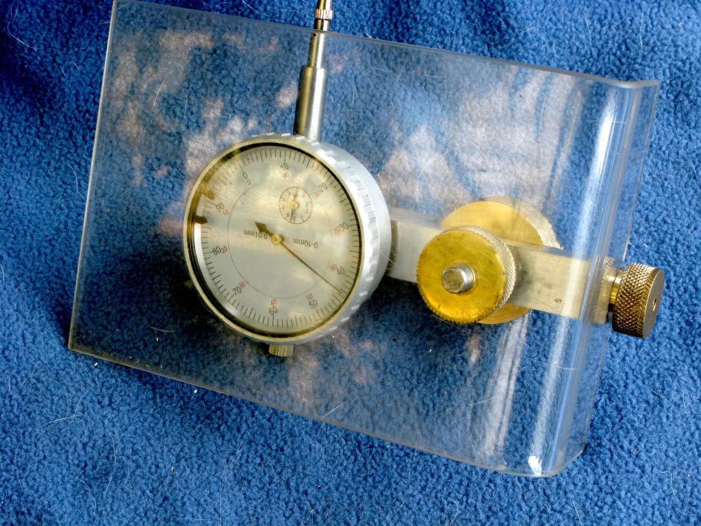
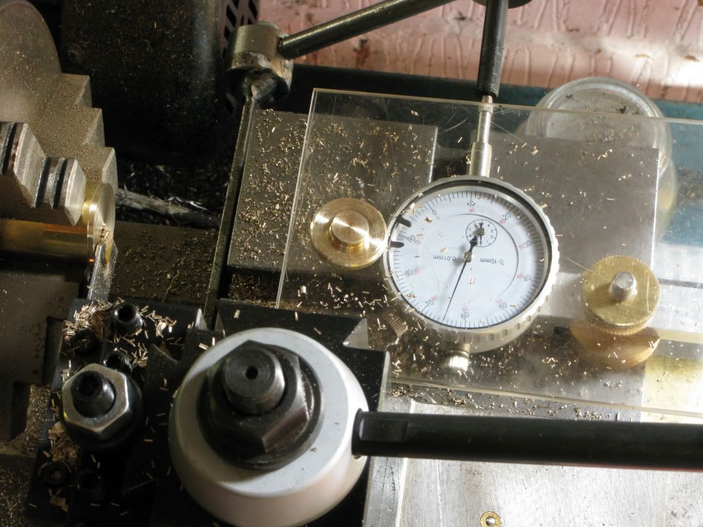
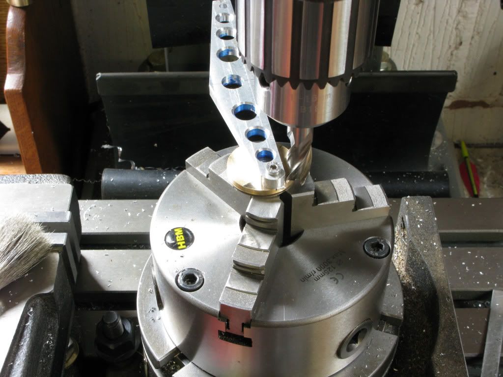
Using the brass stub I set the rotab on centre then dialed it in and locked it down,
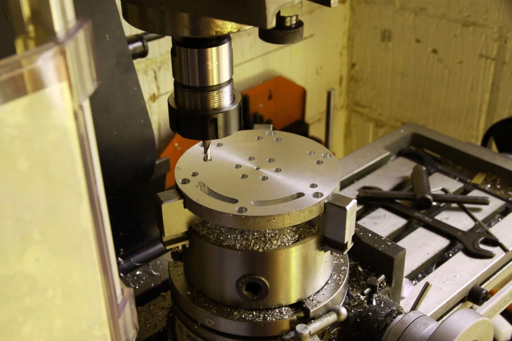
fitted the chuck and dialed that in, finally securing the blank in the chuck jaws, using three 3mm drills as parallels to give clearance from the jaws . Then I checked the centre node using a centre finder. (a better method would have been to locate the drawing last using the centre node) even better would be, improve my marking out ability.
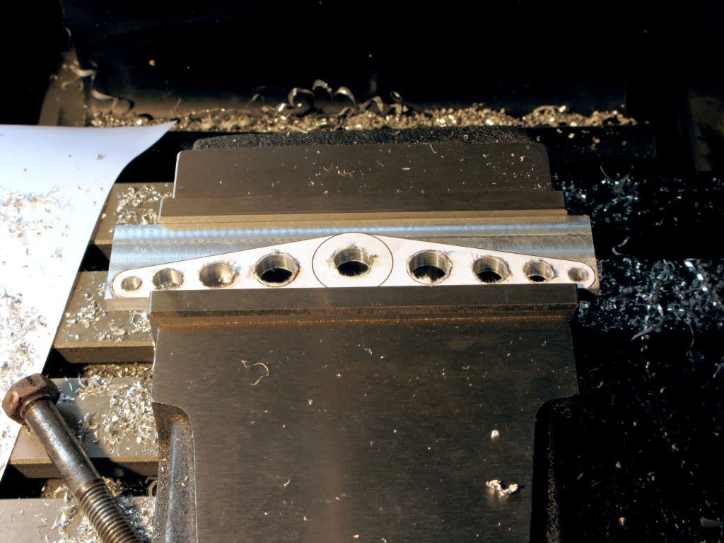
Using a 10x magnifier and centre finder I lined up the first hole of each ring, after getting them aligned across with the X axis then drilled each of the six 6/8mm holes turning the rotab dial the required number of turns between each.
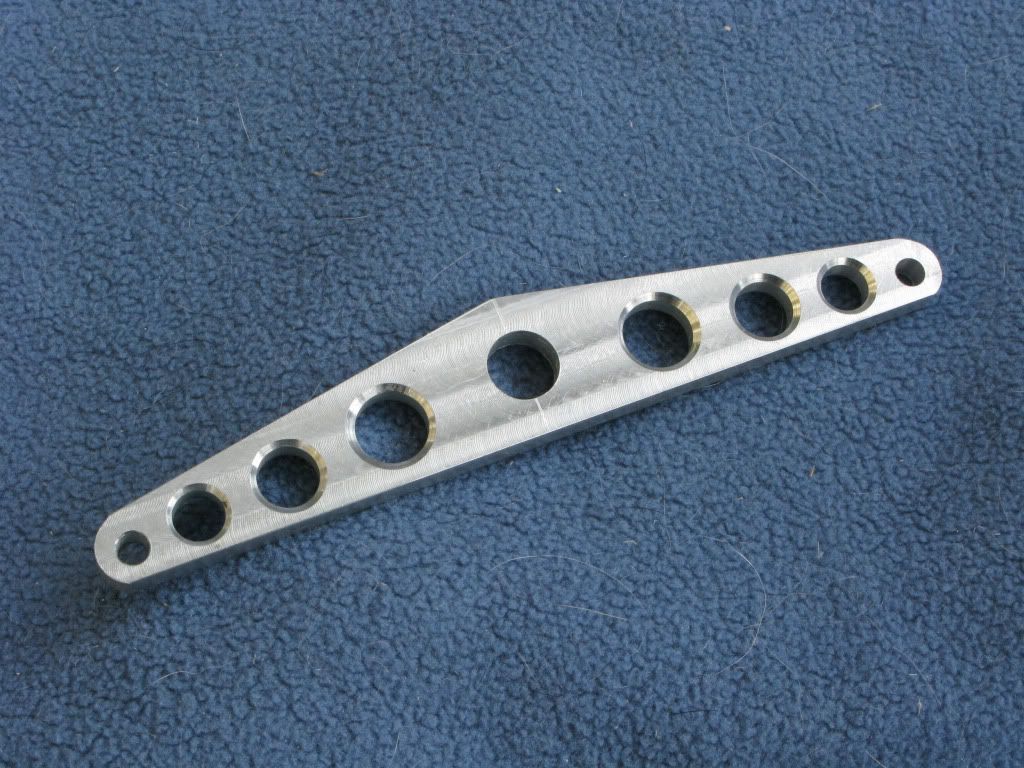
I followed the same procedure to trepan out the triangles, completing one slot of each before continuing to the next.
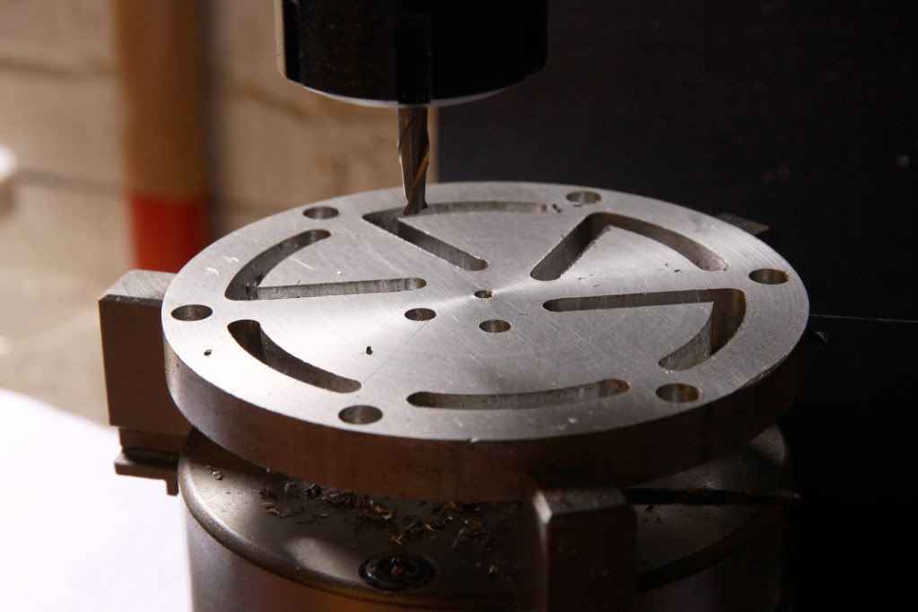
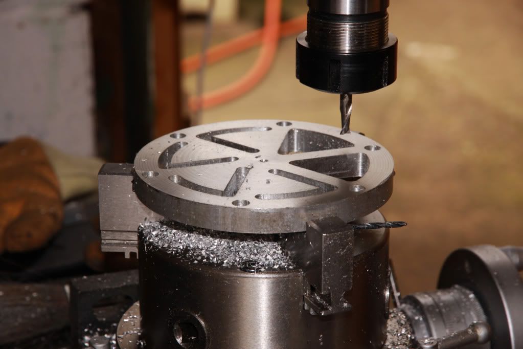
I milled in both directions and all went well until at the start of two outer curves I turned the rotab dial the wrong way and screwed them up. I completed the trepanning ant the cock ups were so visible I gave up for the day.
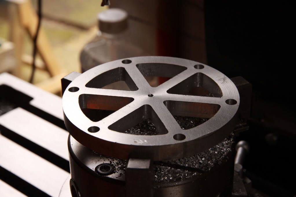
Later that evening I thought of a way to rescue the piece from the scrap bin. Someone with experience would have recognized this immediately, I simply had
to re-drill all the holes from 6mm to 8mm. I drew it out first, to see what effect it would have and it looked just fine, so the following day I using an 8mm end-mill I re-drilled the two screw ups first, to see if 8mm was enough to correct the faults and it was, so I drilled the rest and joined up the dots.
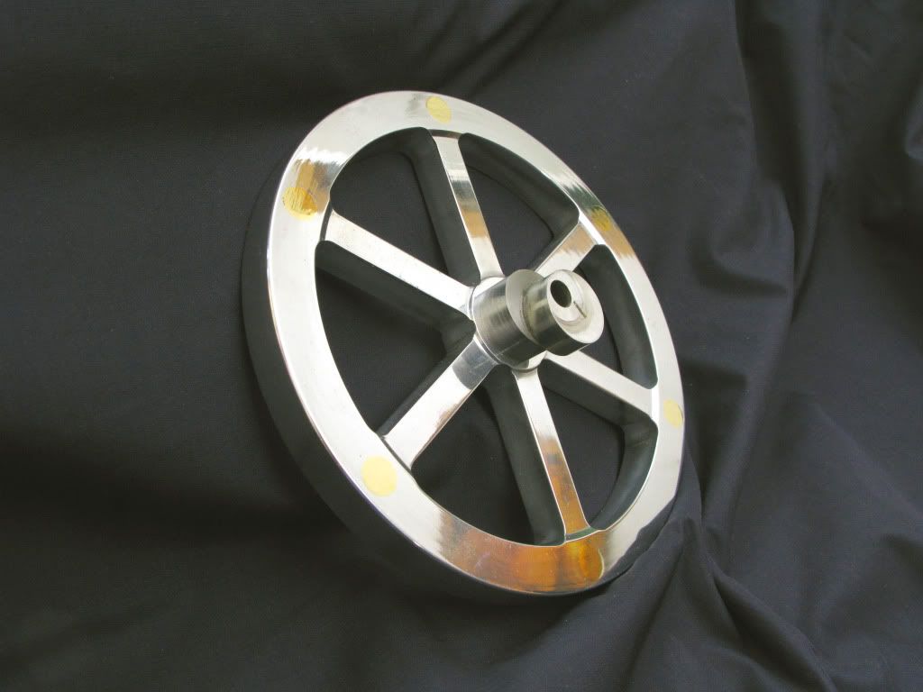
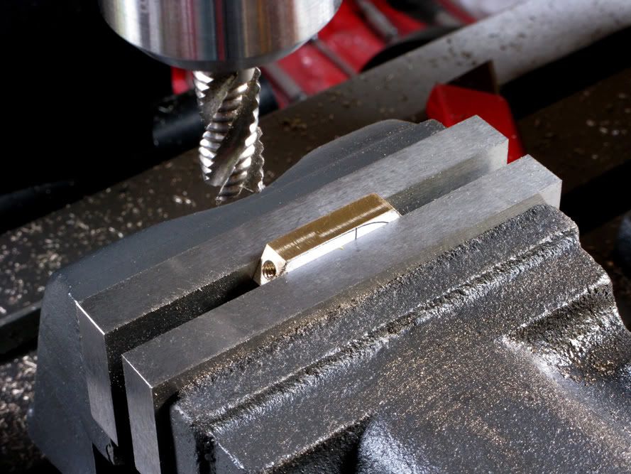
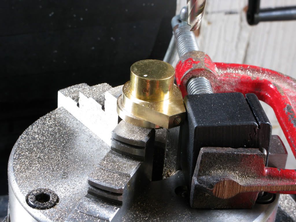
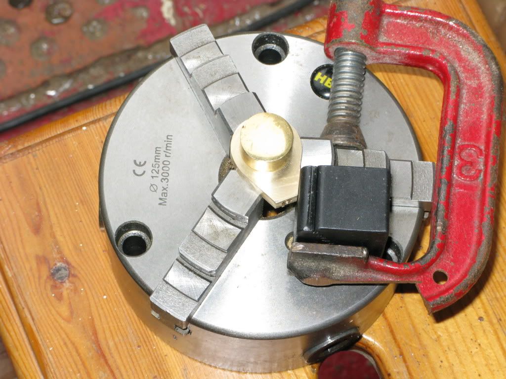
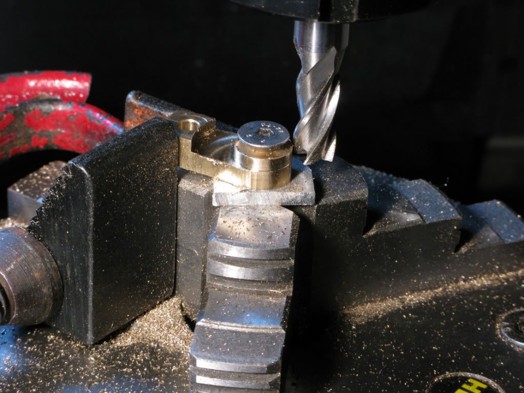
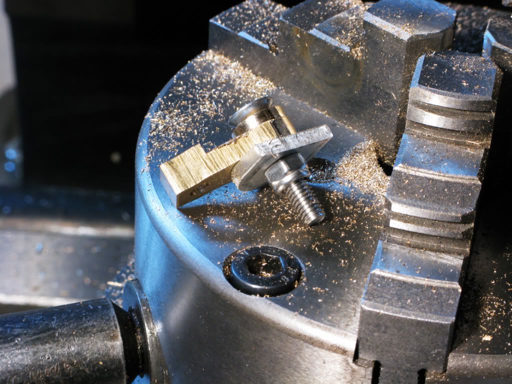
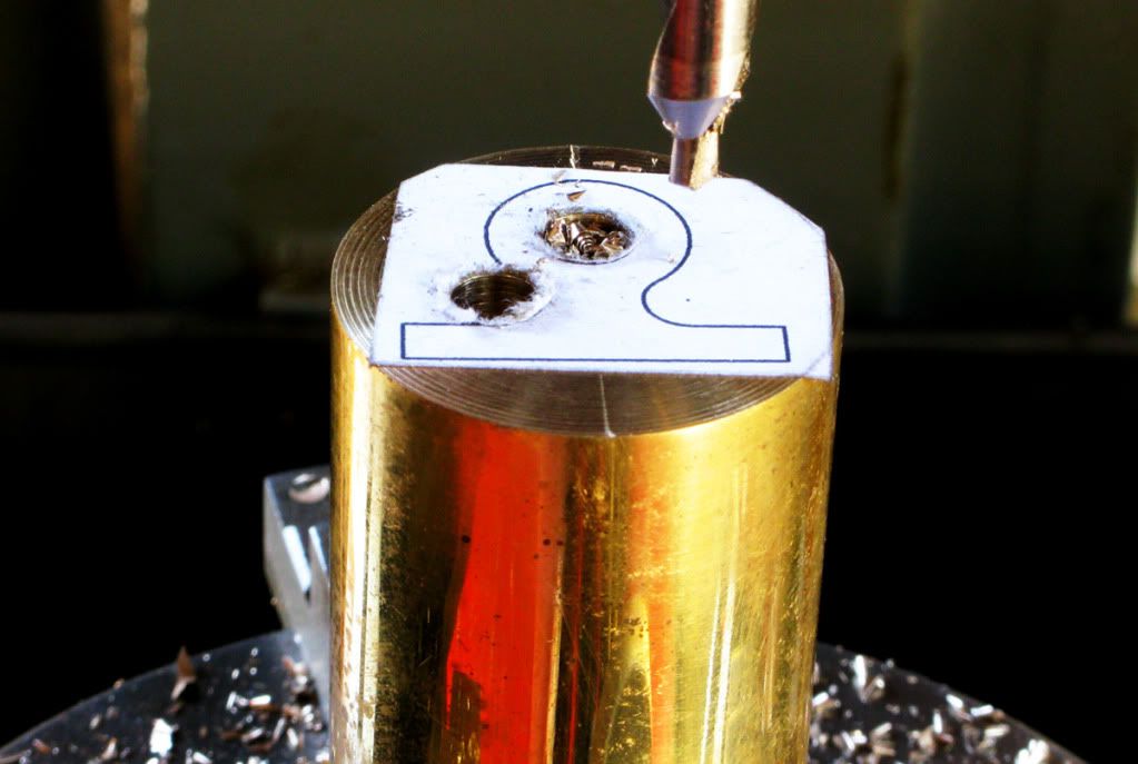
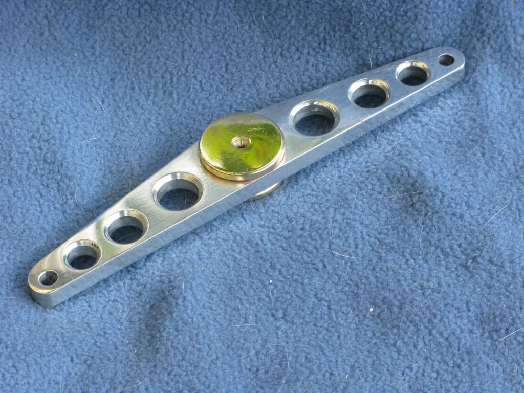
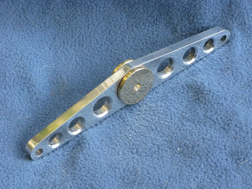
The next step was to make and fit the brass dowels
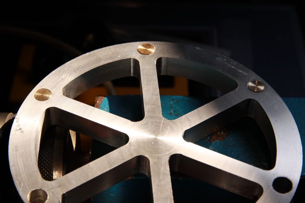
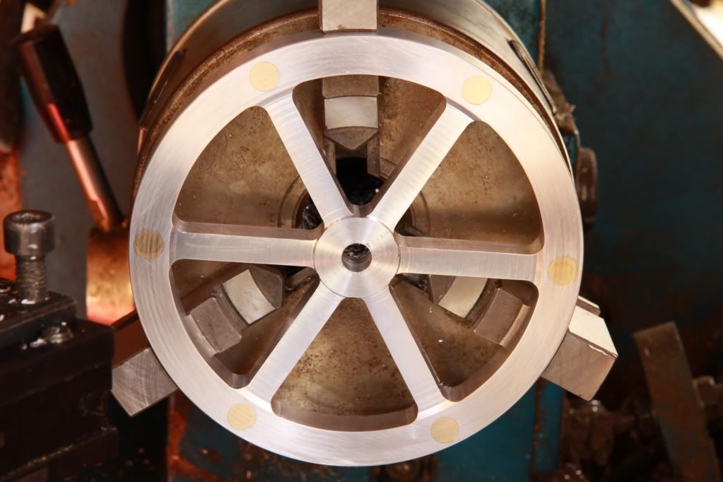
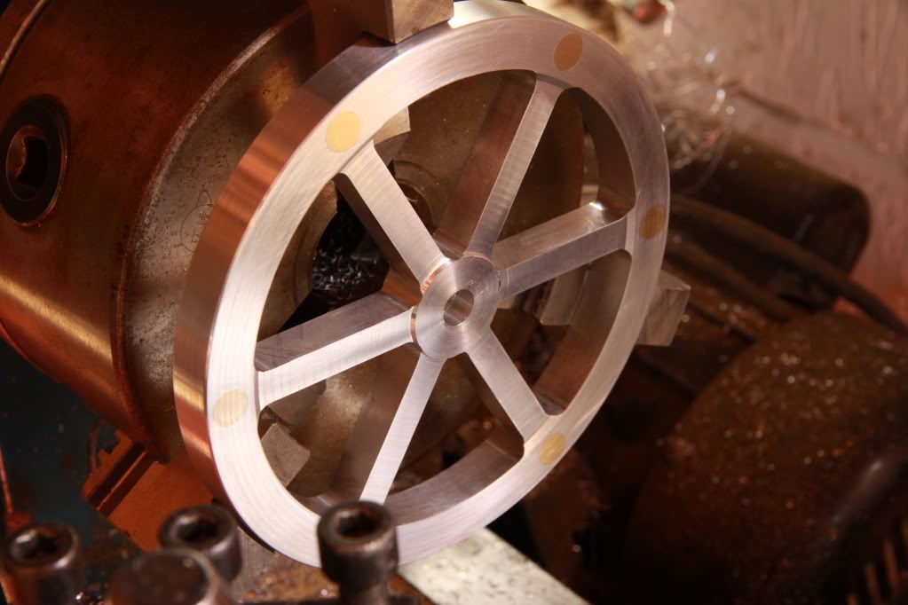


") I like the contrast of the brass dots on the flywheel too!!
I like the contrast of the brass dots on the flywheel too!!