1/4 Scale Benz Engine (Inch) Model

Home Model Engine Machinist Forum

Help Support Home Model Engine Machinist Forum:

This site may earn a commission from merchant affiliate links, including eBay, Amazon, and others.
I'd also be interested in seeing this one develop. It's an engine that I have liked the look of for a while but buying from Torsen at TS is a bit of a pain as he only accepts bank transfer and you have to also pay his bank costs for non Euro payments as well as my bank's which makes it expensive.

Craig, you should be able to open Solidworks part files with Alibre depending on what version you have though they will just open as a single part not all the sketches etc that were used to create each part but can be modified from that or a drawing produced.

I take it you have seen Tom's 1:1 scale build of the engine and wagon that he did on here a number of years ago
 
Craig & Jasonb,

Appreciate the encouragement, it is enough to boost my enthusiasm for getting back to this project. Attached is just the head as completely done. Naturally since I have not fabricated one yet, I am guessing at what the fillet radius would be, I'm thinking of brazing as it tends to leave a larger fillet, Silver Solder would be stronger and I'll do that for the inner part like the 'D' shape in the head (Will be out of sight and with the higher temp. required won't be affected by the subsequent brazing of the Mtg, & Exhaust Bosses.

I had a good friend who came to my shop 1/week to work on his engine, he passed last Sunday :confused: , and I am trying to sort out how to rearrange my thought, time and projects, this project may well be just what I need to handle the sense of grief.

Also I've attached a couple of doc's from the source I used to get the proportions right, one is from the set of drawings that were or are still sold in Europe, the other is from an HMEM post. That and some deductive measuring, calculator work and head scratching😏 brought me to where I am.

Craig, nice looking work on the stuff in your ID photo, looks as if we are about the same vintage, I was born in 1939, you?
 

Attachments

  • Note on Head Const.pdf
    165.4 KB
  • Benz - Cilinder & Heads.jpg
    Benz - Cilinder & Heads.jpg
    264.6 KB
  • Benz LH Side view.jpg
    Benz LH Side view.jpg
    122.1 KB
Hi Ken and Jason…(Jason’s is a former acquaintance from MEM)

Looks like Jason and I have your interest back. Sorry to hear about your friend; I lost one of my mentor’s last year. I have a few of his tools to remember him by so he’s still with me when I’m in the shop. Regarding age; I don’t like to publish it… to many crazies out there trying to steal your identity. I’ll just say that you have me beat by a decade, give or take.


Thanks for the information you've provided. I’m assuming the one photo showing the cylinder castings isn’t yours since you’ve stated you’re going with weldments. The head you have designed looks pretty good; probably a bit more detail than I’d contemplate.

I poked around here on HMEM and found the thread to which you refer… (another Karl Benz 1886 Engine and Motor Wagon) that appears to have a lot of the detail for which I was searching. Don’t know why my initial search didn’t find it. I have lots of reading and planning to do before I might contemplate a design and build.


I did find a 5 curved spoke flywheel that could be cut down to possibly resemble the flywheel on the motor wagon engine from Martin Models in Oregon (5½" Flywheel 5-Spoke Curved) I haven’t looked into seeing what scale that might work out to.

I’m still heavily involved with my current build and don’t want to distract my thinking on another project just quite yet… probably around mid summer I can start thinking seriously about a possible motor wagon build. Meanwhile, if you continue with your build I’ll be watching, commenting, and maybe participating if you ask. Craig
 
I could not open the head notes yesterday but can now. That is going to be quite a small item to weld and grind down all the fillets after and even if brazed quite a bit of grinding but you are probably a better welder than me!

My thoughts on a part like that would be to turn the head including the flange, counter bore for some rods here each of the head studs go and then make a block for the exhaust with a concave cut and silver solder it all together. I can get a reasonable fillet with silver solder and something like JB Weld can be used to add a bigger one if needed.

Similar head construction

DSC00964_zpsbk729qgp.jpg


DSC00966_zps2etbjukr.jpg


The Cylinder and "Fork" both look like a similar turning first would be the way to go then solder on the bits to the cylinder. Fork again turned and cut away teh end to form the two prongs and add location slots down the sides. Solder on the two webs down the sides and two blocks for the bearings at the end.

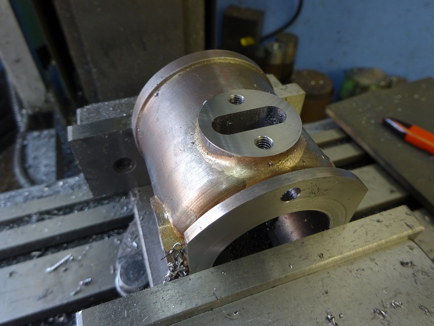
A cylinder that was turned and had the bosses soldered on

DSC00979_zpsfwnwqkaf.jpg
Great ideas and nice job Jason. I did simular to what you did on the Witte model I built a while back, except that I attached the cylinder boss (an igniter boss in my case) with small screws and sealed it with JB weld. Made the fillets with JB weld too.
 
Craig & Jason,

OK did not take a lot of urging to reignite my interest, here is this morning's Solidworks effort, the attached is what I see as the logical approach to making the head from solid material, it would all be steel the colors are merely for component identification. I'll of course create drawings for each part, then for the machining of the weldment. The tapered pins are just that, standard taper pins available in most good hardware stores.

You had guessed correctly on the source of the metric drawings, that post was what interested me in the 1st place.

Thanks for the pointer for Martin Flywheel castings, now to decide size.
 

Attachments

  • Head-Weldment.JPG
    Head-Weldment.JPG
    48.8 KB
I could not open the head notes yesterday but can now. That is going to be quite a small item to weld and grind down all the fillets after and even if brazed quite a bit of grinding but you are probably a better welder than me!

My thoughts on a part like that would be to turn the head including the flange, counter bore for some rods here each of the head studs go and then make a block for the exhaust with a concave cut and silver solder it all together. I can get a reasonable fillet with silver solder and something like JB Weld can be used to add a bigger one if needed.

Similar head construction

DSC00964_zpsbk729qgp.jpg


DSC00966_zps2etbjukr.jpg


The Cylinder and "Fork" both look like a similar turning first would be the way to go then solder on the bits to the cylinder. Fork again turned and cut away teh end to form the two prongs and add location slots down the sides. Solder on the two webs down the sides and two blocks for the bearings at the end.

A cylinder that was turned and had the bosses soldered on

DSC00979_zpsfwnwqkaf.jpg
Definitely nice looking job, as mentioned a little JB Weld, sanding & painting it will look great. Is that silver solder or braze. my silver soldering does not leave that much of a fillet.
 
Hi Ken and Jason…(Jason’s is a former acquaintance from MEM)

Looks like Jason and I have your interest back. Sorry to hear about your friend; I lost one of my mentor’s last year. I have a few of his tools to remember him by so he’s still with me when I’m in the shop. Regarding age; I don’t like to publish it… to many crazies out there trying to steal your identity. I’ll just say that you have me beat by a decade, give or take.


Thanks for the information you've provided. I’m assuming the one photo showing the cylinder castings isn’t yours since you’ve stated you’re going with weldments. The head you have designed looks pretty good; probably a bit more detail than I’d contemplate.

I poked around here on HMEM and found the thread to which you refer… (another Karl Benz 1886 Engine and Motor Wagon) that appears to have a lot of the detail for which I was searching. Don’t know why my initial search didn’t find it. I have lots of reading and planning to do before I might contemplate a design and build.


I did find a 5 curved spoke flywheel that could be cut down to possibly resemble the flywheel on the motor wagon engine from Martin Models in Oregon (5½" Flywheel 5-Spoke Curved) I haven’t looked into seeing what scale that might work out to.

I’m still heavily involved with my current build and don’t want to distract my thinking on another project just quite yet… probably around mid summer I can start thinking seriously about a possible motor wagon build. Meanwhile, if you continue with your build I’ll be watching, commenting, and maybe participating if you ask. Craig
Craig, looked at the Martin Casting site, and the 7" curved spoke flywheel would (IMHO) the best choice for this 1/4 scale, that is what I,m going to go with.
 
It's silver solder about 620deg C melting point. I don't have oxy so can't really get the heat for brazing though I do have an old carbon arc "torch" it seldom gets used.
 
Spent some time noodling out how to approach this engine as a weldment vs. a casting.

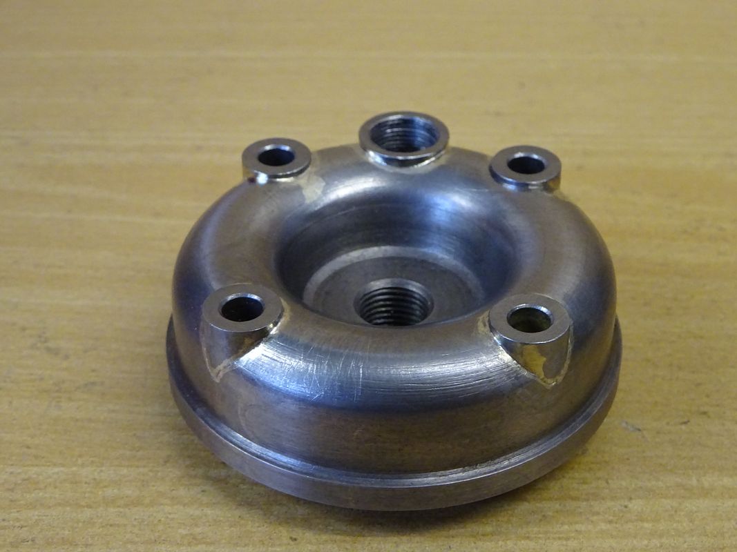
I have the head machined and ready for brazing, just need to replenish my acetylene first. (Concept attached.)

Today completed designing Rev 1a of the cylinder and components, starting to be convinced it is quite doable as a non casting.
Outside components are Mild Steel, inside is Cast Iron. Might change the Intake boss to Bronze.
Rough dimensions for those wondering the OD is 2" stock cleaned up to 1.94" OD at the flange overall length of this component Assy is 3".

The bore will be 1.125 ID.
 

Attachments

  • Note on Head Const.pdf
    165.4 KB
  • Cyllinder, pre-machined assy.pdf
    89.8 KB
Looks really good Ken. I’m thinking you could achieve the same result using something like J B weld. It’s good to around 500 degrees F and might be easier to manage making fillets?
 
Looks really good Ken. I’m thinking you could achieve the same result using something like J B weld. It’s good to around 500 degrees F and might be easier to manage making fillets?
Thanks Craig, for strength, my thought is to tack with TIG (I have an Miller Econo TIG) and fill with the 620 deg. Silver solder mentioned by jasonb, the JB Weld I'll use to obtain consistent fillets. It will all be painted Red any way.
Later this week end I'll post something where I have changed the component colors only to illustrate them in an assembly.
If there is interest I'd consider making detail drawings available at a modest price, but that will be after I've made an engine that runs (maybe by some time in 2022).
 
As promised here is how I plan to fabricate the three main parts that would most often be castings. Also is a photo of the head components which is ready for welding. On the welding, since I was out of acetylene I stopped in a my local Airgas supplier and ended up with Radnor 95/5 that has a 460 deg. melting point and purportedly will leave a controllable fillet (we shall see 😏).
The colors are only for illustration and communication purposes.
Cheers all, Ken
 

Attachments

  • BH000.pdf
    139.5 KB
  • BC000 ASSY-WELD-MACHINED.pdf
    500.8 KB
  • BS000 ASSEMBLY-WELDMENT-MACHINED.pdf
    401.2 KB
  • IMGP0015.JPG
    IMGP0015.JPG
    332.8 KB
Is there some form of porting within the head that means you have to use a separate "purple" part rather than just mill the "D" shaped recess into the "grey" outer head?

I'll be interested to see how the welding comes out, as I said it would be all silver soldering if I were doing it as I only have stick welding and am not that good.
 
Last edited:
Hi Ken.
I was wondering what compression ratio you were expecting. The 1/3 model from Tolsten Shure has a very low 2:1 compression and runs badly usually firing every other ignition stroke. To get it to run reasonably well I increased it nearer to 4:1. I filled in the D comletely and then some.

Tony
 
Is there some form of porting within the head that means you have to use a separate "purple" part rather than just mill the "D" shaped recess into the "grey" outer head?

I'll be interested to see how the welding comes out, as I said it would be all silver soldering if I were doing it as I only have stick welding and am not that good.
Jason,
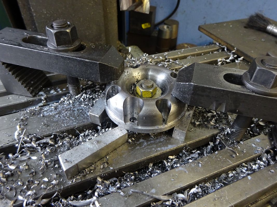
No there is no porting in the head, the valve at the top opens the passage to the exhaust, there is a slide valve that opens the fuel inlet. I felt it easier to make the 'D' shaped area a separate piece as that allowed me to clamp the 'housing' and turn the inside & outside (Photo attached.)

I have a Miller Econo TIG and am considering using it to 'Tack Weld' the components as that would allow me to clamp the components in the desired position, then I thinking a combination of silver solder and or the 95/5 that has a low melt temp, I want to be able to control the fillet. Of course I can accomplish that with JB weld. Now saying this, it strikes me as a good idea to use some scrap to see how the various processes work out - will do that tomorrow and post the results, along with a description of the process details. (Had not thought about that until doing this reply, Duh :rolleyes:.)

Tony, I have not worked out what the compression ratio is just yet as this is still the the design stage, will definitely think about how to reduce the volume in the 'D' area. If the 'D' area is completely filled how did you resolve the exhausting?
 

Attachments

  • Turn'g Head OD & Shoulder.JPG
    Turn'g Head OD & Shoulder.JPG
    352.2 KB
Tony, I have not worked out what the compression ratio is just yet as this is still the the design stage, will definitely think about how to reduce the volume in the 'D' area. If the 'D' area is completely filled how did you resolve the exhausting?

I bored out the head casting to remove the D shape, most of the flange, and flatten the inner face, I then made an insert with a flange to fill that space. The piston side of the insert is also spiggoted to reduce the space in the bore. There is a central exhaust port 6mm drill to just past the full depth of the valve. After loctiting the spigot in the head I bored the exhaust valve port 3mm past the 6mm hole.

In your case, and it's something I intend to do for the future, you could make the two piece head to include a water jacket.
Tony,

Great idea, I checked my original idea (Glad I have not welded anything yet! :)!), that cavity was .05 cu in, this redesign reduces that 20% to .04 cu in. Does not seem like a lot but in a model might make a huge difference. Now to the shop to re-remake that combustion chamber.
 

Attachments

  • BH000-2.pdf
    314.2 KB
That looks more like an 80% reduction as the cavity is a whole lot smaller now
 
Back
Top