Hey guys did my introduction and someone asked what scale i planned on making my engine to i didn't really place all the details in the intro post as i felt it should be really just that an introduction as to who i was and what i was here for.
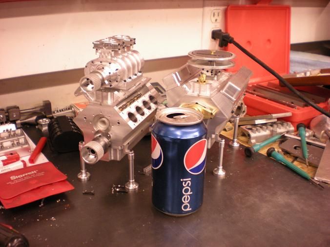
So now some details on the engine. Its more or less based on a ford 302 small block commonly known in the states as the 5.0 being a ford guy and that being one of my favorite engines of all time i decided i had to make one after seeing gbritnells awesome 1/3 scale one.
It seems i cant find my binder of drawings and dimensions at the moment probably downstairs in the garage. Anyways i followed the bore and stroke ratio of 4/3 and scaled down until i hit a displacement of 497cc or 30.2 ci 10% of full size. Now the bore and stroke of course isn't perfectly scaled in their new dimensions but the ratio matches and scaling volume doesn't work as easily as linear dimensions or area.
Let me say though that a perfect scale model of a ford 5.0 is not my primary goal the bigger goal was to match the displacement scale i wanted then of course lots of dimensions of the crank and cam and positions had to be scaled or i had to engineer it to work how i wanted.
I'm trying some new things not really common to full size engines or even really done on scale ones.
I'm not going to be using sleeves and cut in water jackets but instead I'm going to have a water jacket that closely follows the cylinders but its a complete groove around the top. My first though was to make some kind of sealing plate to seal the water jacket but that would just be a pain in the ass to say the least. So now comes some racing technology copper o-ring seals. All of the cylinders will have a .025 groove cut to allow for a copper o-ring of my design to be placed in and when the head is torqued down the ring will compress and hence for seal the cylinder to the heads combustion chamber while allowing for over the top water flow and cooling capacity.
I thought about ignition for a while now distributors obviously work as almost all engine use that setup but being that i want to go against the grain and do something different i was thing of do a crank trigger setup with coil packs. I know never seen on a scale engine and a bundle of extra work for something that wont really make a big difference. But hey if we don't try to do something different every once in a while we get complacent.
Now i doubt this hasn't been done but i cant really find any info about it. DRY SUMP oiling i wish i could give a good explanation of it for those who don't know but it is a much more effective form of oiling your engine which allows for bigger power gains and it allows the engine to work less to make the same power. Wet sump works but when i have to make most of the parts myself anyways why not go dry sump but for oiling passages I'm some what at a loss so any help is appreciated.
The heads are my nightmare at the moment because i don't have one to take dimensions off i mean LxWxH is meaning less cause i have changed things up but the angles i need at least the most common ones. Such as the angle of the intake ports versus flat line of the head and what angle the valves should be at vs flatline of the head. Ive been using 18* which seems ok but as stated its giving me a headache at this point and any incite would be great.
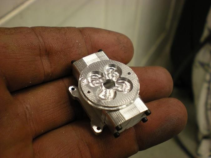
Fuel system is confusing me to i want to make 2 setups one that is N/A and a Boosted model. The N/A version i speak of is ITB essentially a carb for each cylinder. I have no idea what carbs to use or how to make my own for that matter. I'm thinking a decent r/c engine carb would work just find and i can easily obtain those. for the blower i wanted something like a 4 barrel Holley which i could make in theory but I'm not really a carb engineer and have no really grasp as to how to go about designing one.
I'm doing all my modeling within mastercam x5 not the best for modeling but being as i taught myself how to model about a month ago its more then enough. I have autocad, inventor, and solidworks but have no real experience with the latter 2 and the new interface in autocad annoys the hell out of me. Id like to get most of my modeling done then ill tolerate that new interface and start the drawings applying GD&T to all dimensions.
The goal of this project is to not only have a pretty working engine but to have it fully documented with plenty of photos and video. I will have multi view drawings of all parts with dimensions and solid model pictures to accompany them.
I want anyone with the desire to be able to recreate this. Once i have finished everything i will post it in the download section as a RAR file for free download to anyone interested that just a small donation from me and ill try to be fast about it.
Ill upload some photos of the solid model of the block and heads they are by no means finished and any advice is very welcomed. the block is really still in design phase and i feel that i have to much material in front and back of the cylinders as far as overall length goes but maybe I'm wrong


