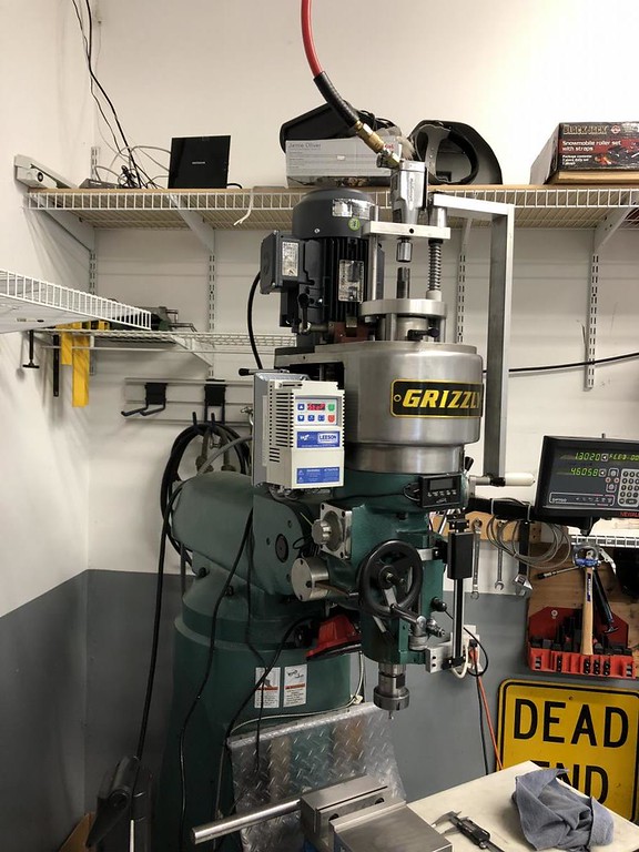
VFD on a Grizzly Mill

Home Model Engine Machinist Forum

Help Support Home Model Engine Machinist Forum:

This site may earn a commission from merchant affiliate links, including eBay, Amazon, and others.

Jmccrack

Well-Known Member
Joined
Feb 4, 2013
Messages
144
Reaction score
20
Hey guys just thought I would share. I installed a new 2hp 3ph motor on my Grizzly mill. As well a a Leeson VFD. Other than the fact the motor on the mill was metric and the motor I bought was all imperial the change over was very easy. Single phase 220 in and 3 phase out. The Leeson VFD has a number of parameters you can set for the way you want it to run, again very easy to program. It even has a parameter to cancell the drive hum, which was very nice. Here is a pic of my finished project. I would highly recommend doing it. SorrY for the sideways photo. I have not mastered that yet:

44AA4FBF-D6E5-4483-9EBD-D0818AB92505.jpg
 
Really like the drawbar setup. As for the sideways pictures.......if there is an answer I wish someone would post it. Cheers, Peter.
 
Very nice looking install. Was the new motor a comparable HP to the old one? I don't know much about that particular mill, but is it a sheave belt drive reduction between motor & spindle, or ?cant think of the proper name? where you turn up the spindle rpm with a handwheel & internally its linearly gearing on a set of cones? Reason I ask is - when you retrofit VFD do you just pick a middle gear ratio, leave it there & then the VFD gives you +/- rpm from that? What is the rpm range you have now?
Hopefully I haven't confused you :)
 
The motor I replaced was a 2hp 220 V single phase. I replaced it with a 2hp 3 phase. The mill is a single belt from the motor pulley to the spindle. The motor I used is 1750 RPM so I just place the belt on a 1 to 1 ratio. So at top speed I have 1750 on the spindle. So now I have 0 to 1750 RPM. But I have the ability to move the belt up and have 2400 RPM if I need it. I can not get over how easy it was to do. It is so nice not to have to move a belt on a pulley to change speed. The mill has a low gear range so if I am drilling a 1” or so hole I can used low range and speed up the VFD and not lose any torque. If anyone out there wants to change single phase to 3 phase a VFD is the way to go. Up to 3 HP of course. The VFD has a setting for Hertz as well as RPM.
 
My BP has a pulley with three sheaves, and I leave the pulley on the center. RPM at 60Hz is 2100, so I set the VFD to show that RPM at 60 Hz. I never move the belt. Back gear for slower speed. It is OK to overspeed these motors for a few minutes at a time, so the upper limit can be increased in the VFD.
 
I would try to enclose the vfd, can't tell if you have a fast acting fuses or circuit breaker(
EATON FAZ-C3/2-NA Miniature Circuit Breaker, 3A, C curve) before the vfd, cheap insurance.
Running the vfd at 80 hz is a way to increase speed without belt changes.
 
Very slick. Did the motor have the same size mounting, or did you have some mechanical modifications to make?

I have a smaller Grizzly mill, the G0704, and one of the things I want to do is upgrade the motor. It has a max speed of 2200 RPM, and I'd like to double that. More importantly, I'd like to get the motor under CNC control to start/stop, and set speed.
 
Now that the picture orientation is correct I notice that you have the mill positioned diagonally in the corner of your shop. Good move as I have the same for my J Head along with table protection similar to yours. The big difference is that my shop is not as clean and my DRO units are a generation older.

Thanks for sharing the success of your motor upgrade.
 
I may be wrong but I was told to keep the VFD at a 10% up or down and it would last a long time. I run my mill at 45 htz to 80 htz. I have not had any problem with it for 2 years now.
 
I have a smaller Grizzly mill, the G0704, and one of the things I want to do is upgrade the motor. It has a max speed of 2200 RPM, and I'd like to double that. More importantly, I'd like to get the motor under CNC control to start/stop, and set speed.

Be careful with that, and pay attention to the spindle bearing rpm ratings.
 
When I hooked up my motor the VFD it was set on a slow ramp up and slow ramp down. I wired it to the motor to make sure it would work. It did not work and I was so upset, then I thought to check the motor wiring. There was the problem it was wired for 408 three phase. I rewired the motor for 208 and it worked fine. I turn on the VFD and the motor took a little bit of time to get a good spin going and it did not take long to hit the stop button when it got over 90 htz. I went through the booklet to set it up properly and set it to 80 htz, started it up again and it started spinning up to full speed then I hit the reverse and it ramped down changed direction and ramped up. How sweet! Hooking up a remote box on the machine made it even sweeter.
Nelson

Any of the new mills and lathes bearings should be able to handle 2500 rpm
 
Any one wanting to spin anything that fast is playing games. I would hate to see a tool come apart or metal flying at that speed. High speeds are good for one thing and that is very small drill and end mills. Spinning anything on the lathe would require carbide or more durable cutters and a very rigid machine. I really do not see any real need for more speed than the 2500 and that is rather high. Remember we are working on metal and not wood.
 
Spinning anything on the lathe would require carbide or more durable cutters and a very rigid machine. I really do not see any real need for more speed than the 2500 and that is rather high. Remember we are working on metal and not wood.

Oh, I totally agree. I was just saying the spindle won't last long doubling it. 2500 is fast!
 
i was under the impression that we are talking a milling machine here. If so there are plenty of times where a high speed spindle is the right answer. This is even more so if the Mill is to be CNC'ed. Even manually running ver small cutters and burrs on a Bridgeport can often benefit from higher spindle RPMs.

As for safety, lets face it most home shop machinist are rather lax in that regard. If OSHA had jurisdiction they would close down many of our shops.

By the way lathes are in fact a far bigger safety issue when it comes to spindle speed. That is why commercial CNC lathes often have bullet proof glass backed up by steel bars. Still that doesn't mean high spindle speeds are always bad. This is model engineering and tiny parts and holes are very common. In the end the user must select what is proper.


Any one wanting to spin anything that fast is playing games. I would hate to see a tool come apart or metal flying at that speed. High speeds are good for one thing and that is very small drill and end mills. Spinning anything on the lathe would require carbide or more durable cutters and a very rigid machine. I really do not see any real need for more speed than the 2500 and that is rather high. Remember we are working on metal and not wood.
 
CFLBob. I had to make an adaptor plate from the motor to the machine , but no big deal.
 
I have been using a VFD on my Bridgeport mill for several years, and it works great. There are a couple of things to keep in mind however. First you can slow the motor way down by lowering the frequency, but there are practical limits. The motor torque drops off at lower frequencies, and I have found 20 Hz to be a reasonable lower limit for light machining.
The reason for the lower torque is quite simple, the output voltage must be reduced at lower frequencies. The reason for this is that the motor (and any iron core transformer) has an iron core in the armature, and iron will reach magnetic saturation (i.e. all the magnetic dipoles are aligned) at a particular product of time and voltage (volt*seconds). Saturation is a function of the type of iron and the physical size of the iron core, and the size is designed to handle 50 or 60 Hz voltage normally. If the iron saturates, the current will increase very rapidly, causing heating and frequently circuit breaker tripping or other overload conditions.
In an AC motor or transformer the current reverses after one-half cycle of the AC voltage, and the magnetic poles then begin to reverse direction heading toward saturation in the opposite direction. Since at lower frequencies the voltage is applied for longer time, the voltage must be reduced, thus reducing the motor torque.
At 30 Hz the voltage must be reduced to half the design voltage (on a 60 Hz motor) to be safe and avoid saturation. The resulting current will be about the same as at 60 Hz, so the power of the motor (Volts * Amps) is reduced to about half the rated value. A nominal 3 HP motor (at 60 Hz) will produce about 1.5 HP at 30 Hz, and about 1 HP at 20 Hz.
Likewise at higher frequencies than 60 Hz, the output voltage must be increased above the rated motor voltage to produce the rated power. At some point the motor may be damaged either from the higher voltage or operating at a speed above the design value. Perhaps the motor bearings or spindle bearings will reach their design limit, or the motor armature may be damaged by centrifugal force.
 

Latest posts

Back
Top