V-TWIN---MAYBE V-4

Home Model Engine Machinist Forum

Help Support Home Model Engine Machinist Forum:

This site may earn a commission from merchant affiliate links, including eBay, Amazon, and others.
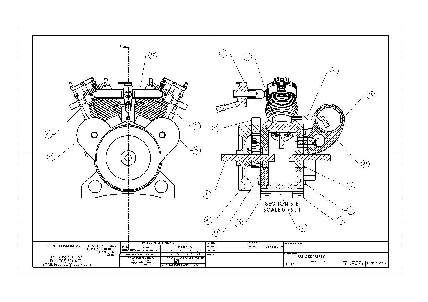
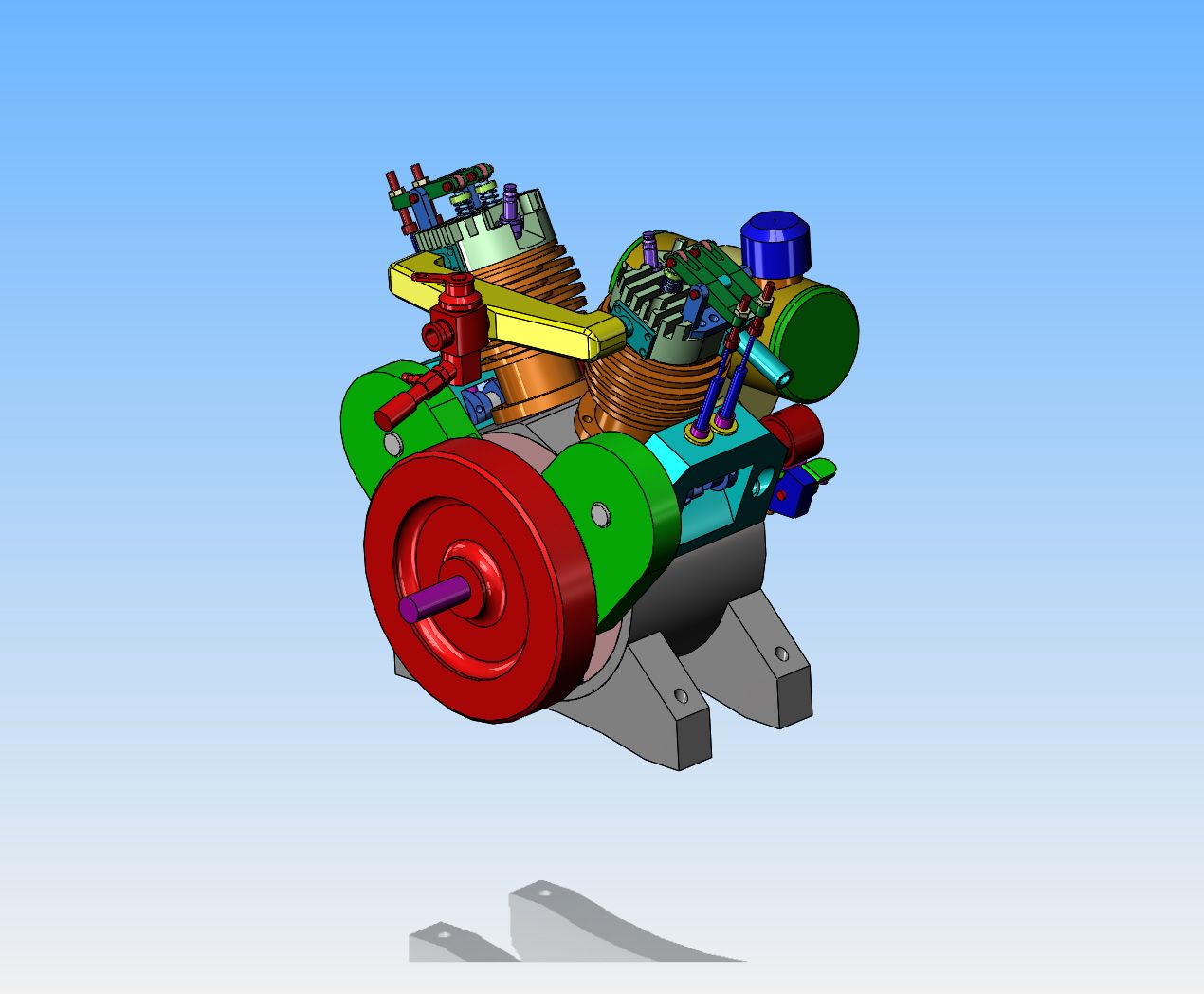
I went to bed last night, and as I lay there thinking about this engine, I realized that I had neglected to put a flywheel on it. Okay, that lets me get rid of the Mickey Mouse ears gear guard and put two smaller gear guards on--The rest of the gears are covered by the flywheel. I like this much better.
fTl5Li.jpg
 
Brian,

I like the way it looks with the flywheel too.

I definitely want to watch you build it: I'll be watching.

A V4 version would also be wonderful, but it would obviously take longer. Maybe that would be tiring for both of us........... (wink)

--ShopShoe
 
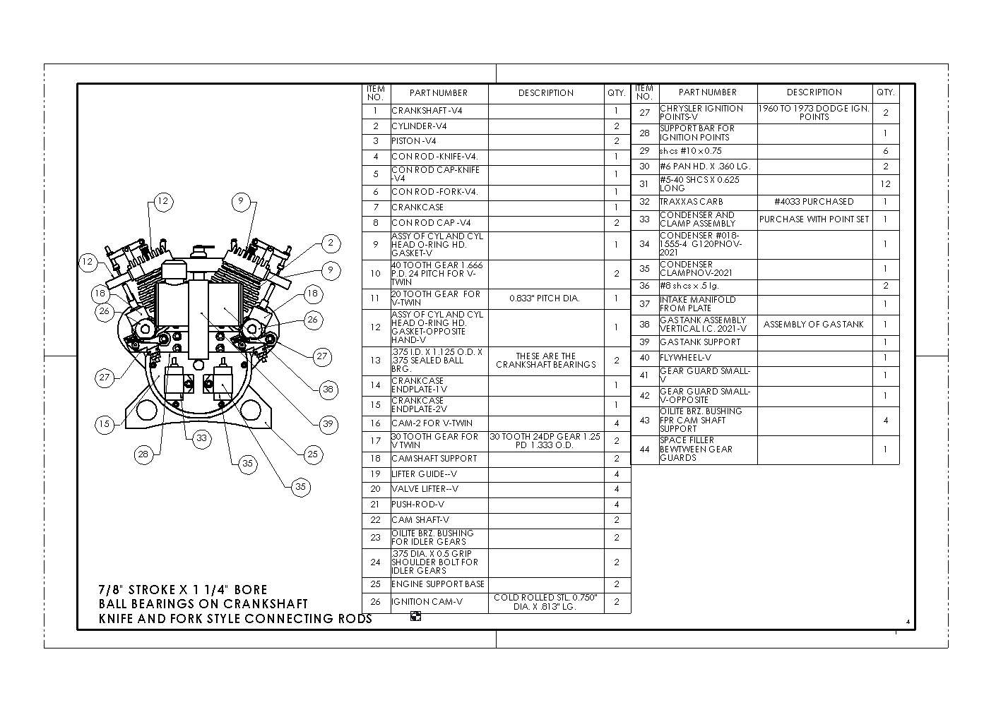
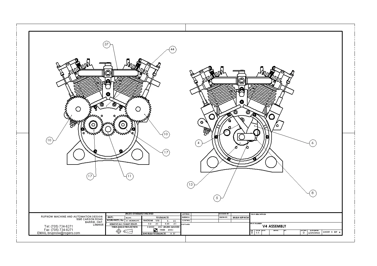
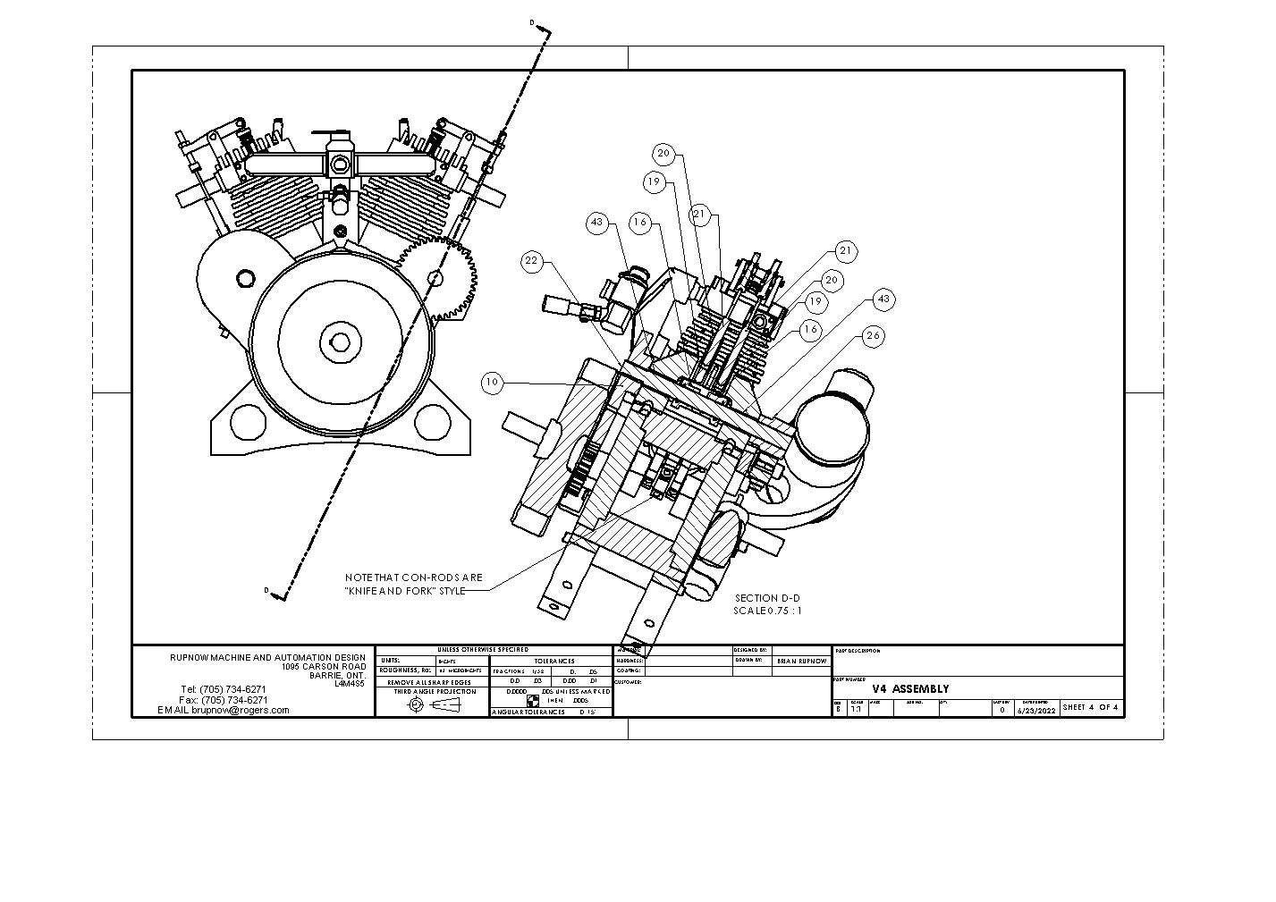
Ghosty--I've been thinking of why I didn't put the cam between the cylinders like you did. My cylinders are directly opposite each other, using knife and fork style connecting rods. That means that my valves and cams are directly opposite each other also. I need four separate cams to do this, layed out as I show them in my model. I couldn't squeeze all the cams onto one central camshaft.
 
Should not be a problem, you would only need a camshaft about 1" long and just let the pushrods run at an angle. The rods would run straighter than say a Hoglet and cam shaft would be no longer.
 
Today I thought about pricing brass to use for my flywheel and gas tank. The one supplier I contacted in Barrie, wants $25 for a piece of 4" round brass 1" long (My flywheel). I then tried to find a piece of 1 3/4" round brass to use for a gas tank. Best price I could get was $40 for a piece 3 1/8" long. Not really complicated parts to make, but I like the color contrast. Okay, maybe I'll try something else.--I did a web search for cans of metallic spray paints that are a close match for brass. A spray can of "metallic brass finish" costs $10.00. Hot rolled steel for the flywheel and and thin wall steel tubing for the gas tank are so cheap that they almost give it away. In fact, I have some lying around in my materials bin. So---Use hot rolled steel that is essentially free (because I have it) and $10 for some spray paint, or $65 for material to make flywheel and gas tank. The only thing I gain by using brass is that I find it much easier to machine. Somehow it feels a bit like I'm cheating to make something from steel and then painting it to look like brass, but that's a heck of a big price differential.
 
Ghosty--I've been thinking of why I didn't put the cam between the cylinders like you did. My cylinders are directly opposite each other, using knife and fork style connecting rods. That means that my valves and cams are directly opposite each other also. I need four separate cams to do this, layed out as I show them in my model. I couldn't squeeze all the cams onto one central camshaft.
On the Harley 45 Flathead they had 4 cams under the cam cover to run the 2 sets of valves . Must have worked ok seeing as how they made that engine up until 1973 .
animal
 
Ghosty--I've been thinking of why I didn't put the cam between the cylinders like you did. My cylinders are directly opposite each other, using knife and fork style connecting rods. That means that my valves and cams are directly opposite each other also. I need four separate cams to do this, layed out as I show them in my model. I couldn't squeeze all the cams onto one central camshaft.
Brian, if the tappets are at the same V angle as the cylinders, you only need two cams. One inlet for both cylinders and one exhaust.
I used this principal on my boxer twin.
 
Today I finished detail drawings of all the engine parts. There are 35 drawings including the overall general arrangement. I like the dual exposed camshafts. It is probably a bit more work to do it this way than with a single center camshaft, but I like the "mechanical" look of it. The extra gears aren't as big an issue as you would think. I just cut my stock extra long when I cut the 24 dp. gears and then part off as many as I need. I've done a bit of preliminary pricing of material, but haven't done any machine work.
 
Brian
Damn you have been a busy guy you even have a BOM made up. Very nice work can’t wait to see this start taking shape
Tom
 
Badhippie--I love to take the credit, but actually the software does that for me. It's almost like magic.---Brian
 
Brian
You can go ahead and take the credit someone still has to input it all. I won’t tell anyone lol.
can’t wait to see the results.
Good Luck
Tom
 
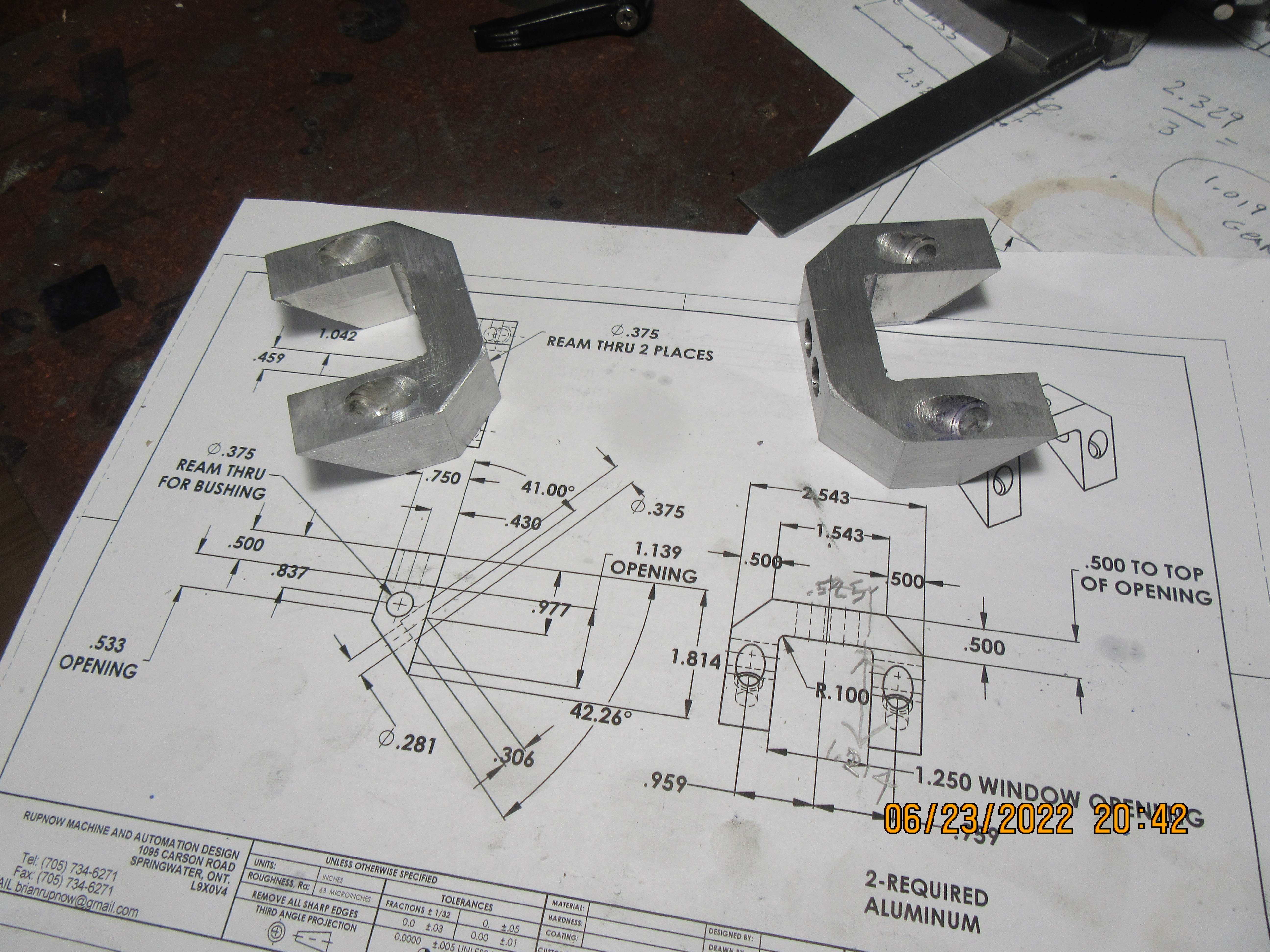
I had to break down and machine something today. I've read every book in the local library, downloaded everything that I would like to read on my tablet, and done all the household chores my good wife could think of. I actually caught myself reading a book about Zombies today, and decided "Oh boy--Better go machine something.----Zombies---Oh Lord!!!" So, first parts today---Camshaft supports. I still have some finessing to do on them, and I won't drill the shaft holes until after the main crankcase and gears are made.--I've been caught out on this one before. Far wiser to let the gears determine where the hole for the shafts will be. I know where they go dimension wise, but anytime there is a possibility of stacked up tolerances, it is better to assemble the gears and center-punch thru the bore to get a true center distance.
UxuqaF.jpg
 
This is like starting a new detective novel. You can guess the plot, but the details will turn up some surprises, before reaching (usually) a happy ending that just makes you smile.
Keep up the good work Brian.
K2
 
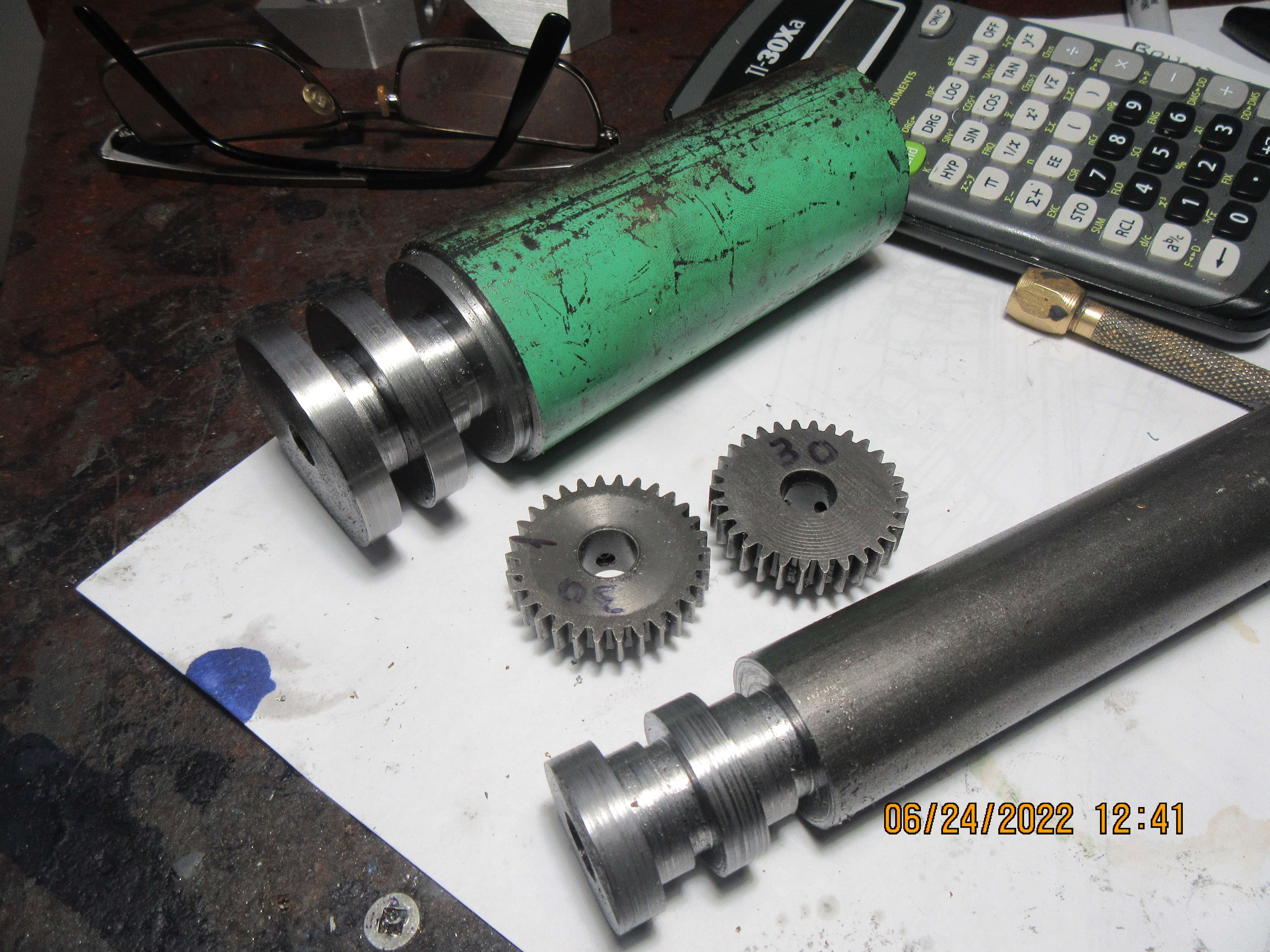
Today I'm playing with gears. I have a full set of 24DP gear cutters, which seem to fit the size of engines I build very well. I also have a drawer full of random gears that have been recovered from abandoned projects. This little treasure chest of gears yielded two of the 30 tooth gears that I will need. I prepared a 1" diameter piece of cold rolled steel so that I can cut two 20 tooth gears from it. I only need one, the second will go into my drawer of spare gears. I prepared a piece of 1 3/4" stress proof steel to become two 40 tooth gears. In a perfect world, I would have made the idler gears out of brass, because there is a theory out there that gears of dissimilar metals run quieter. However, since I have the two 30 tooth idler gears already, they are what will be used. Next step will be to set up my rotary table and milling machine to cut teeth on the gears.
Y3nXFP.jpg
 

Latest posts

Back
Top