Throttle governed engine

Home Model Engine Machinist Forum

Help Support Home Model Engine Machinist Forum:

This site may earn a commission from merchant affiliate links, including eBay, Amazon, and others.
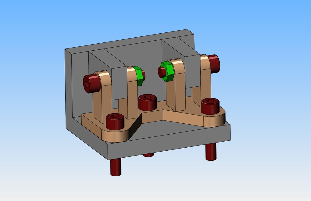
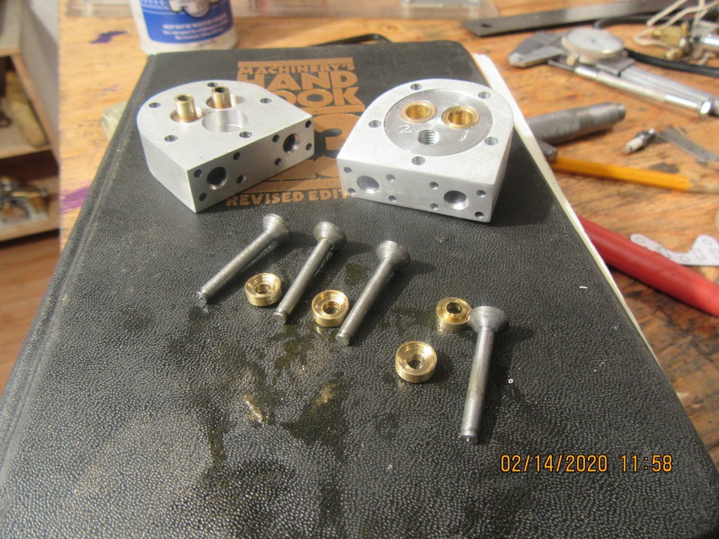
So, the valves, valve cages and valve spring retainers are finished. The valves have been lapped with #320 then #400, then #600 lapping paste and have been match marked to their specific place in the heads so that I don't mix them up. I'm coming down to the exciting strokes now. I will first design and build a fixture to hold all of the parts of the rocker arm bracket in the correct relationship and silver solder it together.
tTLsh9.jpg
 
That should do the job! Unless ... wait: how will you affix the "arms" on that welding / soldering fixture? Will they be soldered? If so, you'll need a welding / soldering fixture to make the welding / soldering fixture. And then you may need another fixture to make that one, and ... oh, my head hurts.

:):):)
 
Awake--I like making welding fixtures. I designed welding fixtures for many years for tier 1, 2, and 3 automotive parts suppliers. Some of them were just insane, and would cost more than a new car.---Brian
 
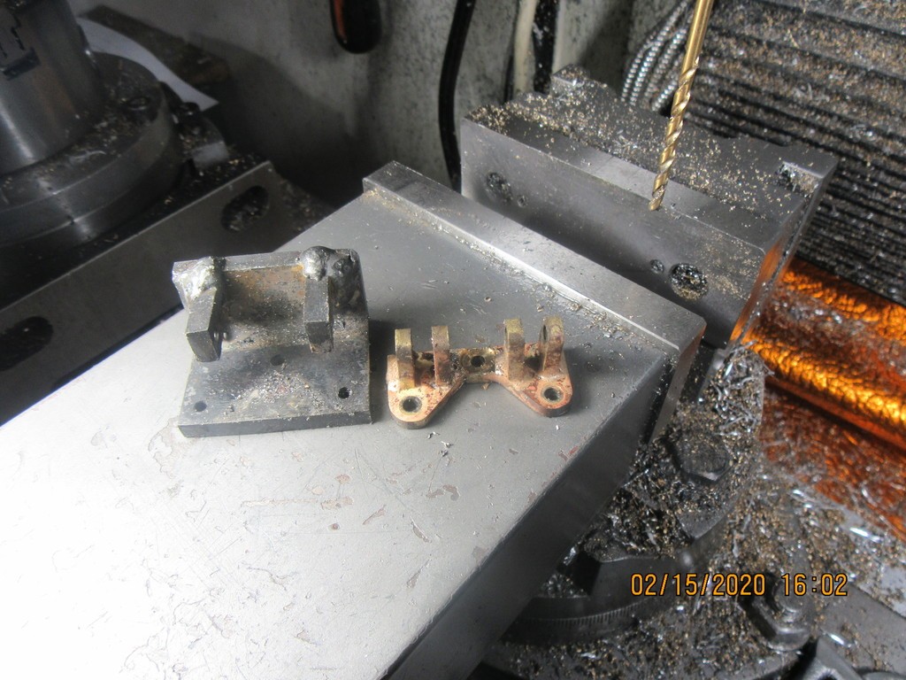
Awake--No offence taken. I really do like to design welding fixtures. When used in mass production of welded parts, either by a human welder or by a robot, they give truly astonishing speed and repeatability. They don't make a lot of sense for small "one off" jobs, but sometimes there are just no other ways to align all of the parts for soldering. I spent about two hours designing and building the one I just finished, and will post pictures of it with the soldered pieces in place tomorrow.---Brian
 
Brian, I couldn't agree more. As a retired aerospace tooling/manufacturing engineer with 30 years experience I can attest that a properly designed welding fixture is indispensable for accuracy and repeatability in a production environment. In the hobby environment they help to ensure accuracy in a one-off situation. Loren
 
I fully agree on the value of fixturing - that is one of the particularly helpful things to see on this forum, how to accomplish the machining of a part (or in this case, the joining of parts) that otherwise looks impossible!
 
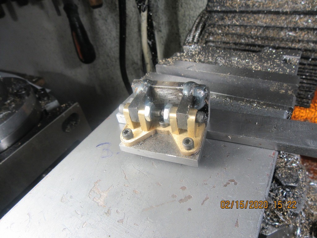
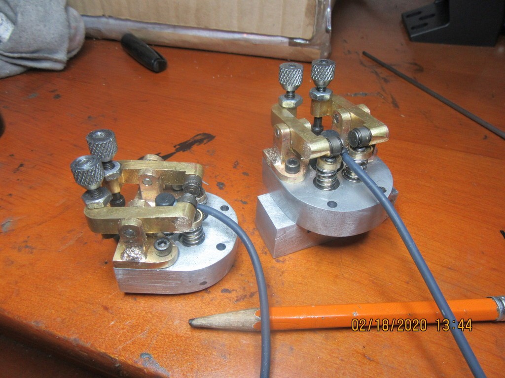
This picture shows the finished welding fixture. (Remember, it doesn't have to be pretty, just functional). The brass pieces which will be silver soldered together are bolted into place and are ready for soldering. If I have lived right, the fully soldered assembly will be easily removed form the welding fixture, and the pieces for the second brass rocker bracket will fit into it for soldering.
x2JMss.jpg
 
Bob--If you asked a dozen people about silver soldering, you would get a dozen different answers. This is what works and doesn't work for me. I tried propane, but could never get things hot enough to work right. I use my old oxy-acetylene rig with a smaller torch tip (it came with three different size tips when I bought it 40 years ago). I clean anything to be soldered until there are no visible oxidization on the parts to be soldered. Sandpaper and wire brush for cleaning the brass or steel. I use a paste style of flux (Stay-Silv from Harris) applied directly to where I want the solder to be. I use 1/16" diameter silver solder, which comes as roll of "wire". I direct the torch flame directly onto the brass where I want the solder to flow, and heat it to a dull glow (I have no idea what temperature that is.) I keep "dabbing" the end of the silver solder against the joint until it flows. Try not to get too much flame onto the silver solder as you do this or it will melt and run away in a puddle. As soon as the solder flows, work your way around the part being soldered. This is kind of a delicate dance like ballet---If you get it too hot, the brass will melt. If you get it too cold, the solder won't flow. Try to keep the parts being soldered away from any big pieces of metal that will act as a heat sink and suck all the heat out of the parts. (A vice for instance).---This is easier said than done. If there are places where you don't want the solder to flow, coat the area with liquid "White out" for fixing typewriter errors. I always work from the point of view that too much solder can be filed off. Too little solder can result in a bad joint and will have to be resoldered. And that is just about everything I can tell you about silver soldering.---Brian
 
I've done silversmithing in the past, about 15 years ago was the last time I did it. I was actually pretty good at making jewelry without getting solder everywhere and having it stay together in a finished piece. Silversmiths use different solders, usually called Easy, Medium and Hard (there are other grades) and sterling silver melts at fairly similar temperatures to the brasses. Hard silver solder is the highest melting point and silversmiths often consider it a point of pride to make a piece completely with hard solder while the beginner schools teach to make the first joints with hard solder and use lower melting points for successive soldering. If you make something completely with hard solder, anyone who has to repair it will have less issues with things re-flowing and moving.

I still have an acetylene-air torch. I need to clean it out because this is Florida and there's no telling what has made nests in or laid eggs in it, probably a Burmese python (nah - they wouldn't fit). I need to brush up on soldering and get some of the wire solder that's used in this sort of work. I mostly need to learn the differences in what's used and do a few practice pieces.
 
Everything fits like the 3D model says it would. Not a lot of spare room, but a miss is as good s a mile. Tomorrow I will make up the hardened rollers which bear against the end of the valve stems, and the axles that the rocker arms pivot on.
PscY3W.jpg
 
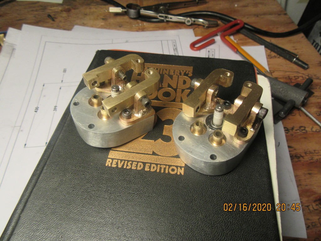
The new cylinder heads are completely finished and assembled. Everything fits, but there isn't very much real estate left anywhere. For those who were wondering, the compression springs are made from 0.020" wire, and are purchased. The valves are lapped and held in place by circlips. The next move will be to remove the existing cylinder heads from the engine and install the new ones.
Oq8gBM.jpg
 
All of the moving components could probably have been made of aluminum. Aluminum weighs almost exactly 1/3 of what brass weighs. I was limited to brass for the bracket, because I don't have the equipment to weld or solder aluminum. Would the difference in the way the engine runs have been measurable?---Probably not, at the speed I am asking it for. The original heads were aluminum, the original rockers were steel, and the original knurled adjusters were brass. The new heads are aluminum, the new rockers are brass, and the new knurled adjusters are mild steel. The engine in it's original form ran very well, but there was always a problem on cold starts--oil would separate from the fuel and foul the sparkplugs, because they were right at the very bottom of the cylinder. I'm not reinventing the wheel with these new heads, All I'm doing is correcting what I determined was a design flaw. I haven't dismantled anything from the old heads, the design flaw only appeared when the cylinders were horizontal. The old heads may get re-used on a new engine with multiple vertical cylinders.
 
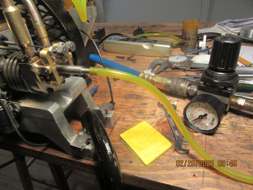
People have been asking about the relative size the engine is that I am working on. Canadians don't use pennies anymore, so the only closest thing I could find for a visual comparison is a matchbook. In this picture, I have my adapter screwed into the sparkplug hole and 50 psi on the air hose. No leaks at the exhaust pipe nor the carb air intake. Having established that cylinder as being okay, I will now move over to the other cylinder and perform some magic over there.
EiYQPF.jpg
 
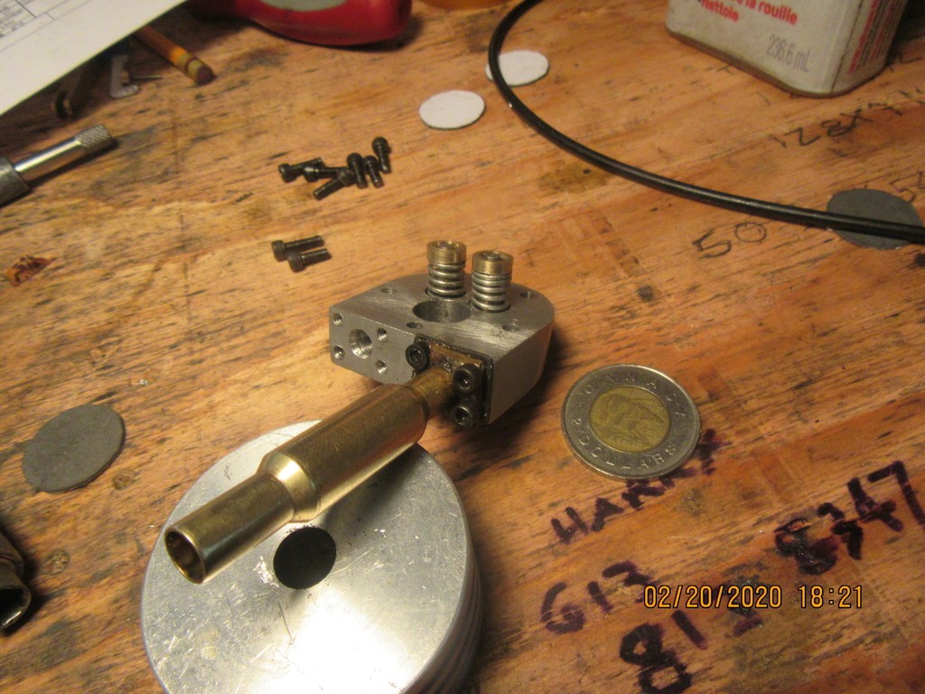
I had an interesting day today. I went to a heavier valve spring of .038" wire diameter. These are beefy little buggers. Too strong to compress with my thumbs and slide the locking collar into place. I had to figure out how to make a spring compressor. Honestly, I have never used any springs that are over 0.020" diameter on any of my engines. The "lift" on the cams for this engine is just a bit more than 1/16". The coin is a Canadian $2, called a "Twoney"--that name was derived form the 1$ coin issued a few years ago that had a loon on one side, so of course it immediately got named a Looney!!!
fsichH.jpg
 

Latest posts

Back
Top