The Artful Bodger
Member
- Joined
- Aug 26, 2009
- Messages
- 24
- Reaction score
- 0
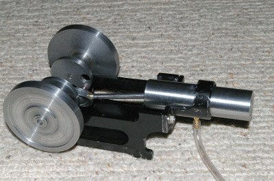
For my first serious attempt at metal turning I decided to design and make a little steam/compressed air engine. Although the principle of rotating the piston to get the necessary port timing is not new I have not seen anyone do it the way I did!
Concept:
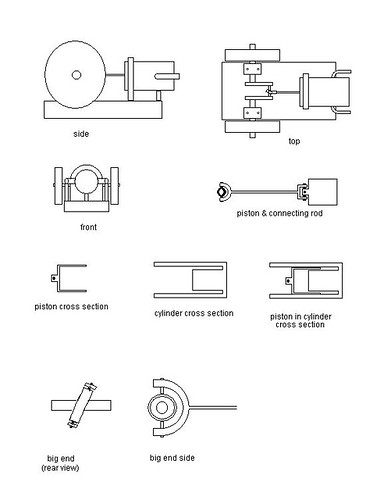
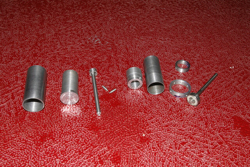
Some of the components:
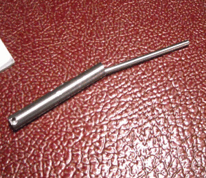
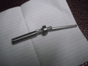
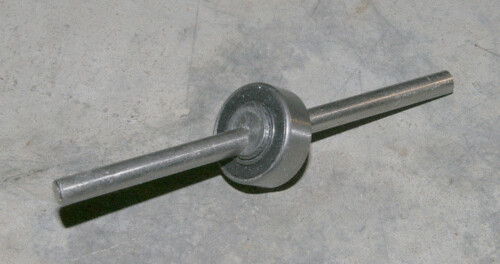
The 'nutating' big end bearing
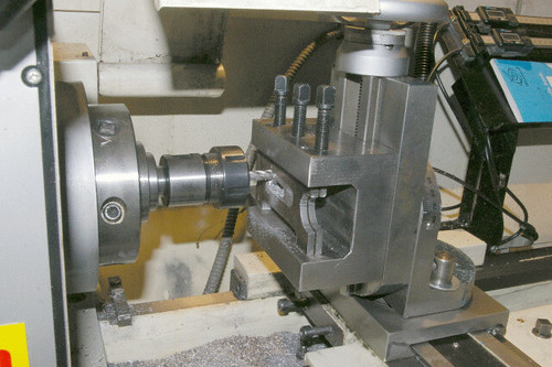
Milling the side frames in my lathe
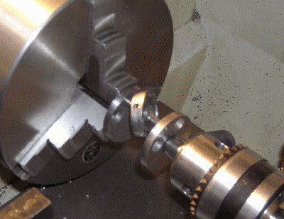
The crank shaft is assembled, I took the easy way and used adhesives.
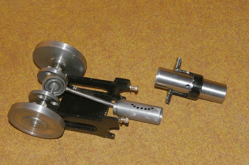
All the bits together in one place
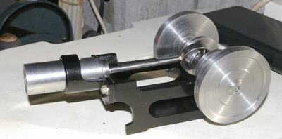
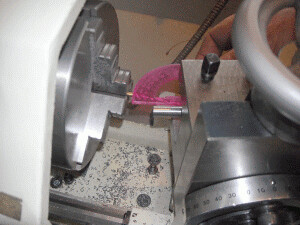
Marking the position of the exhaust port, I put the felt pen in the cylinder port and turned the engine through one revolution.
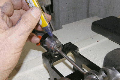
The cylinder was drawn aside and this is the shape that appeared on the piston sleeve.
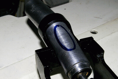
Just before final assembly, the row of exhaust ports drilled in the piston sleeve and the cylinder port visible in the cylinder. The inlet port is at the bottom of the cylinder and has been drilled in the same manner but obviously covering the other half of the cycle.
Sorry but my camera froze the action so you will just have to take my word for it that here it is running!
Concept:

Some of the components:

The 'nutating' big end bearing

Milling the side frames in my lathe

The crank shaft is assembled, I took the easy way and used adhesives.

All the bits together in one place

Marking the position of the exhaust port, I put the felt pen in the cylinder port and turned the engine through one revolution.

The cylinder was drawn aside and this is the shape that appeared on the piston sleeve.

Just before final assembly, the row of exhaust ports drilled in the piston sleeve and the cylinder port visible in the cylinder. The inlet port is at the bottom of the cylinder and has been drilled in the same manner but obviously covering the other half of the cycle.

Sorry but my camera froze the action so you will just have to take my word for it that here it is running!


