Tacchella AU300 universal tool grinder

Home Model Engine Machinist Forum

Help Support Home Model Engine Machinist Forum:

This site may earn a commission from merchant affiliate links, including eBay, Amazon, and others.

coopertje

Project of the Month Winner!!!
Project of the Month Winner
Joined
Jul 3, 2010
Messages
278
Reaction score
10
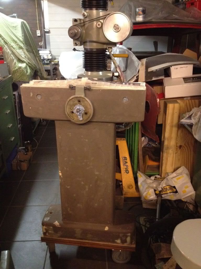
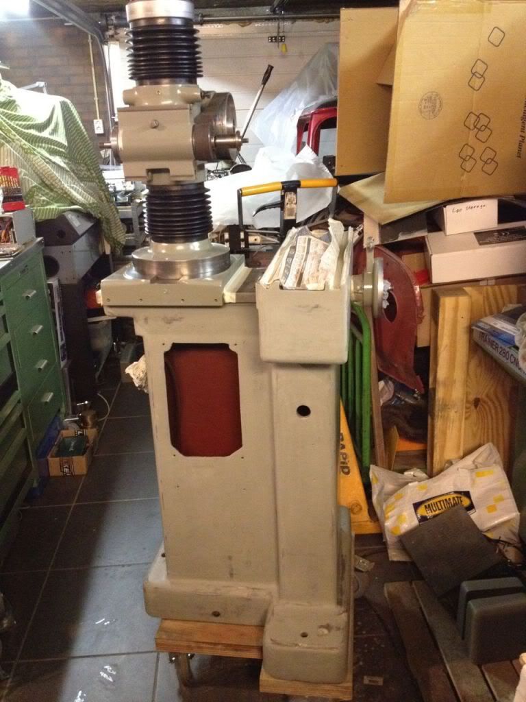
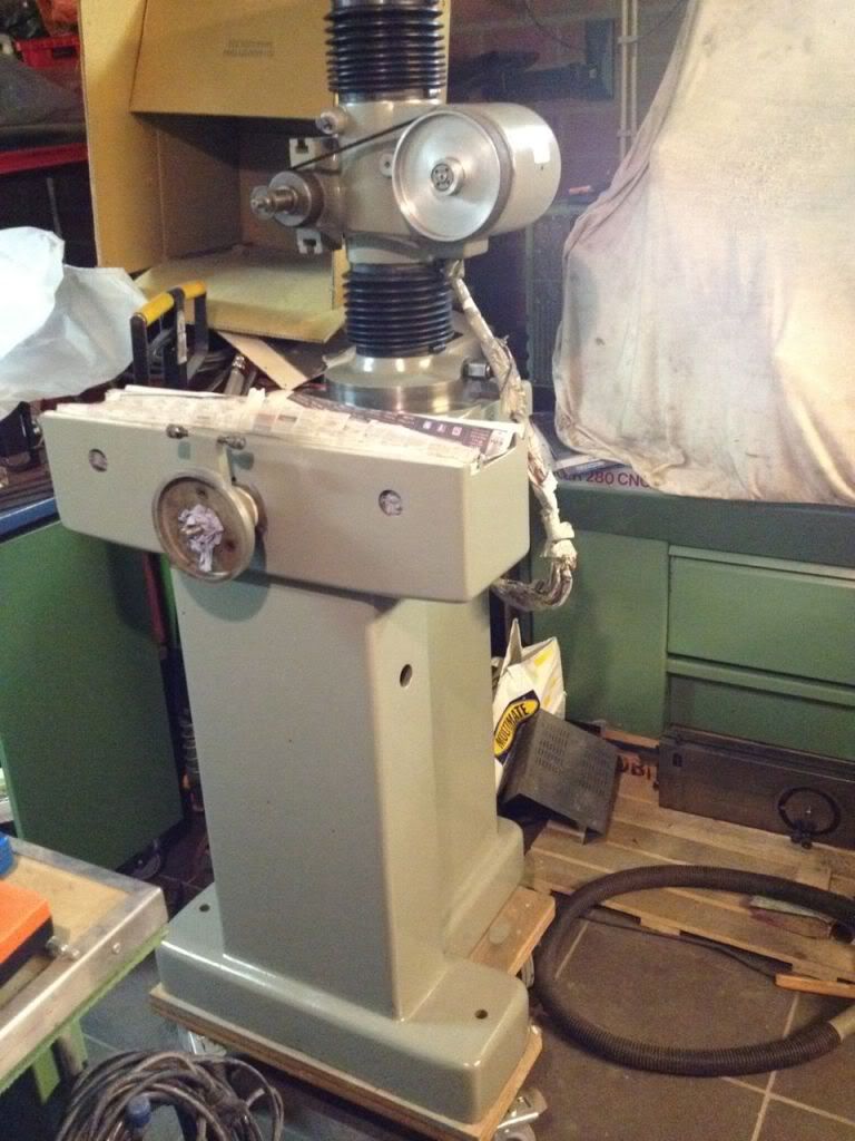
It has been a little while since I have posted progress on the Stuart 10H build. The reason is that I found a nice grinding machine, I have a lathe (manual and CNC), milling machine (manual and CNC) but did not have a decent grinding machine yet. I was looking for something small (shop is becoming full) and preferable able to sharpen all kinds of tools, center grinding and light surface grinding. I just passed by a used machine dealer and found the Tacchella AU-300. It seems to meet all my requirements, came together with about 15 grinding wheels, a full set of collets and the original dIviding head to sharpen end mills. It's a very stable build machine (375kg) and although its quite old (included original test report dated 1961) it is mechanically in a very good shape. A quick measurement over the table indicated a deviation so small that with the equipment I have available I cannot measure it!

Below some pictures of the machine as purchased and partly disassembled

DSC_0936.jpg


DSC_0937.jpg


DSC_0938.jpg


The original mill holder with indexing

DSC_0930.jpg


DSC_0931.jpg


I want to take the machine apart to check everything and also it needs a paint job, the original paint is completely worn out. As you can see below the table has some kind of linear guide

DSC_0940.jpg


Started cleaning, plastering and sanding the base and the grinding head

DSC_0942.jpg


Ground layer and spray RAL-7003

DSC_0943.jpg


DSC_0944.jpg


After cleaned, plastered and sanded all the peripheral equipment

DSC_0945.jpg


DSC_0945a.jpg


Used a cardboard box with shop vacuum cleaner as a spraying cabinet, worked out very well!

DSC_0945c.jpg


DSC_0946.jpg


Ground layer and after sanding again (wet 400 grid) spray the final color

DSC_0947.jpg


DSC_0949.jpg


DSC_0949a.jpg


DSC_0949b.jpg


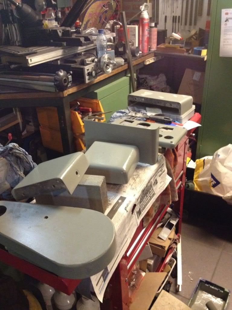
Some finished parts

DSC_0950.jpg


DSC_0951.jpg


DSC_0961.jpg


Grounding the base and additional parts
DSC_961c.jpg


DSC_961a.jpg


DSC_961d.jpg


DSC_961b.jpg


When I am back home, I am on holiday now I will paint the base and reassemble the machine. I am also having thoughts about a grindingrest to sharpen drills, lathe tools and radius tools. Nice to kill the time in holiday...

Regards Jeroen
 

Nice job shoe horning that piece in there! The restoration looks good too.

I'm sure the machine will easily last another 50 years.

Nice floors too!
 
Thanks Kevin, I did not think I had space for the machine, but the motivation was enough to create the space needed. Its placed on wheels so I can move it when I need to get something from the back of the shop. Not optimal but it will do for me.
 
That x-axis roller bearing way system is pretty cool. Do most surface grinders use a setup like that?

Chuck
 
cfellows said:
That x-axis roller bearing way system is pretty cool. Do most surface grinders use a setup like that?

Chuck

YUP some jig borers too....Moore to name one.

Dave
 
I am jealous ;) dam nice machine and nice tune up you did. :bow:
 

A very nice addition to your shop. A high quality universal grinder like this can handle tool and cutter sharpening, surface grinding,
OD grinding and other operations I can't even remember. Great looking paint job also.

Regards,
Mike
 
Thanks for the comments! The ones that I know all have some kind of linear guide for the X-axis. I guess it has to do with finish of the grinded workpiece. The more smooth you can get it passing the grinding wheel, the better the finish will be. Another thought might be that if you are able to pass it with a reasonable speed the heat in the workpiece will be minimum (and equally spread). If somebody knows the real reason for this kind of construction I am interested to learn. I have a Weldon end mill sharping jig to sharpen the flutes of an end mill. It has an aerostatic bearing, in a way that can be compared with the linear guide of the X-axis. So it must serve some purpose, otherwise they will not go through all the trouble to construct it this way.

I hope the groundlayer will be dry when I return home, I saw on the net that the temperature in Holland dropped below 0 this week. Not very good for paint to dry and harden.... :-\

Below a very rough sketch of my idea of a universal support for tool, drill and radius tooling

grindingjig.jpg


In the bottom part there is a 3D angle adjustment to set all the required angles when sharpening cutters and drills. In the middle there is a free rotation point (with locking possibility) for making a radius on a cutter. To set the radius and adjust the position of the radius on the cutter (center, left/right side) I will have a small X-Y adjustment on top. I am not sure if I have enough height available for this tower, I have to measure when I return home.
Your comments, ideas, improvements etc are very much appreciated, it will be quite some work to make the jig and I prefer to make the correct one first time!

Regards Jeroen


I just finished renovating a Tacchella 40L at work, lovely universal grinder, the table was out by 0,03 mm, not much, but far too much when the grinder are used to grind 0,01 mm air vents in plastic injection moulds. i changed all rollers, and gave the table a turn on the large grinder
 
Hi Holt,

If my table is out for 0.003mm I will jump from happiness. I am probably even not able to measure such a runout with a 0.01mm resolution meter. The base table I cannot measure any runout with tools available, I have my doubts about the upper table, I had a large runout on that one 0.3mm over 100mm distance. But when disassembling the machine I found a lot of grease and dirt between the 2 tables, hope that is the reason for runout. If not, I have to find a "friend" with a big grinder to straighten the upper table ;D

By the way, do you know how to use the machine for OD grinding? I understand to place the workpiece between the centers, but then... is it rotated by hand or is there some kind of jig between the workpiece and centers?

Thanks, regards Jeroen
 
Sorry, i just saw i was too generous with the zeros, it was 0,03mm runout. our grinder came with a motor attachment, with r-8 collets, 3 jaw and a magnet + several other items
 
That 1 extra zero make a big difference! :big:

Ok, get the point. The workpiece is motor driven. So the machine probably has that kind of center with a double function, center and at the same time drive the workpiece. That should not be so hard to make. However a picture of this original motor and centers (your 40L) would be very nice!

Regards Jeroen
 
I will try to remember to take some pics in the near future (tomorrow evening)
 
steamer said:
YUP some jig borers too....Moore to name one.

Dave

So, are those ball bearing races or just simple rollers on an axle?

Chuck
 
John, help me out, what does a "tool gloat" mean? (sorry my English is not that good)

Chuck, they are rollers acting like a ball race. The table rest on the rollers and the rollers rest on the machine base. Both base as table have scraped guides. The rollers are kept on distance with a copper strip. I will take a better picture when I am home and post it.

Regards Jeroen
 
cfellows said:
So, are those ball bearing races or just simple rollers on an axle?
They are roller bearing rollers, you can buy them from a SKF dealer, 100 pieces per box

Holt
 
"...Another thought might be that if you are able to pass it with a reasonable speed the heat in the workpiece will be minimum (and equally spread). If somebody knows the real reason for this kind of construction I am interested to learn....."

They use rollers for low friction...on a surface grinder, that cycles a lot, that is very important.

On a jig borer, the low friction of the rollers minimizes "stick-slip" friction which improves positional accuracy of the table....something tha is very important with a jig borer.

The next step up from the rollers is a hydrostatic table that floats on oil. Very effective, but the hydraulics to support it is very expensive, and require more maintenance.

On the jig borers and jig grinders, the ways are scraped , and then lapped to fractions of a micron flatness and straightness before the rollers are assembled to the machine.

Dave
 

I think there is another very important fact with those roller bearings: wear!

With those Roller bearings, there is almost no wear compared to "normal" prism guides. This, is, because there are no surfaces sliding against each other, the rollers only roll on the surface.

It then is very important to protect those guides from any dust and dirt but then they are very precise and long lasting.


Cheers Florian
 
You are correct Florian....hence my comment about friction and high cycles on a recip....

Dave
 

Latest posts

Back
Top