Stuart S50

Home Model Engine Machinist Forum

Help Support Home Model Engine Machinist Forum:

This site may earn a commission from merchant affiliate links, including eBay, Amazon, and others.
Joined
Oct 7, 2023
Messages
108
Reaction score
77
Location
Brighouse. Yorkshire, UK
The start can be found here:- https://www.homemodelenginemachinist.com/threads/stuart-s50-my-first-engine-build.36094/
I thought that that place was where it was best but it has been kindly pointed out to me that comments etc can't be posted so I'll never know how much of a mess I'm making of all this. I shall carry on here so that comments, which are very much welcome, can be added. That way I'm much more likely to learn something.
 
Hopefully a moderator can move your other posts to this thread, or you could copy and paste.

Your three M3 screws should be fine provided you don't take excessively heavy cuts, not that Stuarts leave you much to come off anyway. One thing for future use is to make the hole straight on the screws, you often find they will fit a 2.9mm hole which helps to relocate things if you need to put the casting back on the jig and saves having to dowel it. They can be opened up at a later time.
 
Yesterday's progress was a bit less than I'd expected but the casting has more fiddly bits than it appears from a quick glance.
After I'd got the casting "fastened" to the jig plate I used my edge finder to determine half way between the crosshead slideways for my Y zero and half way between the sides of the main bearing cap thing. I cheated this next bit as I didn't have any inch flavoured end mills. The mounting jig received three notches, one on the end and front and back having one surface exactly on the datum axis. I thought that this would allow me to go back to where the DRO is useful after moving the setup. And it worked! PXL_20240427_110011651.jpg

In the above snap the end notch for zero datum can be seen. At this point I didn't see the need for one in the front and that got added a little later.
I used Joe blocks to set a cutter to the correct height as I haven't got round to fitting the Z axis DRO scale. This got me close to setting a zero on the knee dial and I crept up on the dimension using a depth gauge until it is about close enough. I have no idea what is an acceptable tolerance for these dimensions, some of mine are out by probably too much. PXL_20240427_101908787.MP.jpg

I'd purchased some Oilite bushes for the main bearings so I drilled the main bearings 9mm then reamed to 3/8". The bushes are a tight fit in the reamed holes and won't need any gluing to make them stay there.
PXL_20240427_124239611.jpg

The bushes that I could get were flanged extra long looking ones but they get trimmed off during the machining anyway. I think that the casting bit is about finished (for now at least) so I deburred it and shaved the bit where the cylinder mounting bolts go so that they will sit flat.
PXL_20240427_162913715.jpg
It doesn't look too dissimilar to the ones on YouTube so I'm still hopeful. The new quandary is which bit is next?
 
Today's playing has been with the flywheel. I stuck it in the 3 jaw to start, facing the boss. then that got centre drilled and a live centre backed it all up to hold it securely. The OD wouldn't get a good finish and at first I put it down to not being through the skin yet. It turned out that the cast iron and my insert didn't see eye to eye. I finished it with a HSS ground to have almost no top rake and this worked a treat. It's a shame that the pads for the four jaw later got it dirty as it looked very nice.
From the drawing the two bosses are different lengths but no so much the casting. I found out which one is which and my 3/16" is short .025".
Turns out the casting width over the wheel is more than the 1/2" finished dimension so it has to be trimmed down. I faced one side, turned it over then faced the other side to get the 1/2" thickness. Then I faced the boss to 1/16" from the flywheel face. That there is the mistake. As the flywheel is reduced in thickness, all from the one side, the boss on that side sticks out more and more the more the flywheel is machined. That's where the long boss and short boss come from.

Flywheel.jpg

Just need to drill and tap 5BA and ream it to 1/4". As I haven't got BA taps or dies yet nor a 1/4" reamer that'll have to wait until the pocket fills up a bit more.
 
M3 hex socket grub screw will be a lot better than the soft slotted head one supplied which soon gets chewed up or one half breaks off.
 
Well yesterday turned out to be a long day, dragged out of bed by a work phone call and didn't get back until eating time, so I didn't get anything productive done except paying the bills.
I was watching a young man by the name of Keith Appleton, who has been known to mess with this kind of engine, and I came across a series on rebuilding two old models of exactly the type I'm building. One of them had worn out main bearings and he explained how he would drill and ream the holes then install a bush. Excellent I thought, here's where I find out how wrong I did it on mine. Here's a link

He drilled and reamed the holes as I'd expected, then made and fitted cast iron bushes. But decided to make them longer! What the .... is going on here?? I'd just finished pressing in my Oilite bushes and machining them to length and trying for a +/- 0.005" tolerance on the sizes. And here is the guy on YouTube kind of guessing the length and it turns out better than the original.
Time to get realistic on the dimensional tolerances on this thing, I think. I haven't seen a single reference to an overall standard and none of the dimensions have a tolerance, not even cylinder bores and stuff where you'd expect it. If possible I'd like to leave the flanges on the bushes as thrust bearings, not that I expect that they'll be necessary, but might look like they're meant to be there.
I'm going to have to go back to the drawing board and work out if I have space for the flanges and how much Oilite I need to cut away, as longer is better with these things.
Is there a standard tolerance that people use when making these models? I've not tracked one down.
 
You need to remember that when these engines came out those making them had a steel rule and a pair of firm leg callipers. Engines were and still are "fitted" rather than made from a series of separate parts made to tolerances at least in the home workshop they are.

Only experience will tell you if you need to work to 0.005" or 0.001" for a particular item. So for example those bushes could be any length projectionon the flywheel side pedestal as nothing locates against their sides. However the bush on the crank side locates both the position of the crank and the position of the eccentric. If either of these is too far out you will get things going tight. So they either need making to a closer tollerence or you have to adjust the fit between them and the crank/eccentric as the engine is assembled. Fit one part at a time and check fits rather than making and assembling the whole lot and trying to trace back where the tight spot came from. You want things free moving but not sloppy.

You also mentioned heights on the base casting, overall height you pick as your starting point is not critical but difference between cylinder bosses and the cross head guides is as you don't want to deflect the piston rod up or down. Back in the day careful filing would have been used to get the correct fit, these days we have dial and digital methods to get our heights much closer and milling machines to do the cutting.

There are conventions on some drawings (not stuart) where the number of decimal places used indicates the accuracy needed such as two decimal places is +/- 0.01", 3 decimals is +/-0.001" and four decimals +/- 0.005"

This is a good old article to read, just change the number at the end to get the next part eg Sally-1, -2, -3, etc

https://www.model-engineer.co.uk/wp-content/uploads/sites/4/documents/sally-1.pdf
 
Today I found a spare hour and spent it finishing the flywheel turning. All it needed was one chamfer on the rim and the centre reaming so that went quickly.
Flywheel fit.jpg Then I decided to bore the cylinder. It's not obvious where the centre line is relative to the outside but there are two surfaces which need to be aligned to the bore. I set these two against the 4 jaw jaws and lined up the bore with the DTI. I bored this to 0.61" then reamed it out with one of the reamers I bought which has odd numbers in lace of a size. The micrometer told me it was 5/8 +/- a thou so I pushed that through. The bore finished at 0.628" so mine will be more powerful than it should be, the big bore special. I'm guessing that this will be a perfectly adequate size as I'll make the piston to fit. Maybe after a few tries, but I live in hope.
Boring.jpg
The last job, as it has been bugging me, was to check the height difference between the cylinder mounting pads and the crosshead lower bearing surfaces. I stacked some Jo blocks on top of the mounting pads to give me as near enough 21/64" (they only go to tenths of thousandths) and the height gauge confirmed that the heights are the same with the blocks on. Phew!

Jo blocks.jpg

The coffee ring is below the glass plate that I use as a surface plate. It's advertised as a lapping plate with "extreme flatness" and it's a lot flatter than the base of the casting.
 
The last few days have been quite busy with home and work stuff but I got a chance to do a bit more with the cylinder casting. I've had to rebuild the lathe topslide as it was getting far too loose and I found that the gib screws can't do anything as the gib is locked by more screws from underneath. The diagnosis of this wobbliness has led me to conclude that the cross slide screw and nut have had it as there's a lot of play in the centre. I replaced the nut many years ago with a factory part which cost an arm and a leg, so it looks like I'll be making those myself.
I love how the tiny holes for the cover line up exactly with the tiny holes to fit the steam chest, what a lovely touch. And the other end of the cover's holes go straight into the cylinder if you drill a tiny bit too much. Very fiddly things some of these parts.
I've had a look at the connecting rod and I'm thinking of making it flat with a taper on the outside and a tapered groove up the centre. I think that that might look a bit more like a conrod.
 
Personal choice but having a steam engine with a conrod that looks like one from an internal combustion engine would look odd to me. Even the early IC engines had rods that harked back to steam engine practice usually with "marine" type big ends.
 
Thanks Jason, I hadn't realised that the H section was so modern. I was going by steam trains from my youth of the OO gauge sort, not real ones and adding in that the plans maybe didn't think they should cater for equipment past the minimum lathe.. I'll do it as per the drawing if that's more realistic.
 
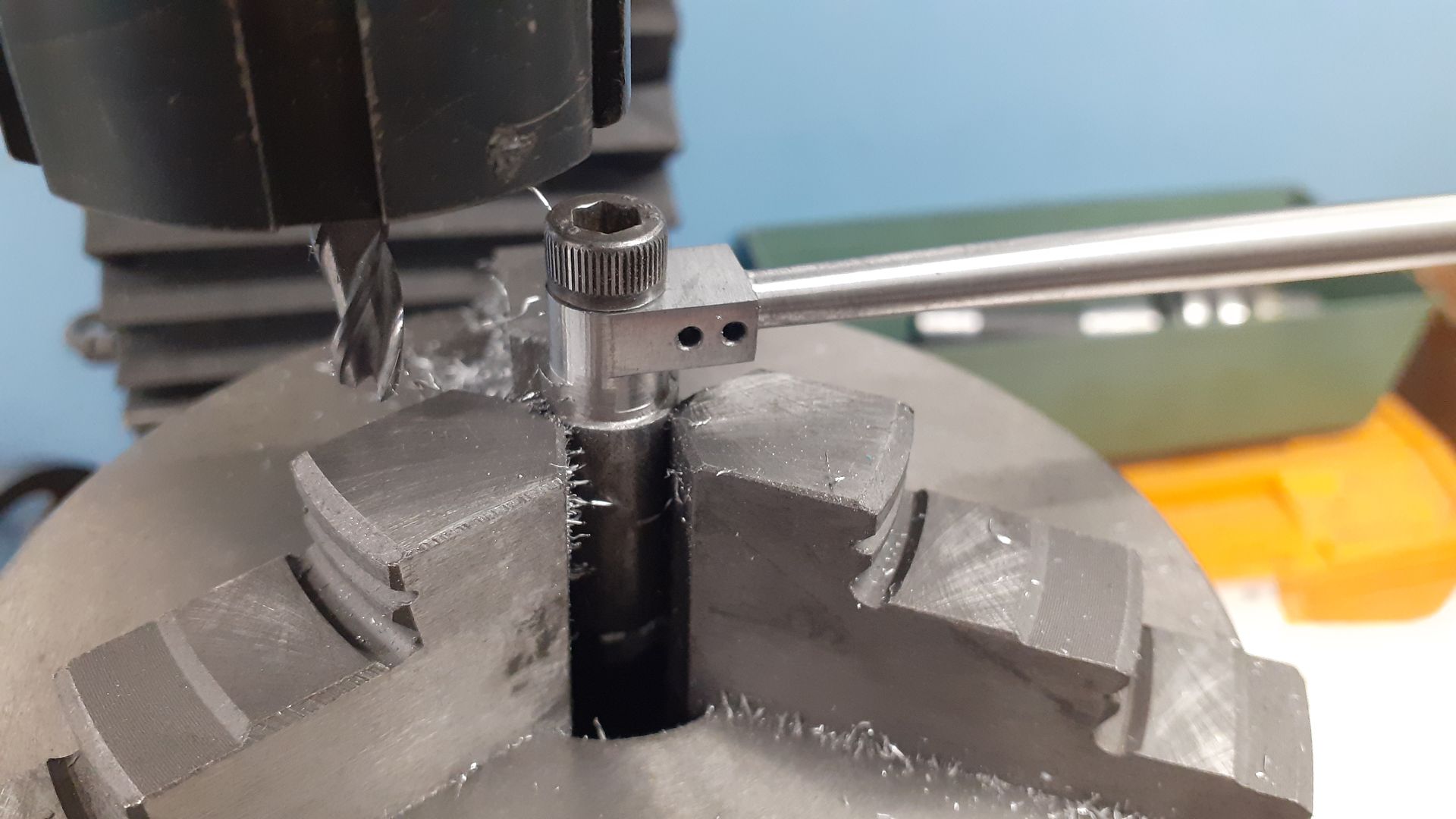
Well I found time to make a start on the conrod part. The marking out and hole drilling went OK then I drilled each end for the centre in the lathe and had a head scratch about supporting it as well as driving it. The consensus seemed to be to use a boring head in the tailstock to avoid cocking up the tailstock offset which takes an age to get back centred, so I got it out and had another ponder. A live centre seemed to be in order so I built one from some bits. I had some 20mm leaded mild steel which turns very nicely so that go bored to 19mm to match some bearings that I had. Pack of ten for 4 GBP from BangGood seemed too good to miss so these have been in the drawer for a few months now. The bearings are 6mm bore so I turned a step on a piece of 8mm silver steel (drill rod in USA they tell me) and put a point on the big end. This looked so good that I got the propane torch out and hardened it, then tempered it in the kitchen oven. This then went in the 8mm collet on the Deckel grinder and I finished the point so that it really looked the part. A bit of shoving it all together and off to try it. The (expletive deleted) thing had bent when I hardened it. So back to just a turned point on some 8mm silver steel and it seemed to be good enough.
I managed to drive it by using a piece of aluminium wire through the crank pin hole and poked down into the spindle nose holes for the mounting pins.
I used a pointy tool to rough out the bulk of the material after taking advice, for a change, and a button insert to finish the ends.Conrod taper.jpgConrod turned.jpg
I just need to work out how to hold it on my tiny rotary table to do the ends now. So far the plan is to clamp a parallel to the table alongside the conrod and clamp the conrod to this. Both ends are still full stock size so it should be interchangeable end for end. A shim of aluminium beneath the part should let me mill all the way to the bottom of the thing without hurting anything.
 
If you have a chuck that will fit your rotary table a simple arbor that fits the conrod hole and a screw to hold it there is what I usually go for.

20221203_153750.jpg
 
I have done that small but the other option is the good old "filing buttons"

Just two round discs 3/32"ID and OD to what the end of the rod needs to be 3/16? make them about 1/8" long. I then tend to use the shank of a drill bit to put through the hole and slip one of the buttons either side, retain with a strips of masking tape around the drill bit. You can now file the radius and as the file gets to the buttons it will just roll on them and not cut any more material.
 
I have also just bought the S50 casting kit which looks to be of pretty good quality so far. I have noticed that some finished S50s look to have brass cylinder tops and stuffing box bases on either end the cylinder as opposed to using the cast iron blocks in the kit. I think this looks nicer, but is it better??
 
When originally brought out the S50 had bronze cylinder, chest and covers and these are what you are likely looking at. They have been supplied as iron for along time now so no need to change unless bling is your thing. If you do change then bronze would be better than brass something like SAE660 (C93200)
 
When originally brought out the S50 had bronze cylinder, chest and covers and these are what you are likely looking at. They have been supplied as iron for along time now so no need to change unless bling is your thing. If you do change then bronze would be better than brass something like SAE660 (C93200)
Yes I thought that maybe the case, also agreed bronze would be better...
 

Latest posts

Back
Top