- Joined
- Jun 20, 2015
- Messages
- 88
- Reaction score
- 173
When I wrote previously, I thought you had done this end flange prior to machining the gauge plate base, and crank main bearings. Thus making the gauge plate was a way to translate the bore/flange machining for the cylinder to make the bearing alignment. I didn't appreciate the gauge plate base was simply a way to make a method of clamping the base casting to the right-angled plate.
I feel you missed the point about my Vee-block idea.
The Principle axis of the engine is the Crankshaft. By "Principle", the axis MUST be identified, and secured by machining very early, so most other critical machining can be taken from this axis.
Of course, to permit repeatable setting-up, the underside of your casting had to be machined first. But that is NOT a running / working surface except for a reference to "other machines"etc. when finally mounted.
The Secondary main working axis is the cylinder-bore axis.
Your odd brass and aluminium insert is a little "weird" (in my head) as you set it into a casting, (Not sure how or where it relates to the casting?) then you precisely aligned this to the Quill axis before boring for the cylinder to mate. I am not sure what all this is really doing...? It seems an Imprecisely fitted bar is being precisely aligned, so the imprecision exists in the machining of the casting?
My sequence (Because that's what I was taught in the 1960s when boring cylinder blocks!).
1: Ensure the underside of the base casting is flat with a reasonable alignment to the CAST bearing and cylinder mounting holes. - This is where an appreciation of Datum alignment is required to understand the castings are NOT perfect and often need compromise, if inadequate machining allowance is not provided. The base grinding set-up is where your brass/aluminium bar could help, but scribe lines on the casting work fine for me. I assume the casting is about right, I.E. plus-or-minus 1/8" from where everything should be. "By eye" marks are better than that, so are adequate to decide where the casting is mounted for the flat underside to be ground. - But you have done all that.
2: From the flat base surface, the bearings can be positioned and machined to form the PRIMARY DYNAMIC datum. This is used to mount the base casting on the precisely set-up angle plate. - But with "freedom" to re-position to the Crank-axis.
3: From this datum, the bore can be set: at Exactly the correct distance for the bore axis to be to align with the Primary dynamic datum. I.E. if the bearings were set at 1.457 INCHES above the flat base underside DATUM, then the bore shall be centred EXACTLY at that same dimension. That will centre the bore on the crankshaft axis.
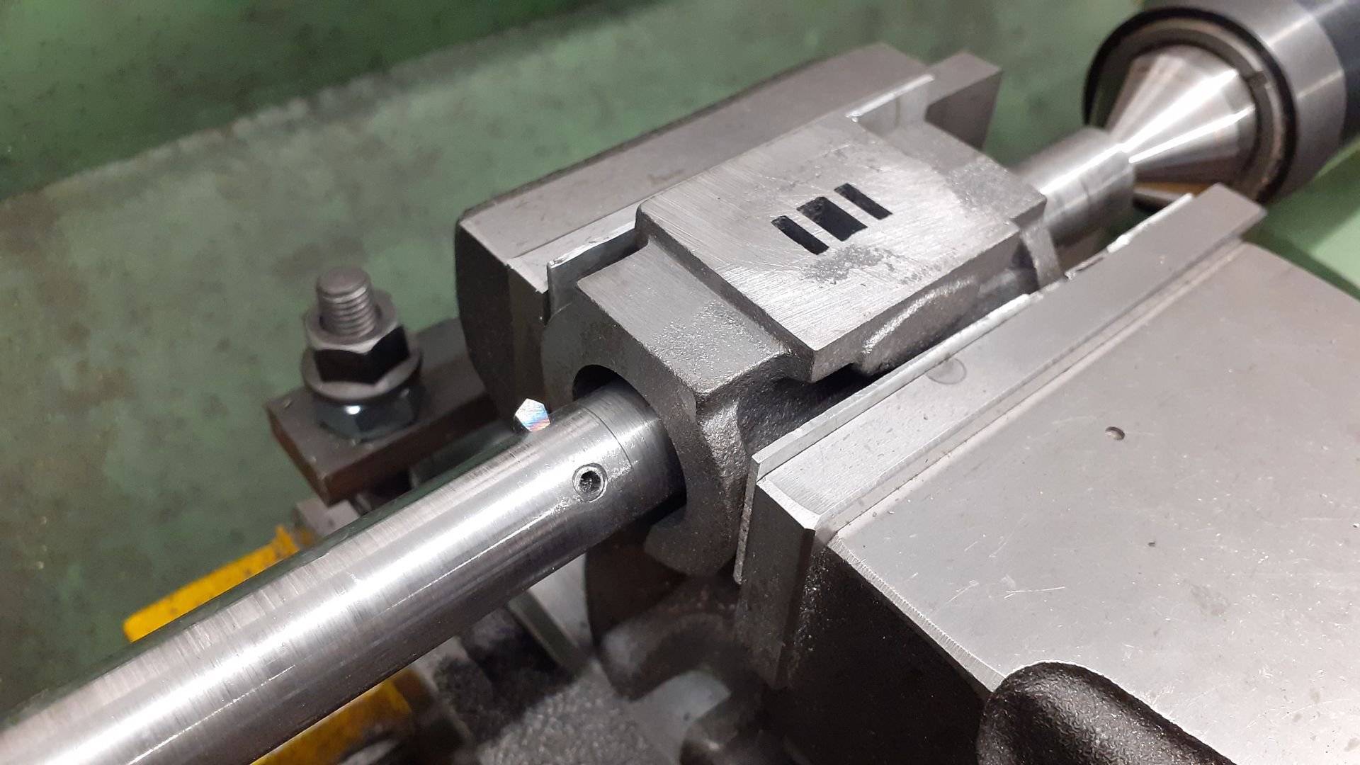
4: With test bar in the bearings, the test bar can be set in Vee-blocks, and the test bar used to clock to ensure it is exactly perpendicular to the Quill. (In case your Vee-blocks are NOT the same size, muck anywhere, imperfect machine alignment, etc.). THEN the base casting can be securely clamped to the right angled plate surface.
You can still use this alignment to eliminate all the TINY errors that are in-built from the machining of all the components by using this as the set-up for BORING the cylinder. All the other stuff is holding the parts together. This BORING to be perpendicular to the crank axis is the PRECISION that makes a good engine.
Sorry if my explanation is a bit crude - Boring even?
If I am wrong will any experts tell me where I am wrong, as I appreciate life-long toolmakers know best - and my friend and mentor is unfortunately past-it now.
j is doing a really careful job, being precise in setting everything to DTIs, etc. But I "worry" that following the wrong sequence or datum can lead to an "Imprecise" engine that disappoints - and we all want this to be the best he can make.
All is not lost: The final boring to the crank axis is the key.
K2
My brass bar was used to ensure that the casting was reasonably straight and that the middle of the journals was in alignment with the center of the cylinder flange. Obviously from a casting it can never be exact but there is little room for plus-or-minus 1/8" on these castings. Not in the middle of the flange webs will see catastrophic results when the flange is bored through.
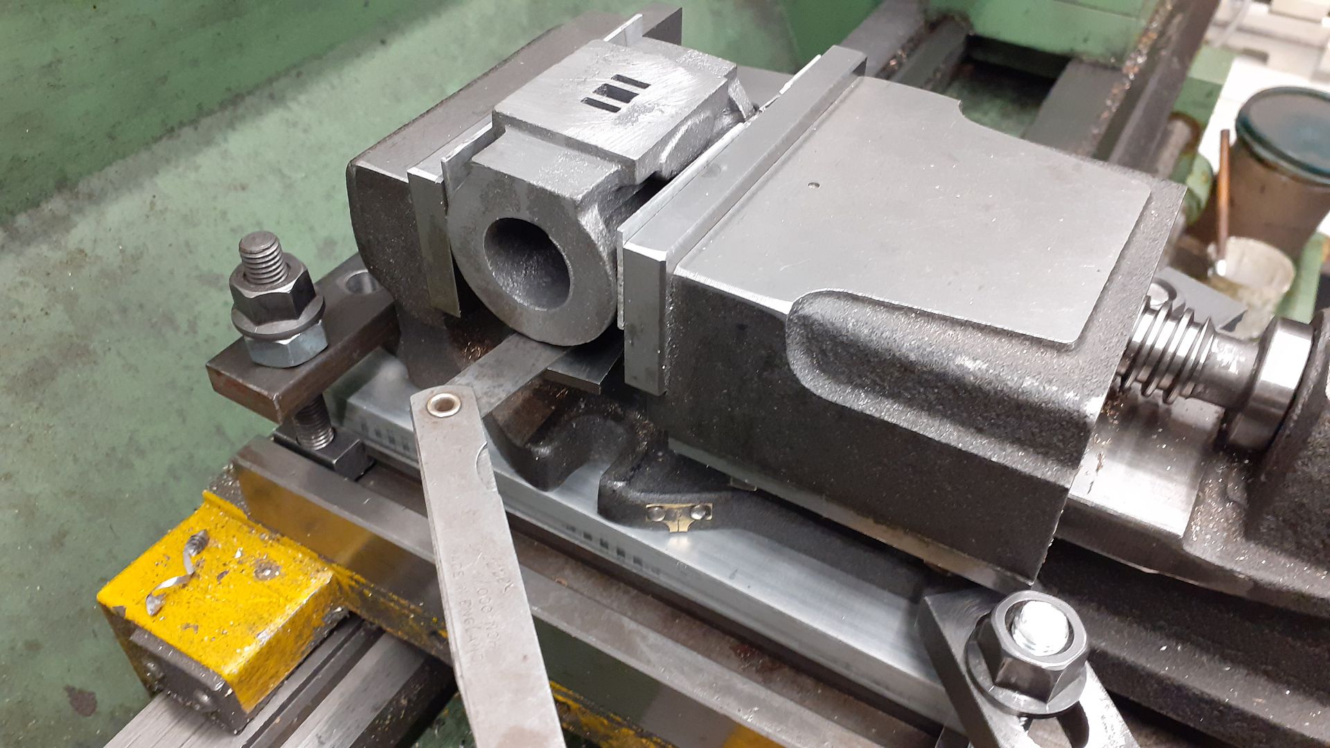
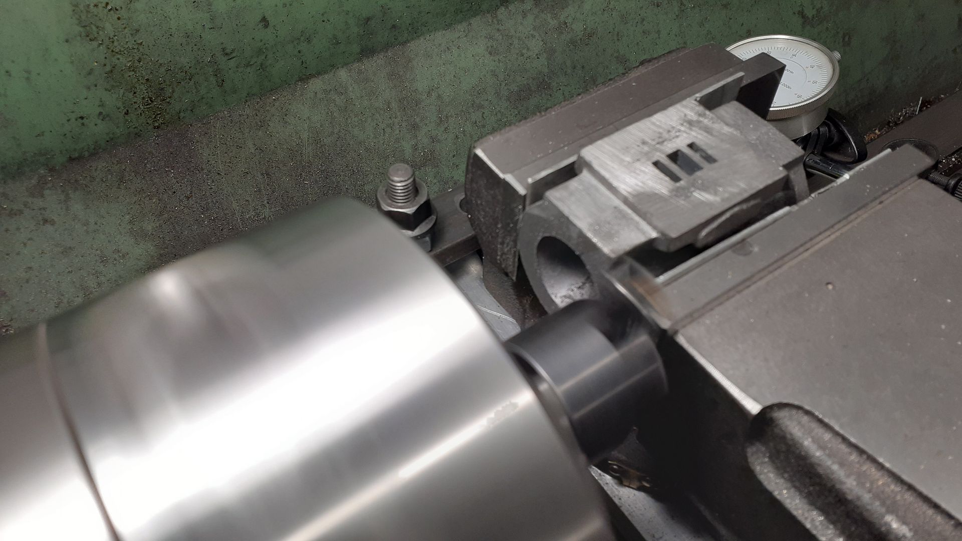
Now that my fixture plate is securely in place all parts will be machined with reference to the primary datum which is the edge of the plate closest to the bearings. I can't use v-blocks until the bearings are fitted and bored. Granted I could have waited until then until machining the flange but that ship has sailed now and had sailed long before you made your suggestion.
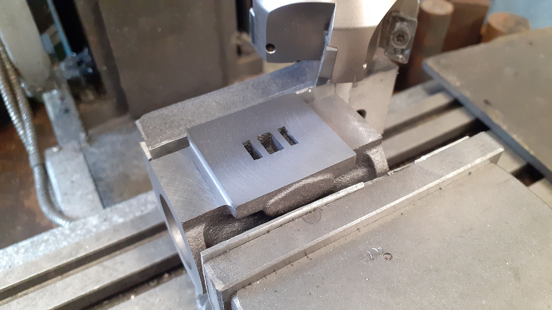
As you say, I could easily grind the flange face using v-blocks and an angle plate if things do not go well. That is always an option. With a bit of luck my bearings will be aligned with my reference and that won't be a problem.
There are many ways to skin a cat precisely.


![20240611_095126[1].jpg 20240611_095126[1].jpg](https://cdn.imagearchive.com/homemodelenginemachinist/data/attach/110/110869-20240611-095126-1-.jpg)


