Some people build Models, others build CNC PLASMA machines

Home Model Engine Machinist Forum

Help Support Home Model Engine Machinist Forum:

This site may earn a commission from merchant affiliate links, including eBay, Amazon, and others.
Rob - can't see if this was covered in your prior posts. If so just say and I'll re read in detail. For the plasma torch, is it using a pilot arc or HF start? Asking as my little 40amp job is HF and wanted to know if cnc for it on the future was viable or not. I would be looking at a SMALL table, 1m x 1m max size. But not sure if viable with HF start. Hence the question to draw on your experiences.

Cheers,
J.

James, I have this one with a built in CNC port.
http://www.everlast-welders.com.au/product/PowerPlasma_50.
It has a blowback start. They say the Mesa THCAD can handle HF start. I think HF start might be hard to control noise and may need an earth stake driven through the slab. I think getting up to a 24 volt vs 5 volt system will help fight noise but I have not fought that battle yet.

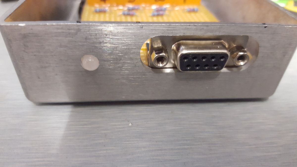
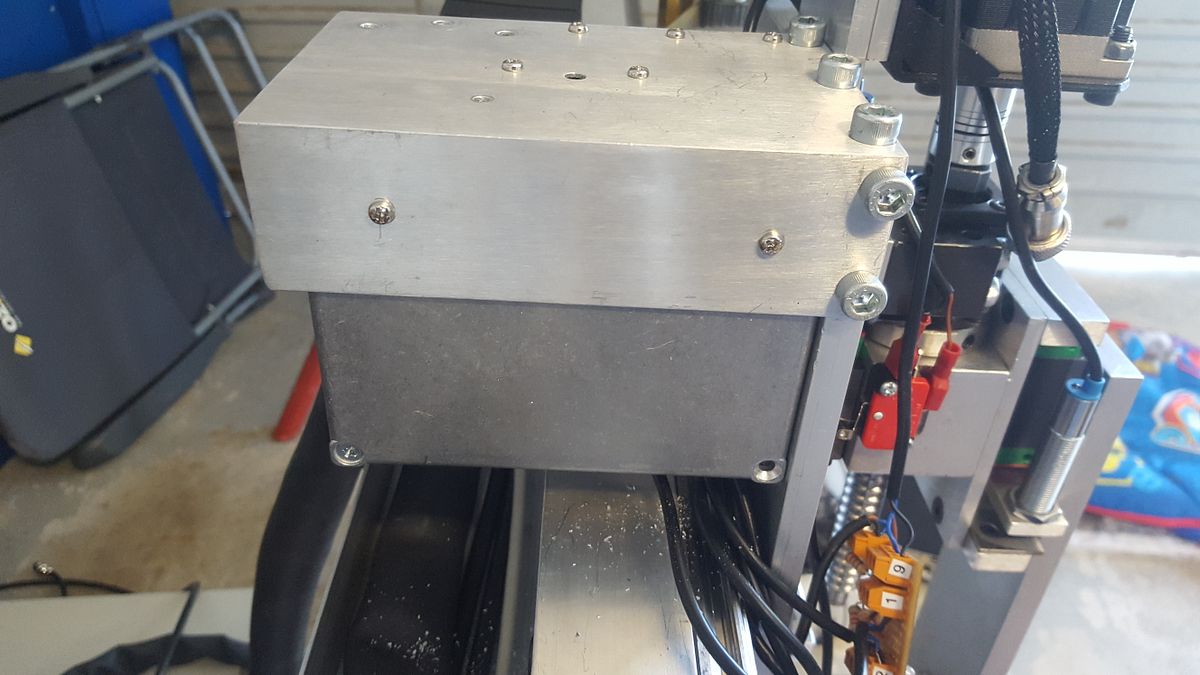
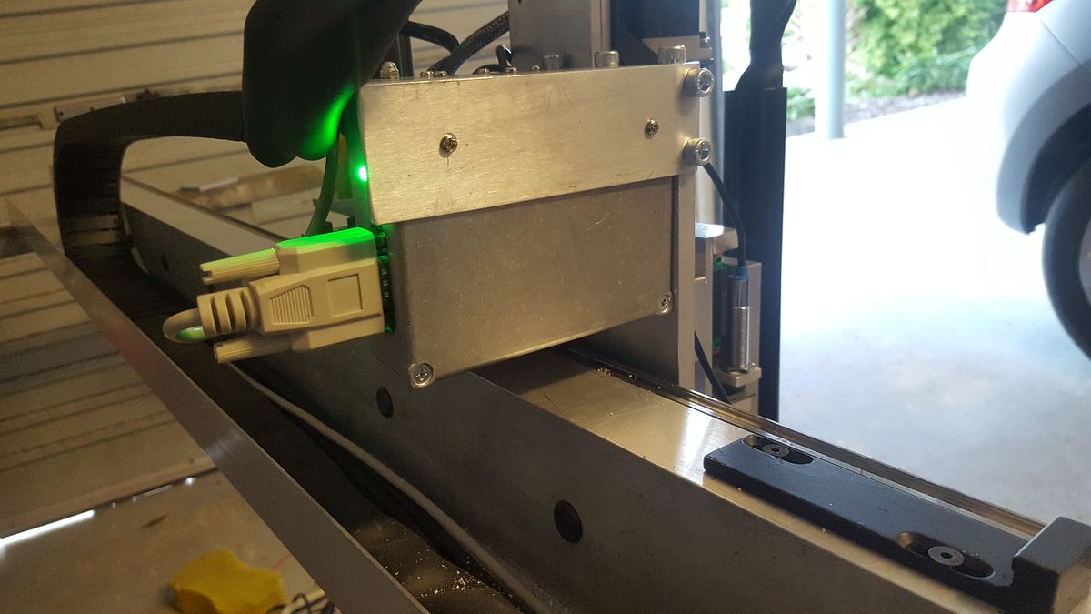
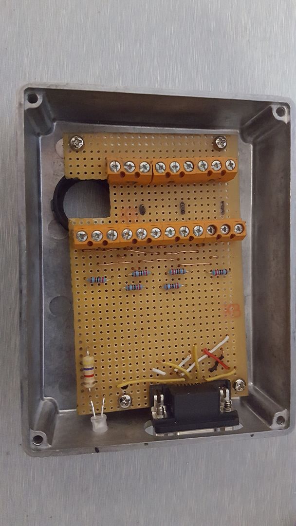
I spent all of today rebuilding the bent circuit board and mounting it a bit differently (in a metal electronics enclosure).

20170409_155635_zpszpp5ohpp.jpg


its so nice to have a mill when you are doing something like this

20170409_155654_001_zps2mupd8gp.jpg


Looks like its going to work out OK

20170409_162057_zpscysgadap.jpg


And all mounted up

20170409_170758_zpsvcu7ha3x.jpg


THe LED is just a warning light to say I have 24 volts up there for trouble shooting. It has told me about one problem already..

I am still not sure if this has fixed my problem as I did not have much time by the time I got this done.
 
Looking good.

The only thing I would be paying attention to is the level of side forces on that plug. Given the only strength, from what I can see, was from the soldered mounting pins. If you don't already have it a strain relief clamp might be an idea?

Cheers,
J.
 
Looking good.

The only thing I would be paying attention to is the level of side forces on that plug. Given the only strength, from what I can see, was from the soldered mounting pins. If you don't already have it a strain relief clamp might be an idea?

Cheers,
J.

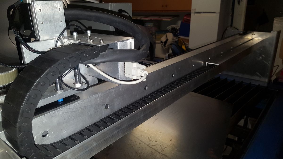
I'll give that a bit of thought. THere is not really any side forces as the DB9 cable is held firm where it exits the drag chain.
 
I'll give that a bit of thought. THere is not really any side forces as the DB9 cable is held firm where it exits the drag chain.

Ok - probably not going to be an issue then. :thumbup:
 
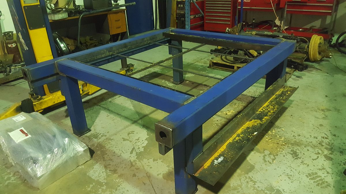
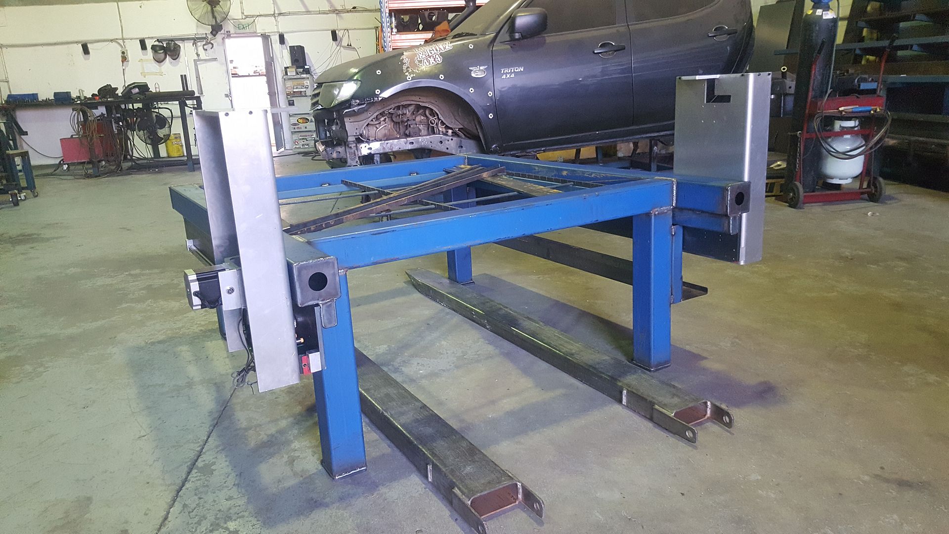
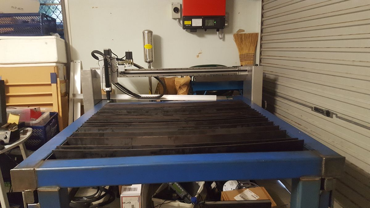
So i've now got a table!

20170412_173953_zpszxureflo.jpg


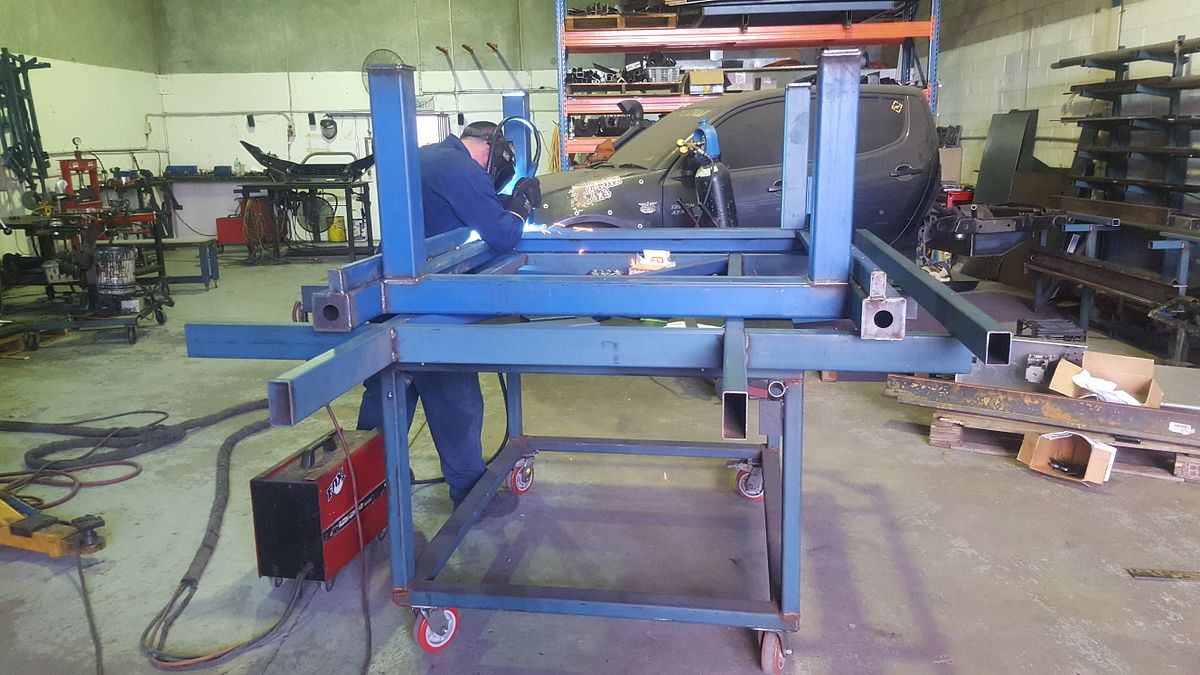
And here's why I didn't bother to weld up such a precision weldment..

20170412_155504_zps2aehhovn.jpg


Nice Work from Lee

20170412_163511_001_zpsncl4nrt0.jpg
 
Very nice. Is that TIG or MIG work? If you tell me he did that with a stinger I am going to find a corner and quietly cry. :hDe:
 
Very nice. Is that TIG or MIG work? If you tell me he did that with a stinger I am going to find a corner and quietly cry. :hDe:

MIG, I'm afraid, his TIG is mint too!

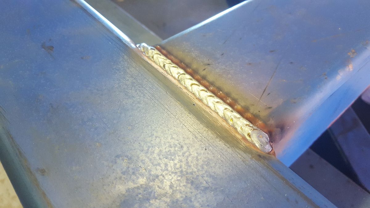
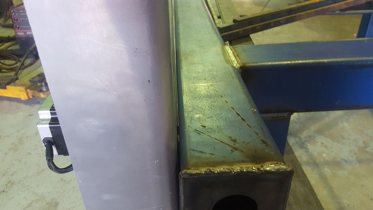
Anyway, to cheer you up, I had a go at him today for putting the one cr@ppy weld on the top of the machine for all to see. Anyway, I put some of it together, and over the weekend, hope to mount up the gantry.

20170413_165646_zpsw0asfeus.jpg


I am happy with the clearance between the gantry ends and the table, but not the weld! Anyway, a brush with a grinder will tidy it up. This is the first he did then he must have dialed himself in!

20170413_165705_zpsnhdax81d.jpg


Hopefully, it will help keep the rails clean tucked so far back.

Its kinda funny, when I was looking at the gantry ends, they looked too long but now they are assembled, they look correct and in proportion.
 
Looking at it in relation to the car ... that's a sodding big lump O steel. :)
 
Looking at it in relation to the car ... that's a sodding big lump O steel. :)

And heavy too! I could lift one end pretty easily before I put the linear rails on. I can just lift one end now but at the end where the gantry is parked, I could not really move it much at all. The rail mounting plates were hard to attach on my own as they are probably about 50 kg each. I figure it will weigh in at around 400 kg when done.

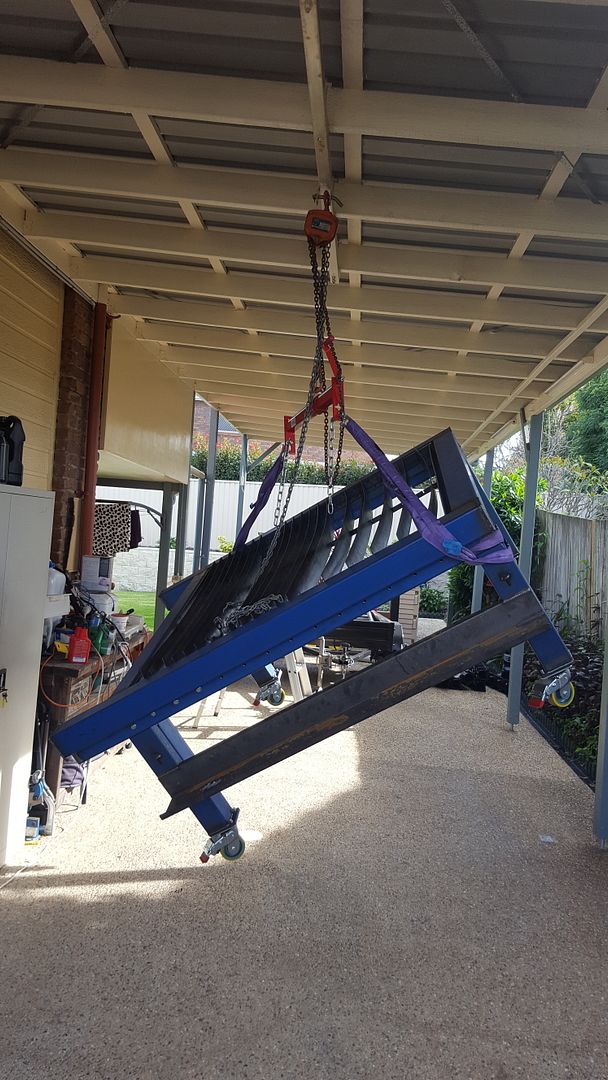
The table is roughly 1800 mm x 1800 mm square and the frame is 100 x 100 x 4mm SHS.
 
Its been a while since I updated this thread. There is 2 reasons for that. One is I stuffed up one of the laser cut parts so I had to get it recut before I could make the cradle that holds the slats. And then I found out that Lee had given me the wrong measurement by not allowing for the 5mm steel sides. I had to cut 5mm off each end and still have not got it welded up.

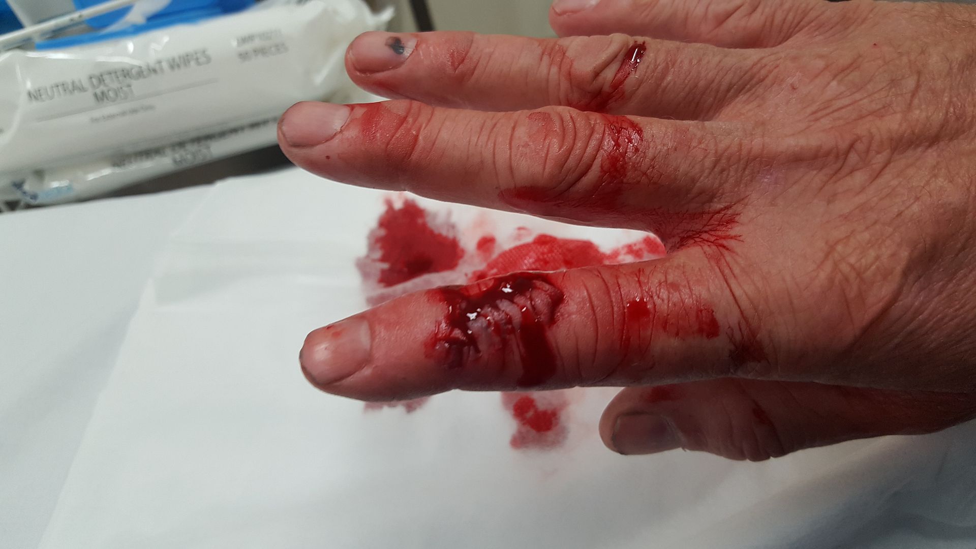
The other reason is I had a small mishap with a milling cutter and a finger on Good Friday.

20170414_143742_zpsno62sw1p.jpg


It was decided this needed to be repaired by a hand surgeon and as I had eaten lunch just before I did this, they waited until 7:00pm before patching me up in theatre. There is a tendon on each side of the finger and fortunately it went between them both which was very fortunate.

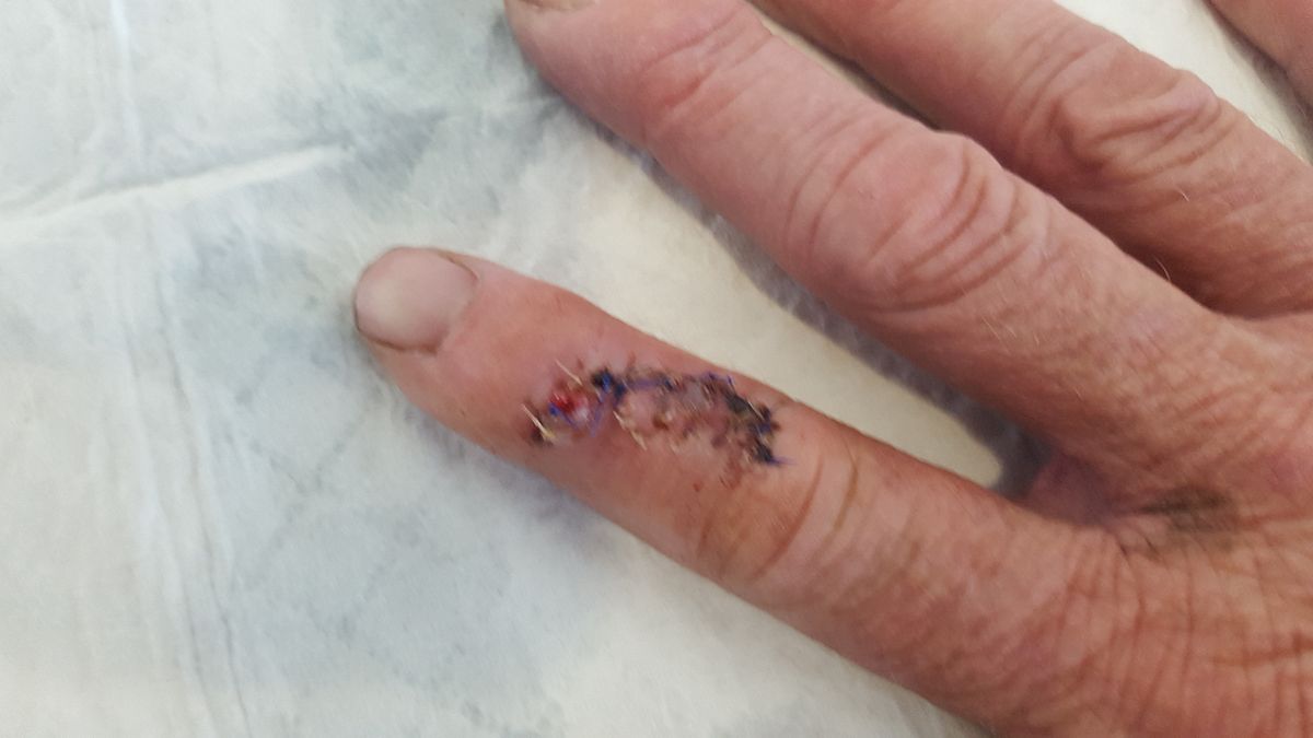
A week later all was well and healing better than the surgeon expected.

20170420_162850_zps2nbk5yty.jpg


Anyway, now it is another week on and I've had the stitches out (about 20 of them not counting the ones that dissolve) and its starting to come good.

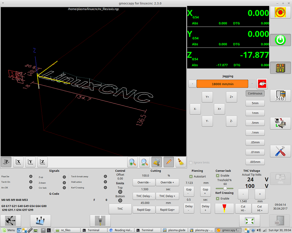
I tried to be good by not going into the shed so that left me with the software to work on. So after about 2 weeks, I think I have finally finished the screen interface and connected up all of the signals in the back end.

Screenshot%20at%202017-04-30%20090414_zpsxk4iyi2n.png


As I read somewhere, Plasma cutting is really an orphan in the CNC world as its so different to a mill or a lathe. That is because the Z axis is controlled outside of the typical XYZ kinematics model.

I had a starting point for the screen from a LCNC example, but all of the stuff below the screen preview I have pretty much written.

During this process, I also purchased Sheetcam which is really brilliant for post-processing DXF or SVG files into gcode. It also has nesting capability to fit multiple parts on one sheet of material. With some help from the LCNC forum team, we've modified a GUI interface and added some other components written in C to allow us to use a Sheetcam post processor that has been written to support a commercial torch height control unit.

I have to say this is right on the bleeding edge of LinuxCNC development because one of the main developers has built an experimental branch that integrates external offsets into the core code. What this means is you can apply an offset that is totally transparent to the LCNC trajectory planner. He clearly had plasma in his sights as he also wrote a component that was aimed at plasma torch height control and built in PID based control along the same lines they do to control servos.

I've written five LCNC support components that allows me to hook up all of the GUI to his experimental torch height control component. I finally solved the problem of accessing the GUI settings from within gcode last night.

A component in LCNC speak is a small snippet of compiled C code that is called on every pass through a thread. With my hardware, that happens 1000 times a second. You connect various inputs via "pins" in a "hal" text file. "hal" stands for "hardware abstraction layer". This really is a pretty cool software development model as everything remains modular. So for example if your component needs to know the current velocity the plasma torch is travelling at, you provide an INput pin for current velocity and connect the system pin motion.current-vel to it in the hal file.

So from the screen dump, you can see there is about 12 LED lights to tell you what is going on and several parameters that can be changed by the user at the touch of a button on the (yet to be purchased) touch screen. I've actually run out of screen real estate and would like to add a few more controls so I might end up adding a tab in the interface so I can add a few more controls.

Anyway, with a complete GUI and software config, an almost complete table, and a fully configured Sheetcam post processor, it won't be long before this all comes together into a working machine.

Today marks 10 months since I started this project so hopefully, it will be done by the 12 month anniversary.
 
Its been a while since I updated this build. My finger came good and I brought the fabricated plasma table home so I could keep working on it as it would never happen at work.

20170513_094821_zpsry1ifyab.jpg


And I married up the gantry but it still needs all of the stays fitted to secure the gantry to the gantry ends and I have to wire in the limit switches in place before I can actually do much with it.

20170513_170559_zpsavb99qvq.jpg


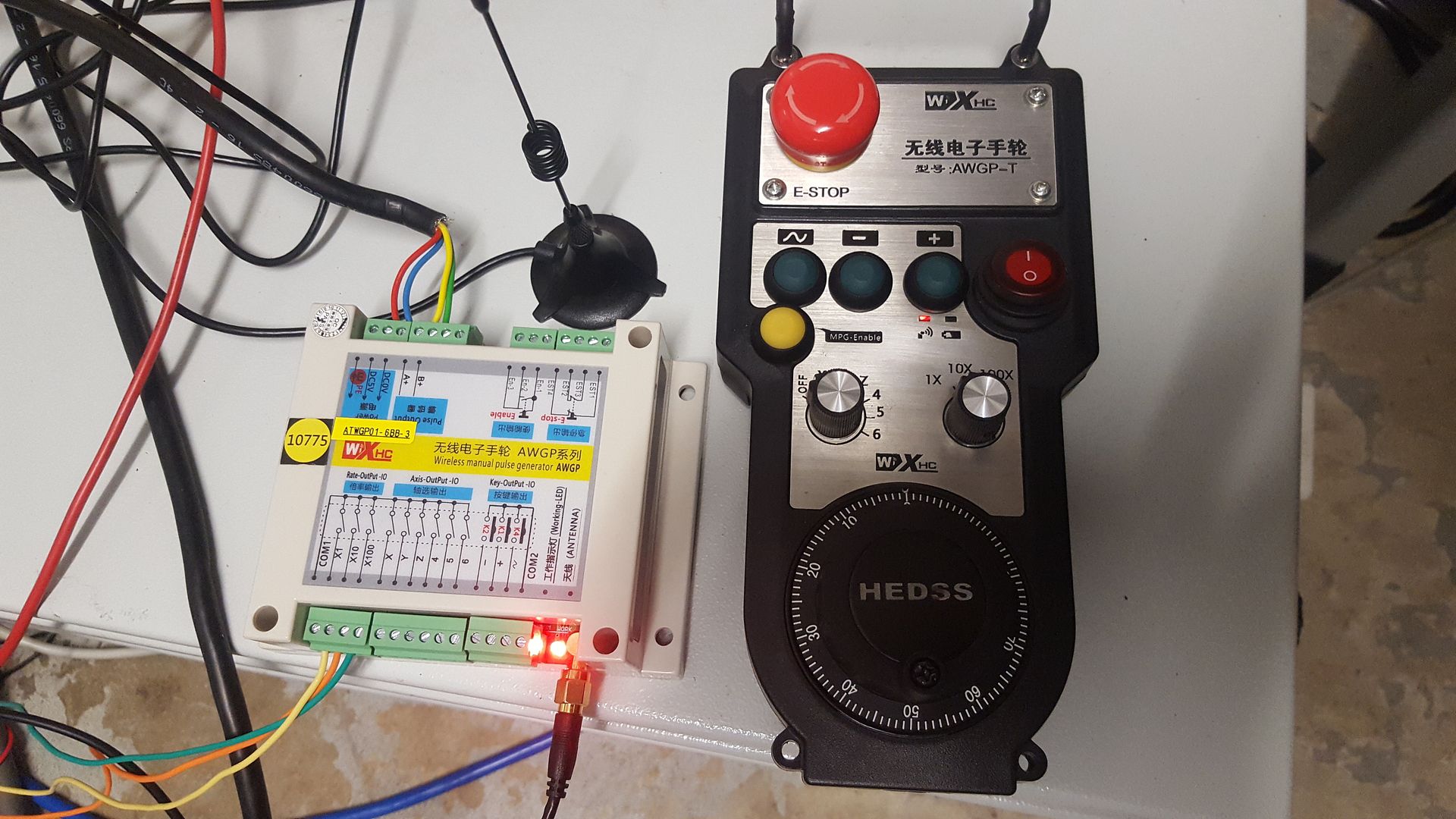
I bought a very nice wireless remote out of China

20170512_222318_zpsy5k3ikco.jpg


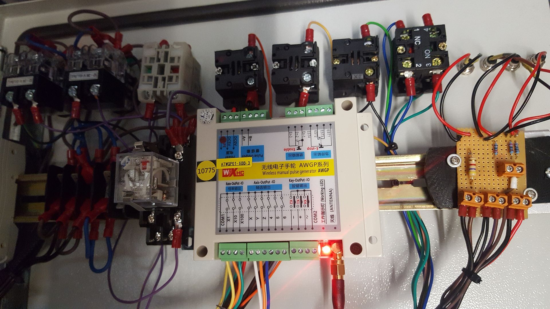
And yesterday I pretty much got it all wired up. THis required quite a bit of reworking of the estop circuits but I think I got it pretty right after yesterdays effort. Sorting out the configuration file took a bit of experimentation as I had no examples of exactly what I wanted to do but I worked it out in the end.

20170514_124957_zpsdmgrtban.jpg


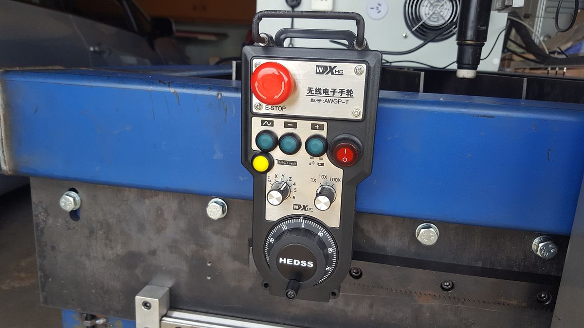
The pendant has some nice magnetic mounts to store it.

20170514_124019_zps5v7utf4l.jpg


This ended up being a perfect match for my hardware but it took a night messaging China to make sure I had the specs right.

20170521_134702_zpsfju7tq0w.jpg


Time has been at a premium and I have not been well so I've been avoiding the physical stuff and just doing the wiring and software config. I still have bit of tidying up of the wiring as there is still quite a bit of test wiring there that will be removed eventually.
 
Rod,

That's shaping up quite well. I'm following and I hope to see a video of it running someday. Thanks for posting the electronics and programming as well as the mechanics of the build.
I wish you happy healing and I understand as I got myself almost the same finger injury last week and am out of the shop for awhile myself.

Good Luck,

--ShopShoe
 
Its been a while sionce I've done much on this project. 2 more triips to hospital after cutting my finger did not help.

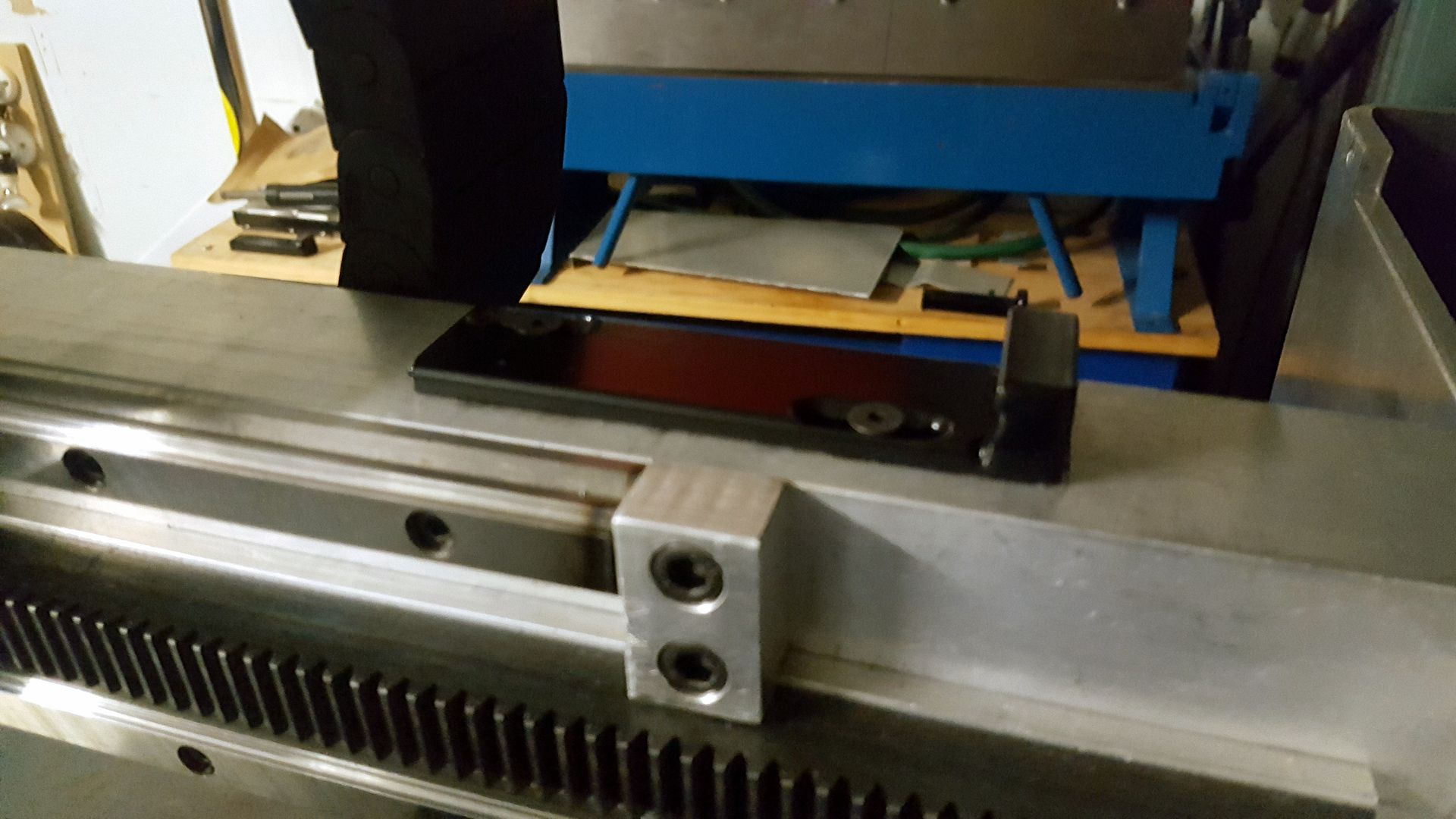
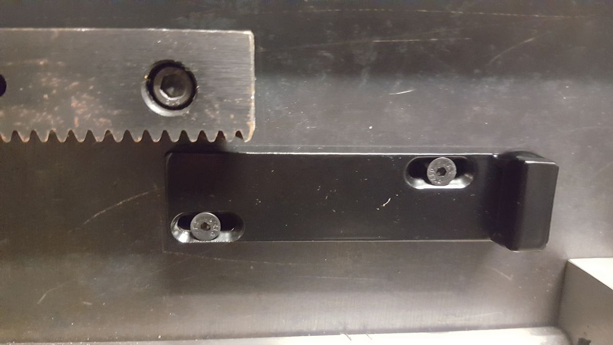
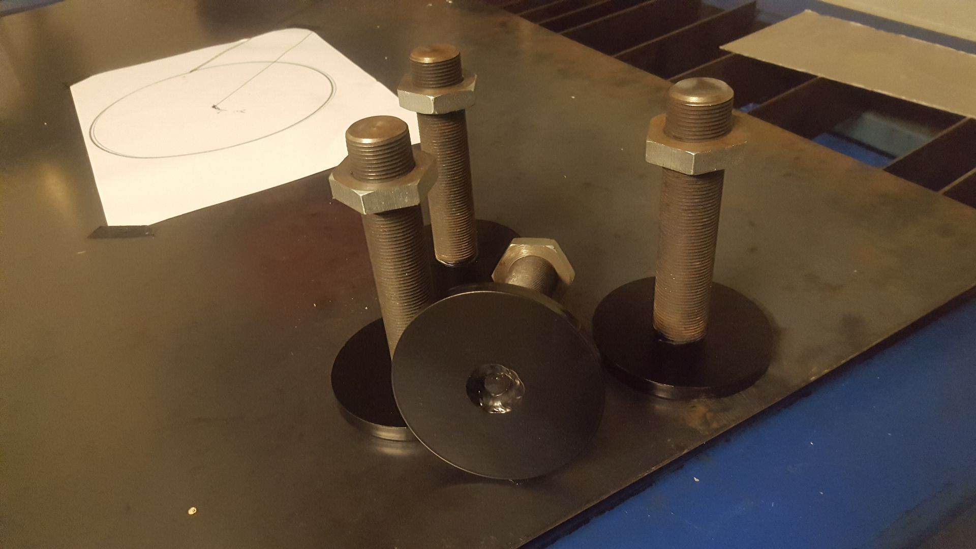
I ahd a few parts getting powder coated so I sent out my limit switch plates and the levelling feet.

20170624_202733_zps0xxelreg.jpg


20170624_202837_zpsfsaqwscw.jpg


20170629_181400_zpsldmafzf7.jpg


And I tidied up the drag chain support tray

20170624_202633_zpsfeeloz3a.jpg


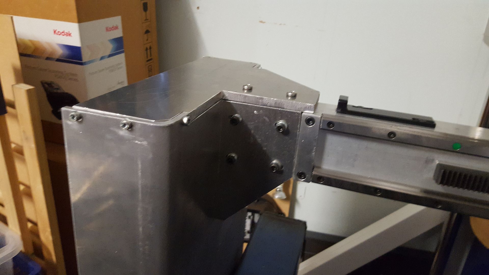
And I braced up the gantry ends

20170625_170140_zpsiyx8wqzd.jpg


20170625_170213_zpskshrd97s.jpg


This one was a bit trickier to squeeze in
20170625_170232_zpsto91frtp.jpg


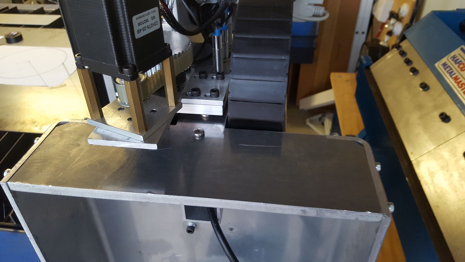
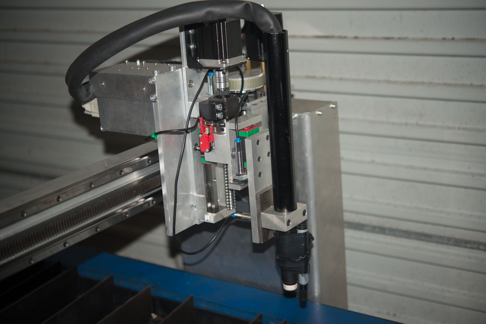
And I shortened the Z axis to get more travel.

DSC_7479_zpsytksv5vk.jpg


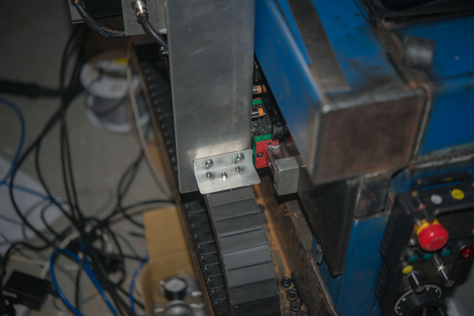
And started to work on the drag chain

DSC_7484_zps5dqc6jj5.jpg


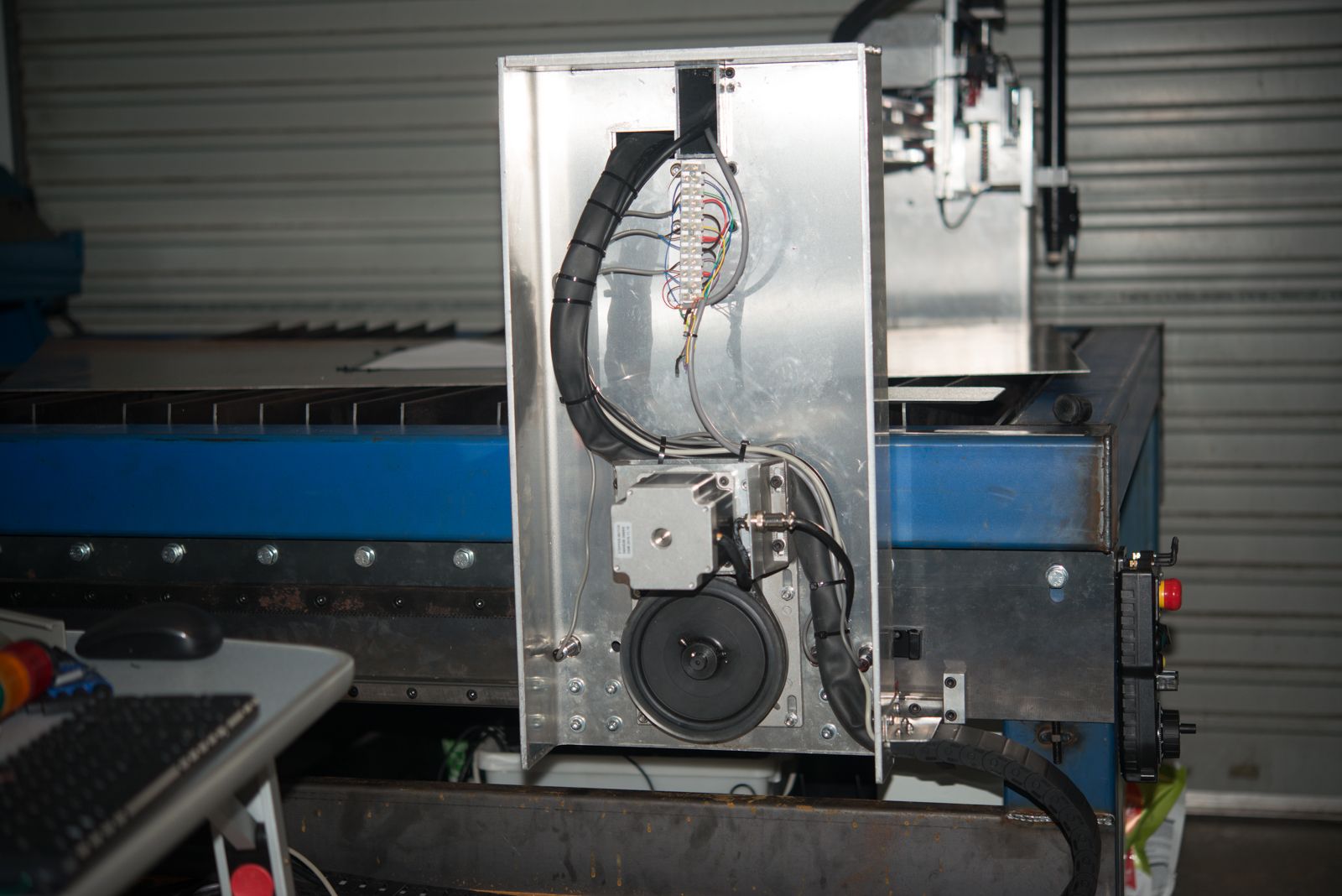
And get all the wires across to both sides of the gantry and attached to the limit switches

DSC_7476_zpsbzfwnsna.jpg


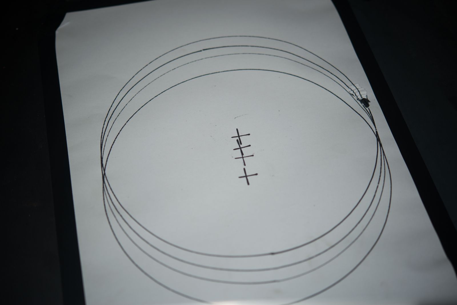
And finally, taped a pen onto the torch and drew something!
DSC_7481_zpsncwozeht.jpg


Then pen was wobbling around a bit but I am happy with the accuracy.

I also put a dial indicator against one of the gantry ends before I had it all properly braced and was only seeing about 0.05 mm play under acceleration of 1 m/sec/sec so it is well within the 0.1mm I accuracy I was hoping to achieve.

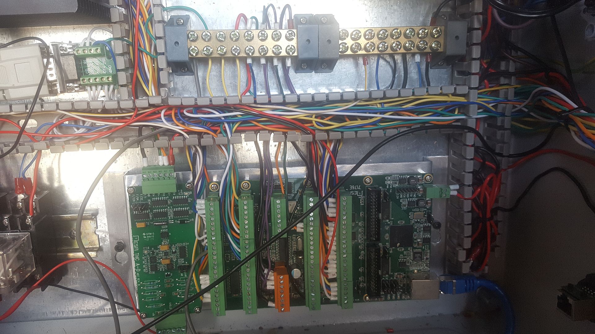
I ran out of time but all I have left to do is to connect the limit switches and sensors to the Mesa control board and sort out the calibration and config. This will let me home the machine and square the gantry so then I might even be able to cut something!

I also have plenty to do to fit up all of the connectors to the control box as I have not wanted to do this until I knew I had a clear idea of all of the connectors required.
 
Well it been 12 months since I bought my first part but this machine is nearly done. I'm really happy to actually see this machine running Gcode (at 18 metres per minute - 709 inches per minute). I've tested it without missed steps at 21 metres per minute (827 IPM) but I thought it might not be a bad idea to back off a bit.

https://youtu.be/h_7S6iN6-AE

Now its moving, I've spent a fair bit of time debugging and double checking HAL and .INI files. I've done as much testing as I can without cutting stuff. But before I can do that I will have to make sure that I have a Sheetcam post processor that works.

I did find out why people use Ohmic sensing. Here is some 2mm plate during a mock touch off and you can see the plate springing down before the probe triggers and follow the torch up.

https://youtu.be/astf0jqtMrU

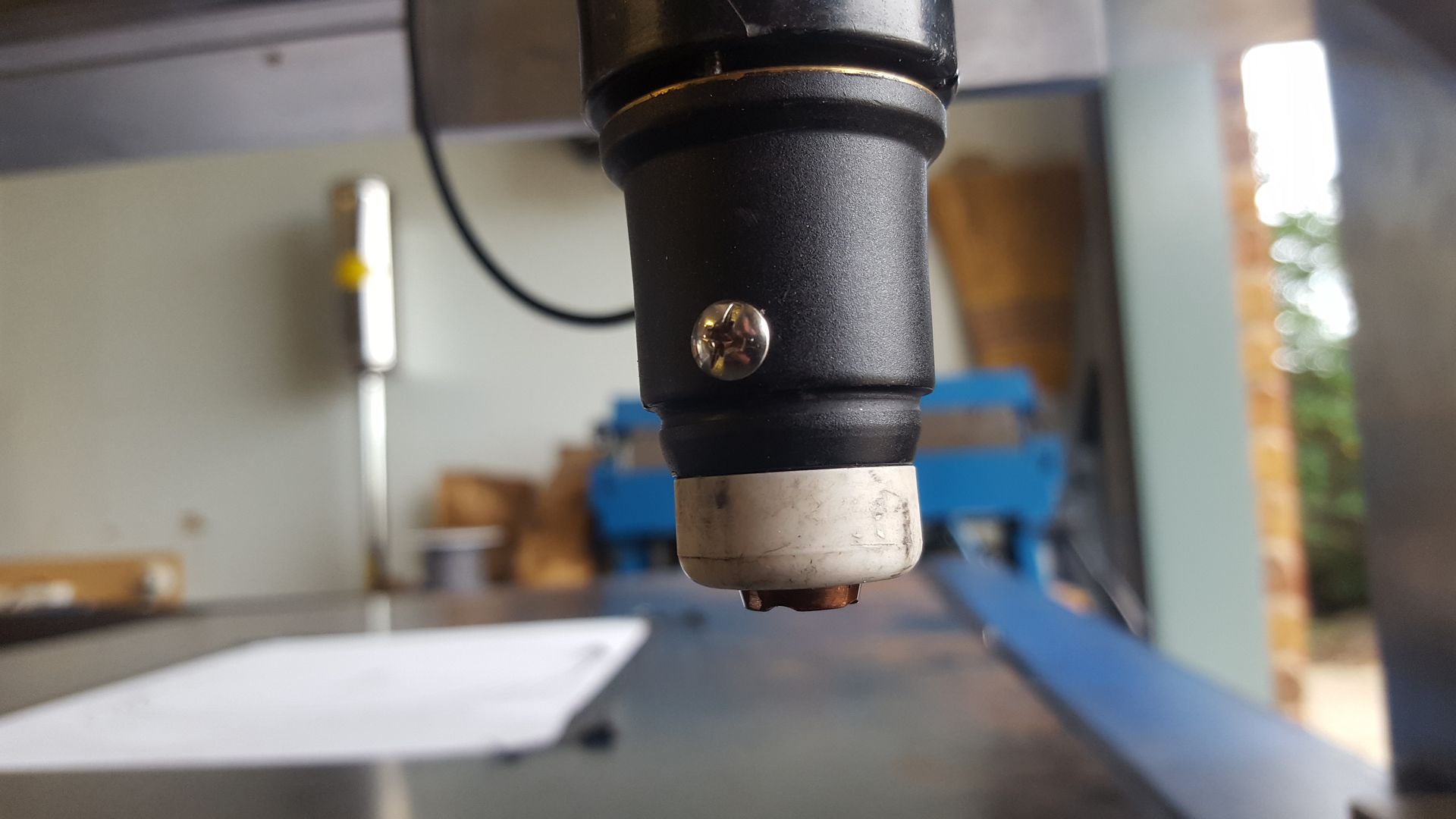
My Trafimet torch does not have provision for an ohmic sensor so I drilled and tapped the cup so I can attach a wire as there is now an electrical connection between the screw and the tip.

20170709_154814_001_zpsnzjetrwz.jpg


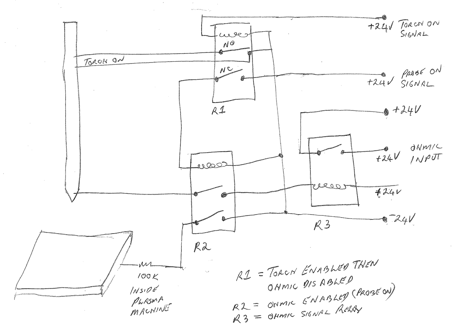
My torch has a connection to the earth clamp on the plasma in the CNC port and previously I found a relay circuit for a sensing circuit which I've modified a bit so there are a couple of safety interlocks.

OHMIC%20SENSOR%20CIRCUIT_zpss7bildad.png


So I bought a couple of relays today so I can build this circuit. I am sure the questions will begin now I've got this far and here is the first one.

I think the bottom two 24 volt lines that go to the workpiece and the torch should be from an isolated power supply so there is no chance of blowing up my Mesa 7i76e control card. What is the cheapest and/or best way to to do this? WIll a simple buck power supply off the 48 volt rail do the job or should I get a small DIN rail power supply?
 
Rod,

You have more experience than me, and my electrical/electronic experience is really old-fashioned (relays I can understand.....), but work-a-day functional.

It would seem that a totally separate power supply would remove all doubt as to whether there is interaction between different parts of the system and would do a better job of keeping the other parts of the system safe from damage. As we used to say building it ruggedly to start and then optimizing it later got things running faster than agonizing over the details endlessly at the beginning.

I am also a great fan of modular design of all types, so having separate modules like power supplies to swap out make changes and repairs easier.

I ramble... I am enjoying this build and thank you again for posting.

--ShopShoe
 
great build, keep the pics coming :thumbup:

may of been answered before....but. is the workpiece earthed from the machine? i ask as my mates plasma has an earth clamp that clamps to the work and when the torch touches the work all hell brakes loose.
stepper motors are earthed to the table. if you have a touch prob, that will earth to the table on contact. plus the torch will need to earth to find its height. so in my tiny little brain, i sort of think that as soon as the torch lights it will send all the amps/volts and power through everything.

Blighty, thanks for the encouragement. Yes I was really hoping I would not need to build the electronic sensor. It is a bit scary when there is 300 volts floating around.

I think it should be OK as long as the sensing circuit is disconnected while the torch is cutting. The first precaution is to use a totally separate (isolated) 12 volt power supply for the sensing circuit.

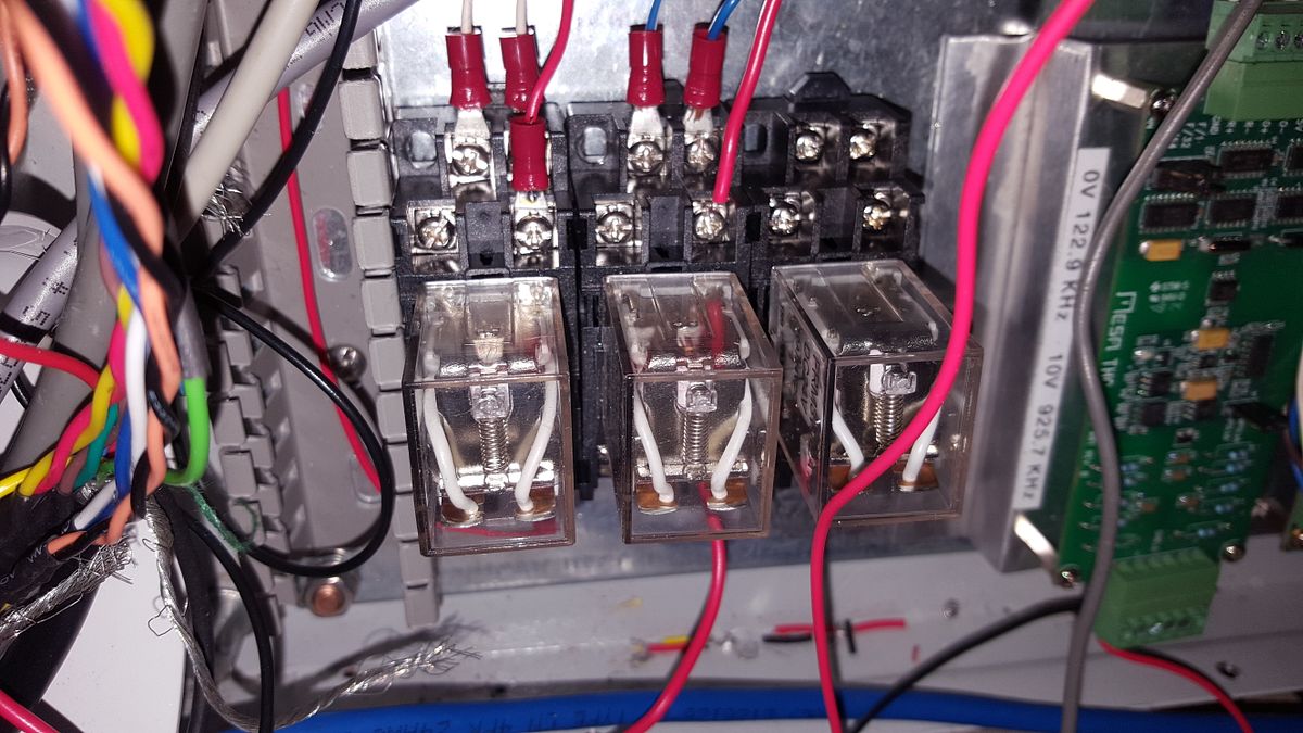
I am also using some panel relays to do various things. These are all double pole double terminal ones.

20170711_193120_zpsxadqr9jp.jpg


So the relay on the left is the one that turns on the plasma torch. So the second safety precaution is to run the signal through the other side of this relay using the normally closed connections. So when the torch is on, the sensing circuit has to be off.

Then the next step is to tie an output pin to M64 and M65 in the gcode I run. These codes allow me to turn a digital signal on and off. So there is another safety relay (the one on the right). I will call M64 whenever I probe to find the surface. This will trigger the rightmost relay which will connect the wires to the sensing wires on the table and the work piece. After the probing has found the surface, I will call M65 to turn the relay off again.

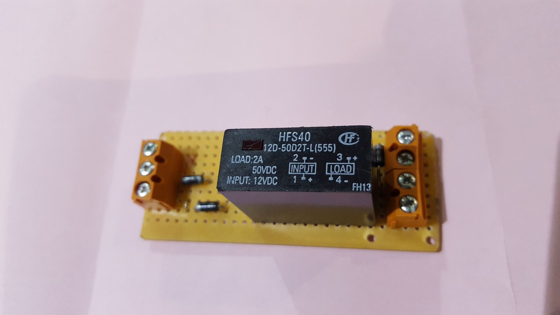
Finally, I decided to use a solid state relay that I had floating around and I mounted it onto a circuit board tonight with a few other components.

20170711_192434_zpsapgxlv6t.jpg


Its purpose is to use the new isolated power supply to trigger the relay when the torch touches the plate. This relay will then switch my +24v power to a digital input that will tell the machine I have found the surface.

There are several 1N4001 (1000 volt) blocking diodes on this board. Diodes only allow current to pass in one direction.

So here we are a bit tricky. On a plasma machine the earth clamp is actually positive and in our sensing circuit it will be negative. So if for some crazy reason the torch is running while the probe is enabled, the diodes should prevent the current from passing and destroying anything. Hopefully if it does get that far, it will only destroy the few components on the isolated power supply and not a $500 control board!
 
thanks for you explanation. but i still don't get it. my brain still thinks you going to send all the electron stuff through everything. don't get me wrong, im not saying what you have done wont work, as lots of people have done what you have done and end up with a perfect working cutter. so until i get me head around it, i wont get it.
it's like i could never get my head around how they made tooth picks. i thought the only way they could make them was to get a bit of wood. put it in a lathe and turn it down to toothpick size...... was i surprised
when i saw How It's Made one night.

also.... reasone for clearing this up. is i have a tig welder and one job was a seem weld over 24" no filler and had a few to do. thought i could put the torch on the head of the mill, work on the bed etc etc. but didn't do it because as soon as i push the button 150amps would be going through everything................... come to think about it. i could of put some MDF on the table. oh well live and learn.
 

Latest posts

Back
Top