- Joined
- Oct 28, 2009
- Messages
- 58
- Reaction score
- 36
I've begun building Bob Shores' Silver Bullet from castings I bought 15 years ago.
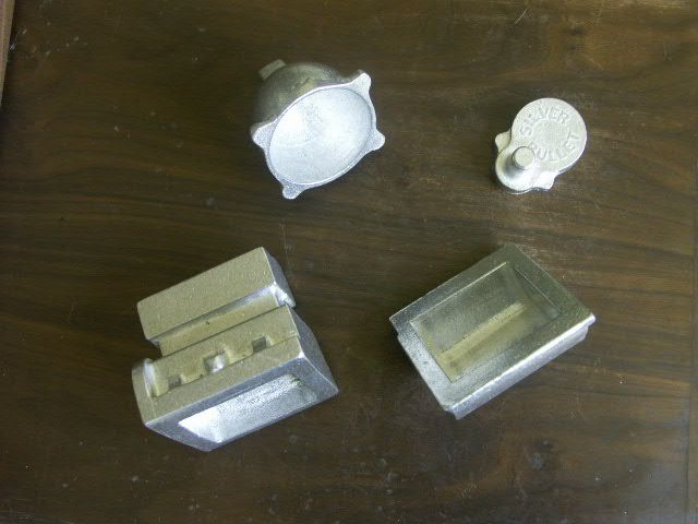
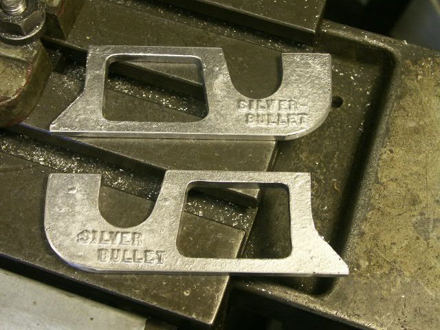
My kit didn't include the engine stands, but a friend made castings using the ones from his kit. Thanks, Birk!
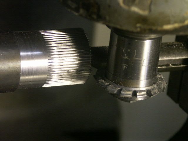
I decided to start with the gears, since I had never made any before, after about 30 years in this hobby. A friend offered to let me borrow his brand new gear form milling cutters. What a treat! Thanks, Richard! But I was nervous every minute that they were in my possession so I got right to work on the 64 tooth gear.
I made enough for three gears, and then parted them off.
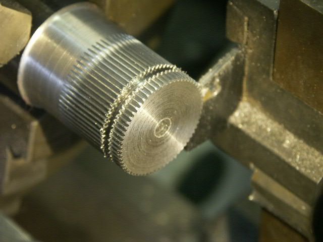
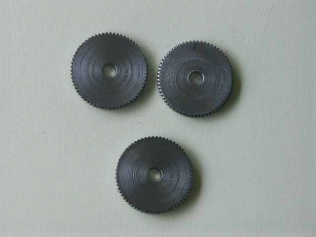
I then did the same with the 32 tooth gear. And returned the cutters ASAP.
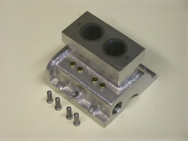
It looked like the cylinder head was one of the more complex parts, so I started it next.
I squared up the block, and drilled the through holes for the coolant and cam shaft.
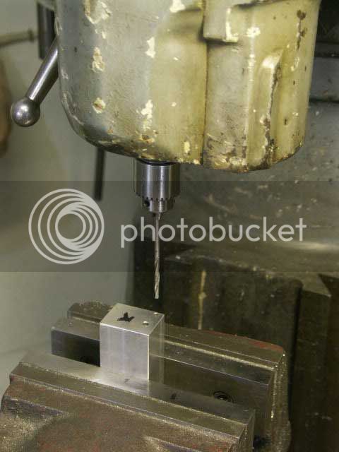
drilled and reamed the holes for the valve guides,
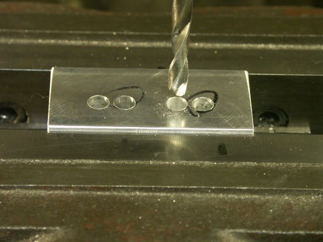
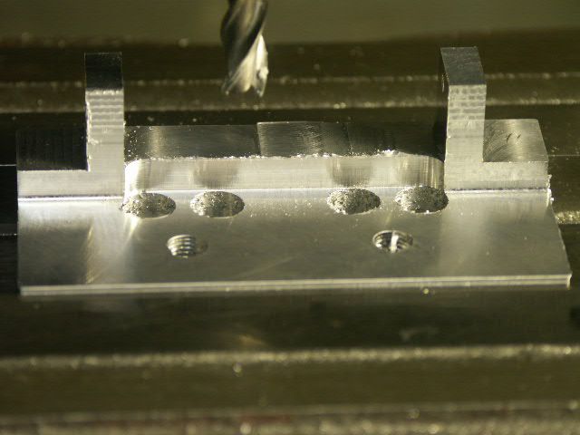
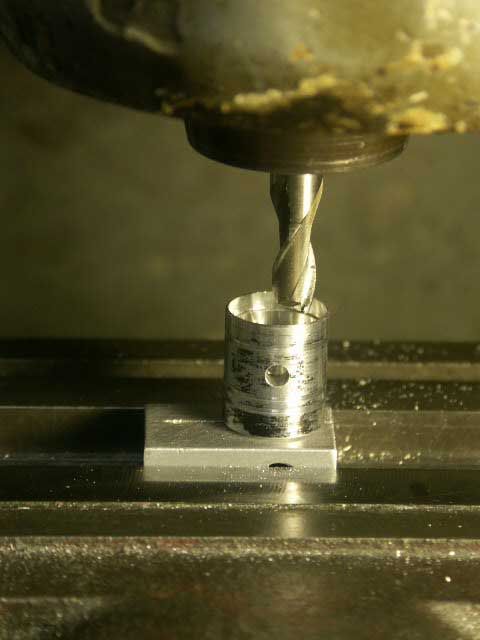
and milled the combustion chambers with a .750" end mill.
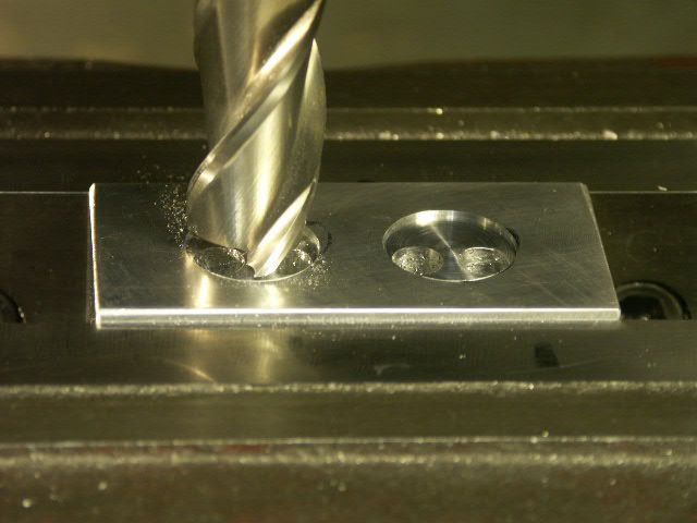
The bore diameter is .755", so I had to enlarge it a tiny bit with a boring head.
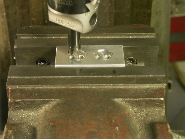
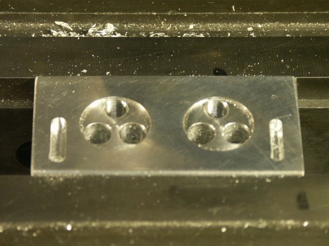
Next, drilling and tapping the spark plug holes. The distance from the cylinder head centerline to the spark plug center is a little ambiguous on the drawing due to the 80 degree angle of the spark plug and which surface it intersects, but I figured it wasn't too critical if it stayed within the combustion chamber.
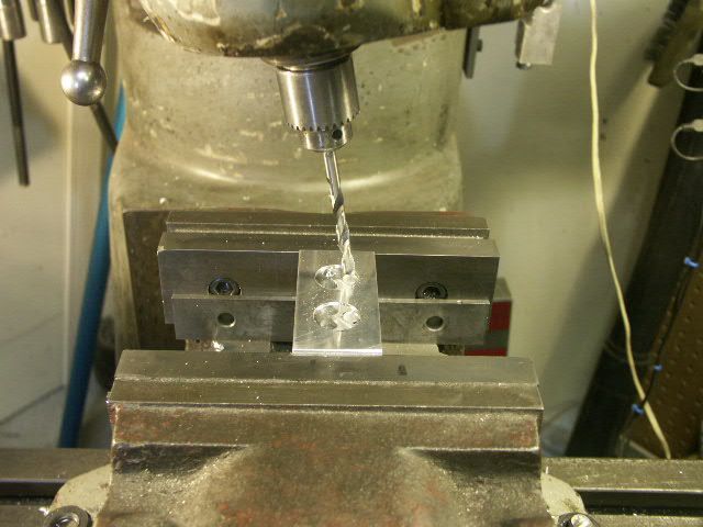
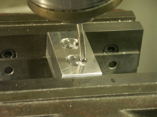
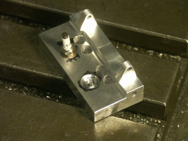
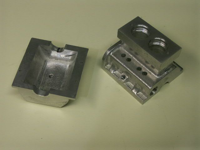
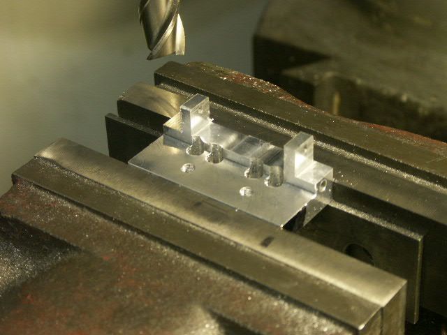
Then to flip the part over and carve out the camshaft support posts. The drawings SB-14 Rev 1 and SB-16 Rev 1 give contradictory dimensions for the width and location of these posts. Adding the .891" spacing from the far side and a width of .470" comes to 1.361", and not the 1.375" width of the cylinder head. This .014" difference is not too significant in itself, but it caused me some consternation since the drawings show the valve guide holes to be tangent to the face of this step. If that interpretation is true, the post width can't be more than .4275" due to the valve hole locations. I searched this site to see how others interpreted the drawings. I've posted below two photos by danthompson58 and Mosey show different approaches to this issue. Thanks, guys, for your help!

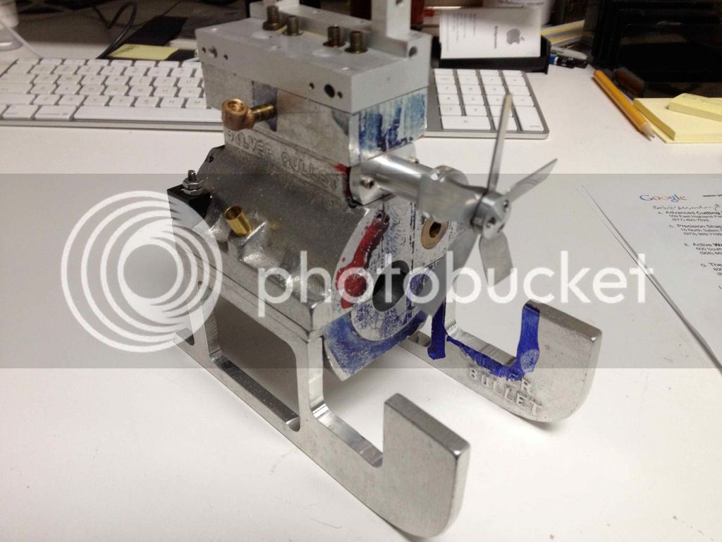
Cutting that step tangent to the valve guide holes comes pretty close to the cooling hole, and risks damage when one end of the hole is tapped and the other is plugged. Would not doing so interfere with the valve action? I chose to err on the side of not removing enough metal rather than removing too much. I can remove more later, if needed.
Bob

My kit didn't include the engine stands, but a friend made castings using the ones from his kit. Thanks, Birk!

I decided to start with the gears, since I had never made any before, after about 30 years in this hobby. A friend offered to let me borrow his brand new gear form milling cutters. What a treat! Thanks, Richard! But I was nervous every minute that they were in my possession so I got right to work on the 64 tooth gear.

I made enough for three gears, and then parted them off.


I then did the same with the 32 tooth gear. And returned the cutters ASAP.
It looked like the cylinder head was one of the more complex parts, so I started it next.
I squared up the block, and drilled the through holes for the coolant and cam shaft.

drilled and reamed the holes for the valve guides,

and milled the combustion chambers with a .750" end mill.

The bore diameter is .755", so I had to enlarge it a tiny bit with a boring head.

Next, drilling and tapping the spark plug holes. The distance from the cylinder head centerline to the spark plug center is a little ambiguous on the drawing due to the 80 degree angle of the spark plug and which surface it intersects, but I figured it wasn't too critical if it stayed within the combustion chamber.


Then to flip the part over and carve out the camshaft support posts. The drawings SB-14 Rev 1 and SB-16 Rev 1 give contradictory dimensions for the width and location of these posts. Adding the .891" spacing from the far side and a width of .470" comes to 1.361", and not the 1.375" width of the cylinder head. This .014" difference is not too significant in itself, but it caused me some consternation since the drawings show the valve guide holes to be tangent to the face of this step. If that interpretation is true, the post width can't be more than .4275" due to the valve hole locations. I searched this site to see how others interpreted the drawings. I've posted below two photos by danthompson58 and Mosey show different approaches to this issue. Thanks, guys, for your help!


Cutting that step tangent to the valve guide holes comes pretty close to the cooling hole, and risks damage when one end of the hole is tapped and the other is plugged. Would not doing so interfere with the valve action? I chose to err on the side of not removing enough metal rather than removing too much. I can remove more later, if needed.

Bob


