Sideshaft i.c. Horizontal engine

Home Model Engine Machinist Forum

Help Support Home Model Engine Machinist Forum:

This site may earn a commission from merchant affiliate links, including eBay, Amazon, and others.
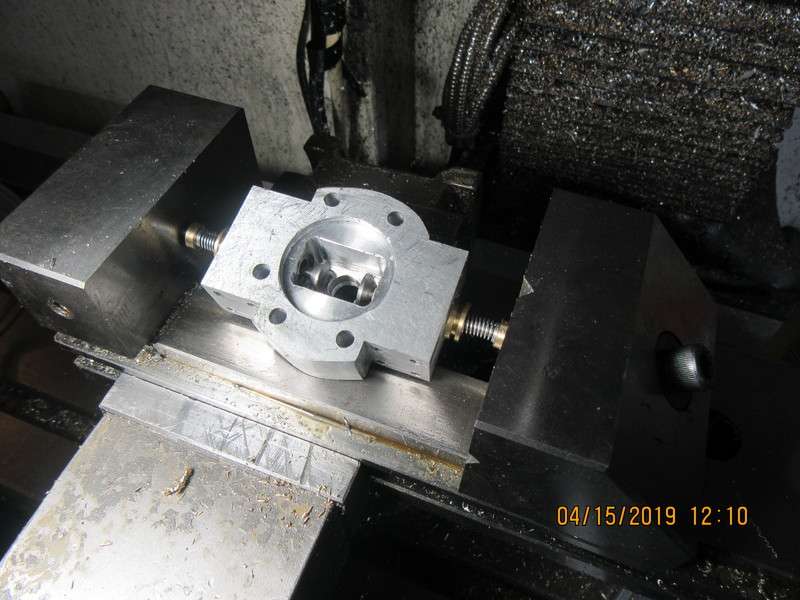
I had a very exhausting morning.--Oh, that's a horrible pun--I made the exhaust pipe and flange this morning. I should be making valves, but I need a break from machining things. The temperature outside is almost 60 degrees F and the glacier in my front yard is almost gone. I think I deserve a coffee from Tim Hortons, maybe even risk a big sugary donut. If I still had my hot-rod this would be the day for its first spring ride. Maybe a good dose of sugar and a drive around town will restore my creativity and I'll do the valves later today. ---Brian
lbgW4o.jpg
 
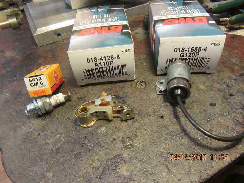
Went to Timmys, had a big coffee and an apple fritter, then went down to Partsource and bought a sparkplug, points, and a condenser. I use the same units on all of my engine. Cost is +/- $28 Canadian. Went to Kawartha Dairy and bought a small bag of curd to munch on.---Everything I like is either illegal, immoral, or fattening!!!
LwHhIf.jpg
 
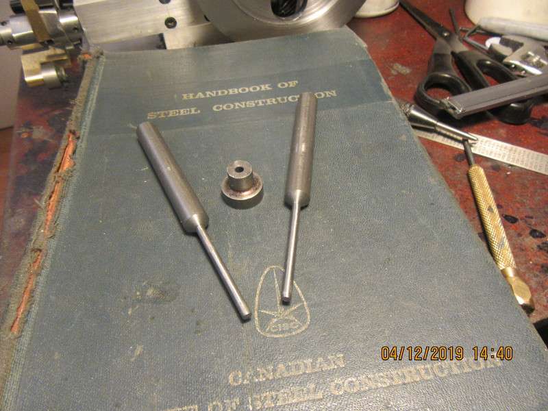
This afternoon I whittled out two valves. I keep my exhaust and intake valves the same size and length. I use plain cold rolled steel to make them from. They have not been trimmed to "finished length" yet. One interesting thing in this picture is the small piece of material setting between the valves. It is a scrap piece of cold rolled steel with a 0.125" hole reamed thru it. When I machine my valves, I leave them about .002" oversize. I work that last .002" down with a strip of aluminum oxide paper. I have learned from past experience not to trust my micrometer for the final diameter of the valve stems. Instead, I try and fit that piece with the hole reamed in it as a fitting guide. When the valve stems are reduced to the point where that piece will slide all the way up the valve stems, I know they are finished and will fit well into the reamed 0.125" holes in the valve cages.
7gGF6F.jpg
 
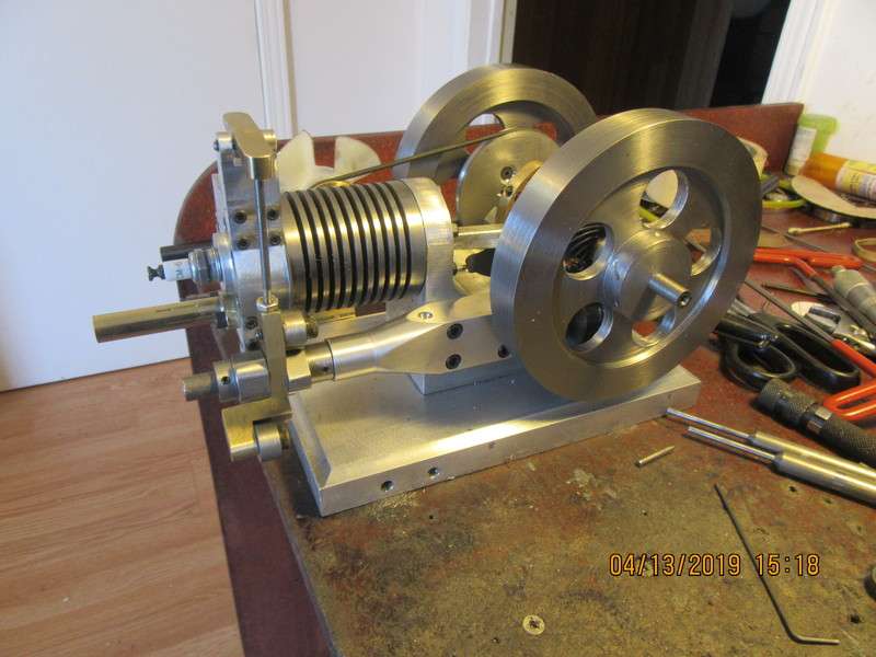
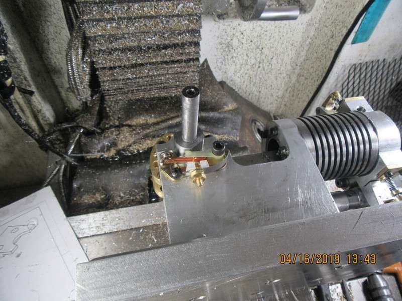
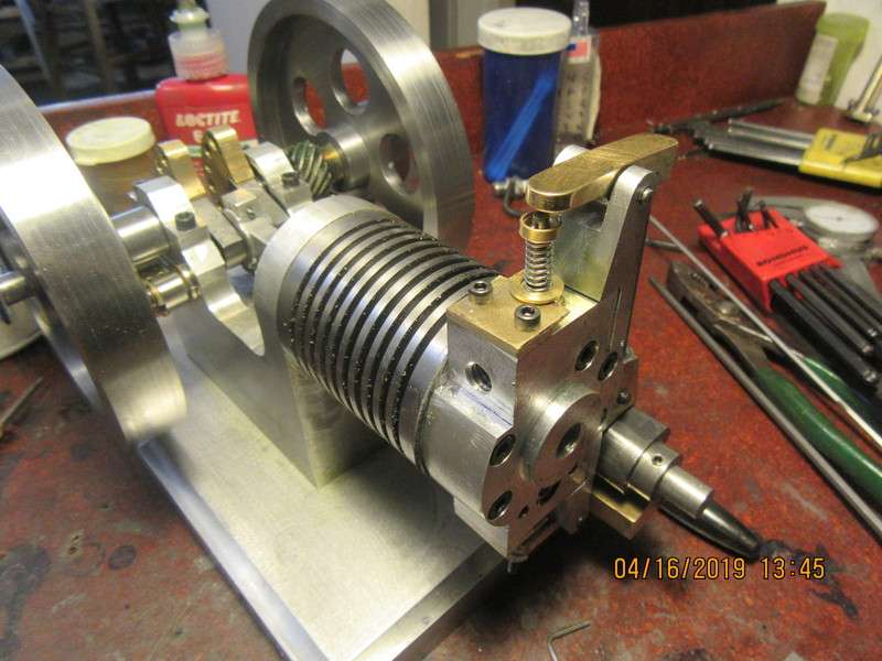
Nothing spectacular going on today. I did make up proper pivot pins for both rocker arms, and a small retainer bushing on the back sided of the fan shaft (which doesn't show up in this picture anyways.) One thing that I did do, and that I like very much--I took off the rectangular sideshaft bracket, mounted it in the four jaw chuck, and turned a round boss and a taper on the end of it. This was a purely cosmetic thing, but it really adds to the overall look of the engine, I think.
Tw0LDy.jpg
 
Thanks CFL Bob.--It's only a small "beauty touch" but things like that can make a big difference in the appearance of a rather plain looking engine.---Brian
 
Its been a horrible cold, wet, nasty day today, with light traces of snow and lots of rain. I had an inventor come this morning to discuss a new project he has in mind, and after he left I turned two valve cages and two valve spring retainers. I dug around in my box of assorted springs and found two springs the right diameter, but I'm not sure at this point if they are strong enough. Tomorrow I will use my George Britnel valve seat cutting tool to cut the seats into the cages, cross drill the end of the valves for a retainer pin, lap the valves into their respective seats, and maybe press the assembled valves and cages into the cylinder head.
fHgQBv.jpg
 
Yes, there is an oilite bronze bushing at each end of the aluminum part which has been tapered. a squirt of oil once in a while, applied thru that hole keeps things well lubricated.
 
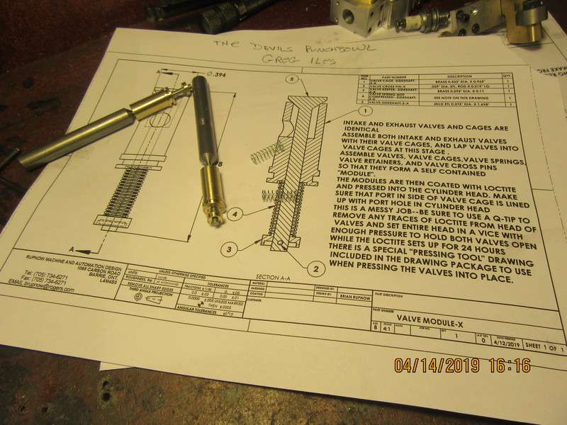
The valve modules have been completely finished. All appropriate holes have been added and the valves have been shortened to finished length and lapped into the seats before the modules are pressed into place. The valve cages were coated on the outside diameter with #638 Loctite before being pressed. The valves shouldn't have to be lapped any more, but if they need to be I can remove the spring and retainer and attach one of my finger chucks to the valve stem to spin it for a re-lap. The cylinder head is currently in a vice, which is closed enough to raise the valve faces up of the seats. That is "just in case" I may have got some Loctite on the valve faces. I don't want to Loctite the valve faces to the seats.
CFXr4I.jpg
 
Very nice. I have been following since the beginning.
I am getting ready to move to a new home and larger shop, but will have to store my tools for several months while the house is being finished. I have never gone that long without my lathe and workshop tools.
Starting to feel withdrawals already. I will have to just enjoy the everyone's work vicariously for awhile.
Mike
 
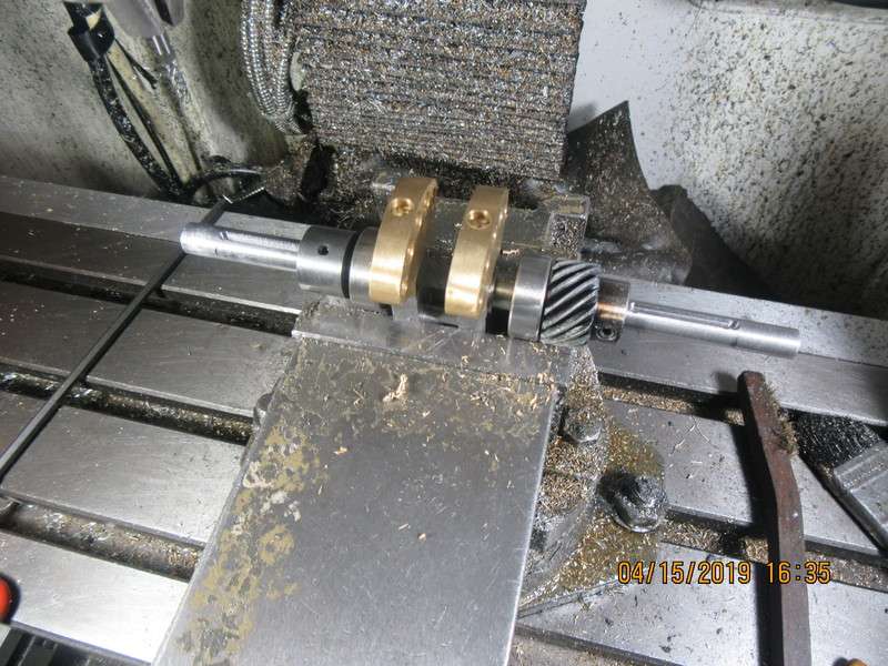
I knew that sooner or later I was going to have to cut keyways in this crankshaft, and today was the day. These keyways are just a little bit different, because they don't run out to the end of a shaft. I thought that they were called "pocket" keyways, but they are actually called "feather" keyways. I had to go across town and buy a couple of new 3/32" endmills because the one I had was broken. Not being able to find any pertinent information other than the correct name, I made it up as I went along. I ran the mill at 1150 rpm, poised the endmill over what would be the extreme end of the keyway, then very cautiously plunged to full depth--which in my case was about 0.053". This went well, so after plunging a total of four places I increased the depth from "0" to 0.053" in .005" increments and moved the table in x axis very slowly and cautiously from one end of the keyway to the other, with lots of squirt on cutting oil. All went well, I didn't break the endmill, and I have my keyways finished. I am still waiting for my broach to arrive so I can cut the keyways in my flywheels.
Ox5UtL.jpg
 
My broach came in today, but there was a problem. The one I ordered was a plain HSS broach, for $75 Canadian. The one that came in today was the right size but was TIN coated and costs $135 Canadian. Tomorrow will be negotiation time. I am not going to pay $135 but I don't want to wait for another two weeks to get an uncoated broach in. Apparently they come from some place in Virginia.
 
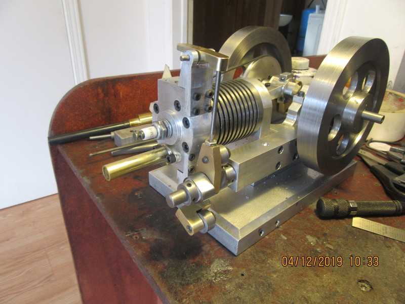
The engine is very close to being finished. This morning I am "running it in" with power provided by an old 1/2 hp. electric motor. Running an engine in is not intended to take out any major binding in an engine. That is something that has to be addressed with more machining on something. This type of run in is to address all the minor binding points.--Con-rod big end to crank journal, sideshaft to bushings, wrist pin to piston, and any "stickiness" in the valve train.
 
And now I'm snookered!! The wrong broach has been returned and I have to wait a week for the correct one to be shipped up to me. My intent was to make the first trials of this engine using a Traxxas Pro 15 carburetor, but my local hobby shop has stopped handling them and they can't even special order one for me. I do have a piece of the broken 3/32" broach here and I may try to use it with shims. Depending on how the coming week turns out, I may make another carburetor while I wait for the correct broach to arrive.
 
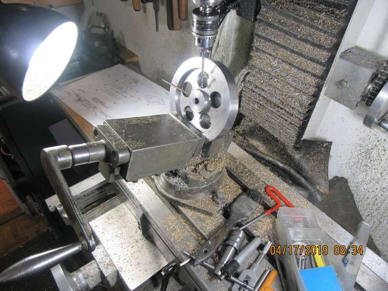
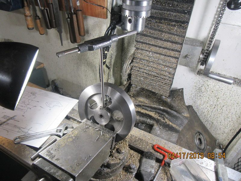
In order to have something to do, I went ahead and drilled and tapped the flywheel hubs for set screws. One set screw goes directly over the key and the other is 90 degrees offset. This is where my old "Tilt-a-whirl" vice really shines. Due to the fact that the hubs very seldom stick out past the width of the flywheels, these set screw holes must be drilled at an angle. I have a digital protractor which I use to set the vice to whatever angle of tilt I want and then drill the set screw holes. It helps a great deal if you have an extra long centering drill and an extra long tap.
aWh05U.jpg

kyllJh.jpg
 

Latest posts

Back
Top