Rupnow i.c. Engine with governor

Home Model Engine Machinist Forum

Help Support Home Model Engine Machinist Forum:

This site may earn a commission from merchant affiliate links, including eBay, Amazon, and others.
Yet PCD or pitch circle equals Number of teeth divided by DP 24/24 = 1

there is more then one type of pitch

then there is the real pitch

Pitch nomenclature[edit]

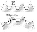
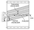
Pitch is the distance between a point on one tooth and the corresponding point on an adjacent tooth.[5] It is a dimension measured along a line or curve in the transverse, normal, or axial directions. The use of the single word pitch without qualification may be ambiguous, and for this reason it is preferable to use specific designations such as transverse circular pitch, normal base pitch, axial pitch.


  • Pitch


  • Tooth pitch


  • Base pitch relationships


  • Principal pitches


Circular pitch, p Arc distance along a specified pitch circle or pitch line between corresponding profiles of adjacent teeth.Transverse circular pitch, pt Circular pitch in the transverse plane.Normal circular pitch, pn, pe Circular pitch in the normal plane, and also the length of the arc along the normal pitch helix between helical teeth or threads.Axial pitch, px Linear pitch in an axial plane and in a pitch surface. In helical gears and worms, axial pitch has the same value at all diameters. In gearing of other types, axial pitch may be confined to the pitch surface and may be a circular measurement. The term axial pitch is preferred to the term linear pitch. The axial pitch of a helical worm and the circular pitch of its worm gear are the same.Normal base pitch, pN, pbn An involute helical gear is the base pitch in the normal plane. It is the normal distance between parallel helical involute surfaces on the plane of action in the normal plane, or is the length of arc on the normal base helix. It is a constant distance in any helical involute gear.Transverse base pitch, pb, pbt In an involute gear, the pitch on the base circle or along the line of action. Corresponding sides of involute gear teeth are parallel curves, and the base pitch is the constant and fundamental distance between them along a common normal in a transverse plane.Diametral pitch (transverse), Pd Ratio of the number of teeth to the standard pitch diameter in inches.
1a203fe304ff0e15ac8002250394c0a3.png
Normal diametral pitch, Pnd Value of diametral pitch in a normal plane of a helical gear or worm.
ace420b08910a7d0f929ba7e1ed3a084.png
Angular pitch, θN, τ Angle subtended by the circular pitch, usually expressed in radians.
d0591912146aa457b33bffd2bac9e80d.png
degrees or
809b70e6bcd8f70971948d2660ce5d58.png
radiansBacklash[edit]

Main article: Backlash (engineering)

pitch.jpg
 
Yes most suppliers catalogues would list the Pitch dia its the standard way to describe gears Tooth number-size either DP or MOD - PCD. and common sence would tell you its not the pitch between two teeth.

J
 
Thank you so much again Brian for sharing your talents and offering these drawings. Greatly appreciated!!!!
 
Yes most suppliers catalogues would list the Pitch dia its the standard way to describe gears Tooth number-size either DP or MOD - PCD. and common sence would tell you its not the pitch between two teeth.

J


I know this but "common sense" also tells you not to assume something
that your not sure of. and because I'm putting one together I wanted to be certain. That's why the question was for Brian and NO ONE ELSE
 
Luc--Please don't start a row. Jason is only trying to be helpful. Sometimes things get a fit "fuzzed" in translation. Gknipp---Hope you join us all and build one.---Brian
 
Luc--Please don't start a row. Jason is only trying to be helpful. Sometimes things get a fit "fuzzed" in translation. Gknipp---Hope you join us all and build one.---Brian

It's not my goal Brian, but being told "common sense" does not belong
in an answer. Next time I'll PM you instead

cheers
 
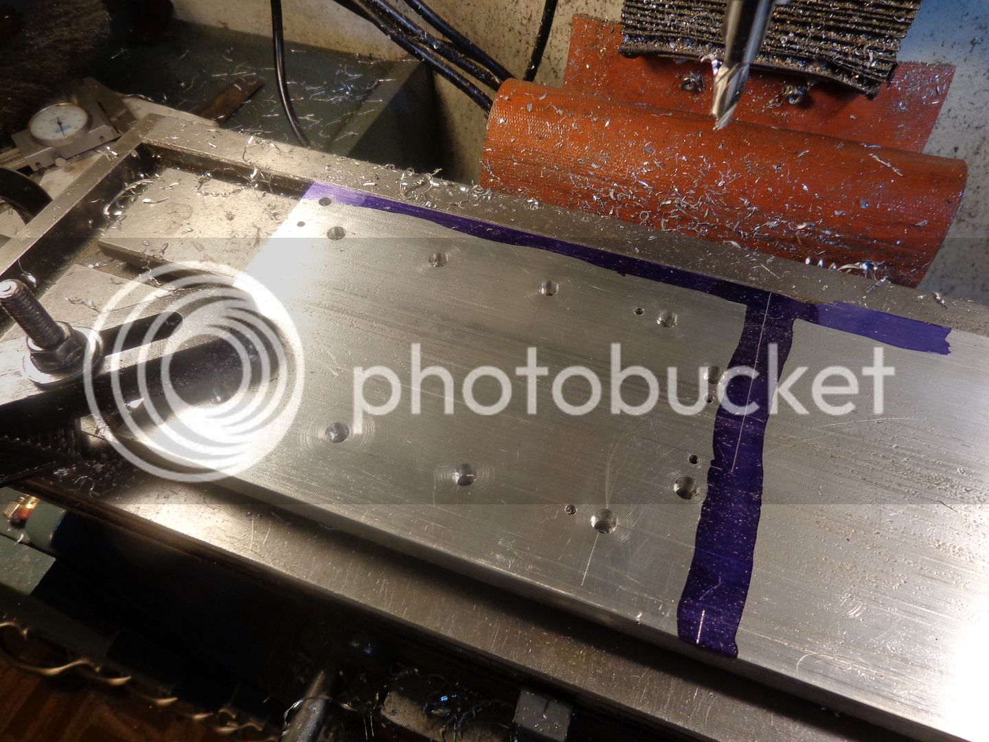
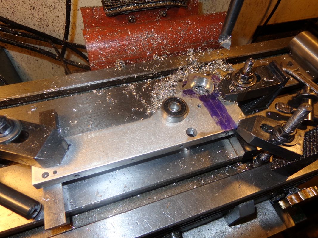
Here we have 99% of a base. I am drilling the 1/8" dowel holes in this plate but leaving them .031 undersized. (There is one I couldn't get to because a toe clamp is in the way) . I will assemble the base and sideplates and get everything "squared up" and the bolts tightened, then use these as guide holes to drill thru into the sideplates, then ream them and add 1/8" dowels. I got this far into the build and realized that I didn't have a counterbore tool for a #8 shcs., but a 9/32" end mill is just the right size, so I used it to counterbore the 10 holes. The only missing hole (other than the one where the toe clamp is) is the threaded hole for the governor spring adjuster post. I have decided to drill it after everything is assembled.
 
We have a base!!! After I got all the holes finished, I took it off the mill and turned it over, and what did I see?? A great big nasty scratch right down the middle of the part, about .015" deep. I didn't do it. It was there when I bought the aluminum--I just didn't notice it. Not wanting to do any more machining on the face of the part, I dug out my seldom used belt sander and bullied the scratch into submission. Then a bit of time with my jitterbug sander, and the scratch is gone. While I was down at the metal supplier this morning, I held my breath and asked "How much?" for 8 1/2" of 4" x 3/4" brass.---Flywheels ya know. The counterman looked it up in the big book and said---(Gasp)---$55!!! . I don't know if the Rupnow fortune could take a hit like that or not.---But Damn, polished brass flywheels and flyballs would sure set it off nice!!!.
 
I held my breath and asked "How much?" for 8 1/2" of 4" x 3/4" brass.---Flywheels ya know. The counterman looked it up in the big book and said---(Gasp)---$55!!! . I don't know if the Rupnow fortune could take a hit like that or not.---But Damn, polished brass flywheels and flyballs would sure set it off nice!!!.
http://s307.photobucket.com/user/Br...BUM1/ALBUM THREE/BASE003_zpse0906a8a.jpg.html

Hey Brian
arelation of mine have a huge steel fabricator company he probably buys 2 to 3 million a year of stuff, I'll ask him to get me a quote
what if we get 4.250 shaft 2inch long :confused: it but cut on the metal saw after
 
Luc--There is one problem with making flywheels from round stock. I find that to make a flywheel 1" wide, I have to buy a piece of material 2" long so I have something to hold onto in my chuck. I asked about the bar today, will probably ask about the price of round stock on Monday. I haven't got real serious about the flywheels yet, as I have a lot of work to do before I'm ready to make them.
 
G'day Brian,
If you have limited round stock, how about you hold one side then face one side and drill the centre.
Then turn it around and bolt it to a mandrel that ten allows you to machine the OD .
Then if you want hold it back in the jaws, face to width and any recess or boss required and bore to size.
Just an idea ?

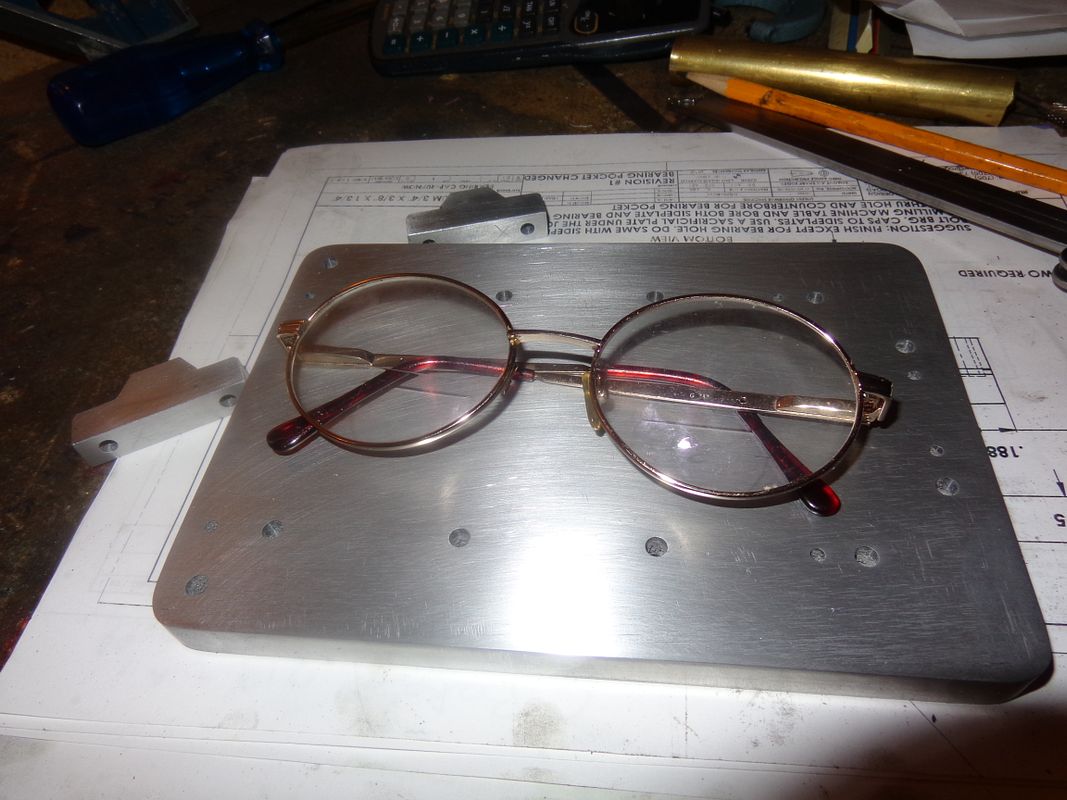
Also I am just having a bit of fun and I hope you don't mind the picture.
Cheers.

01.jpg
 
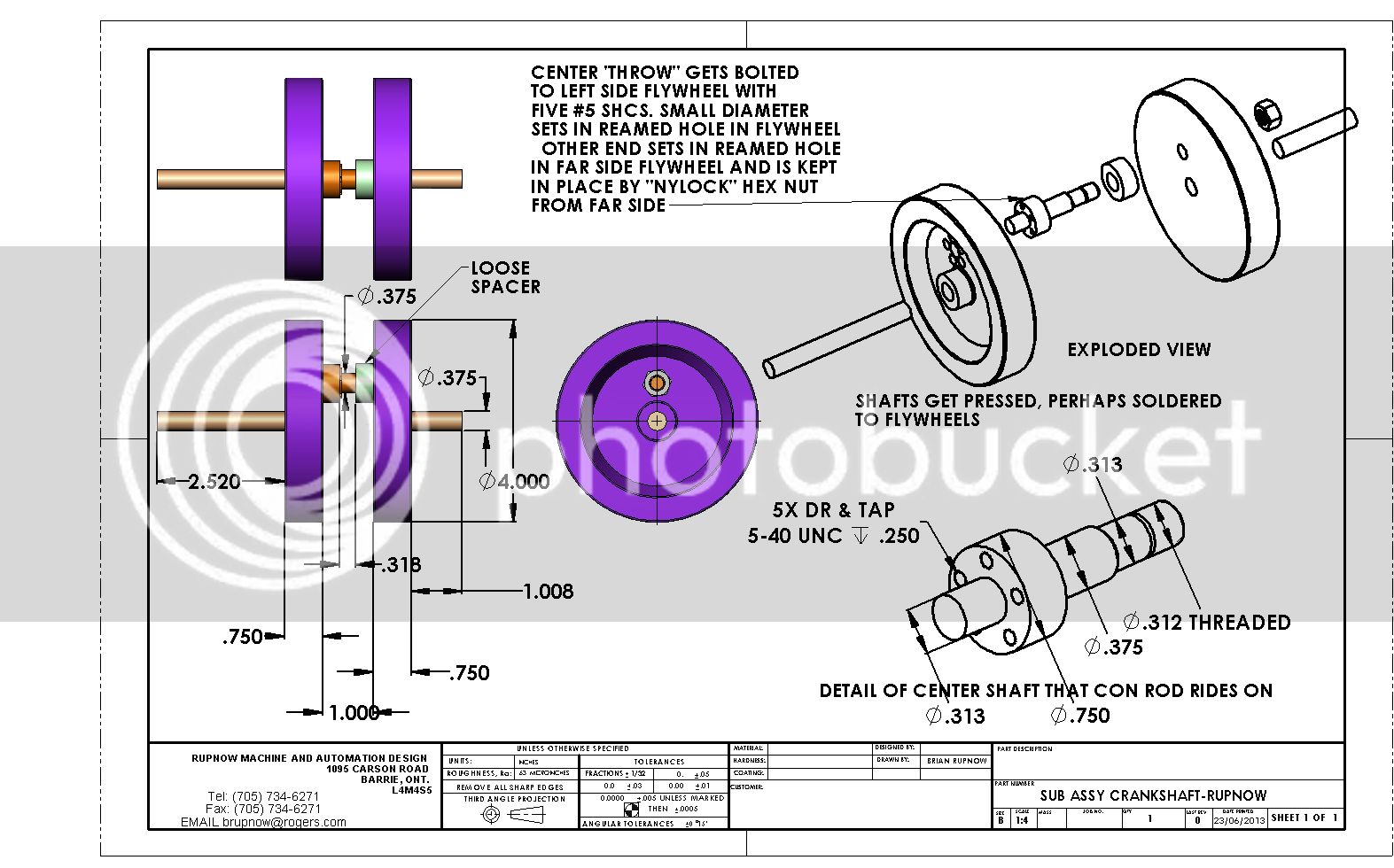
Thanks Sasquatch. While I'm waiting for some layout dye to dry, I thought I would modify the crankshaft slightly and put up a new drawing to show what I intend to do. This method of building the crankshaft lets me run a ball bearing on the big end of the con rod. I haven't built a crank like this before, but I understand the overall design is quite commonly used in some motorcycles and snowmobiles.
 
Last edited:
The trick to this type of crankshaft is to get everything aligned just right with no runout or wobble.
 
Nice engine design, Brian. I will add it to my list of engines to build someday! Sorry you had to cut your trip south short. I am good friends with aonemarine and I would have liked to meet you. I enjoy your engine designs and postings. Thanks for your contributions.
cheepo45
 
Today I built the two sideplates, tapped all of the holes, and got one sideplate bored, but my old butt is dragging and I think I will leave the other side to be bored tomorrow. If anyone wants to know WHY that 3/16" reamed hole looks so damn big----Its because it IS. I misread the drawing and drilled it 3/16" up from the bottom of the plate instead of the 5/16" the drawing calls for. I caught it before I had torn the set-up down (I was drilling both plates together) so went back and put in a 3/8" hole in the correct place. I will make a brass bushing to go in there and people will think it was supposed to be like that!!!
 

Latest posts

Back
Top