QCTP again

Home Model Engine Machinist Forum

Help Support Home Model Engine Machinist Forum:

This site may earn a commission from merchant affiliate links, including eBay, Amazon, and others.

JimM

Well-Known Member
Joined
Jan 6, 2009
Messages
170
Reaction score
0
Hi all

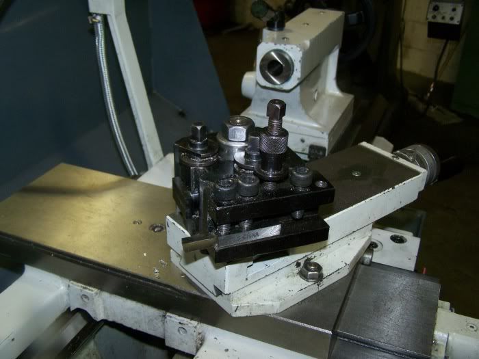
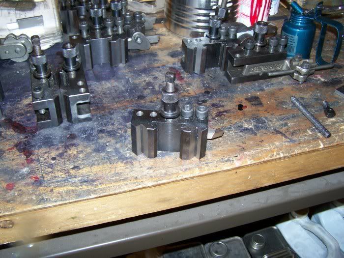
I'm currently using an 'economy' QCTP like the second one down on this page

http://www.chronos.ltd.uk/acatalog/Chronos_Catalogue_Quick_Change_Toolposts_69.html


Although it does work it's not the best bit of kit on the market - I particularly have problems when parting off, the whole toolholder can move ! As I need some more toolholders I'm thinking I may be better off starting over again and getting something a bit more upmarket.

As I'm in the UK and working on a hobbyist budget the choices are fairly limited but thinking the piston type tool post at the bottom of the same page may be suitable. Does anyone have any experience of these particular models, I'm assuming it's a Chinese import but are they all the same ? Also am I likely to see a decent improvement over the current post or am I going to have to spend even more money :(

Many Thanks

Jim

 
I particularly have problems when parting off, the whole toolholder can move !

That is obviously a problem but what is moving and why. Is the main block able to move on the compound or is the tool holder moving on the block. Neither of these should move unless the whole assembly is flexing or is the lathe itself flexing?

As for the piston type Chinese QCTP, I used one on a 10" Southbend with good success but for the few dollar more, I prefer the wedge type. The piston type holds the tool holder by pushing it away from the block while the wedge type pulls it in.
 
I've been using the piston type for a couple of years on a Sieg lathe with no problems.

In fact it's proven to have been one of the lathes better points !

I'm in the midlands, Nott's/Derby's Jnc 26/27 M1 if you want to looksee.

I can't comment on your type of post but are you sure it's the post that is the problem?
 
What type/size lathe are we talking about? The Seig lathes have notoriously limp compounds and benefit immensely from having them replaced with a solid metal post. Mine had so much flex that it was impossible to use a parting tool. Now it is solid as a rock.
 
I'm using an Atlas 10F lathe, similar looking to the Myford ML7

I'll have to have a better look at the current toolpost to determine why things are moving when parting.

Cheers

Jim
 
websterz said:
What type/size lathe are we talking about? The Seig lathes have notoriously limp compounds and benefit immensely from having them replaced with a solid metal post. Mine had so much flex that it was impossible to use a parting tool. Now it is solid as a rock.


websterz, Can you show a pic? I have 7 x 12 and the compound moves quite a bit. Its scary sometimes,, aahh well, always! :big: :big:

Ron
 
JimM said:

I think the one labeled MX90 is the ones on the 8 lathes at school. They don't use any
dovetails but a pair of 90 deg. Vs and are really sturdy If I was going to tool up a lathe
That is what I'd use. I've been using the ones at school for 6 or 7 years and haven't
found any thing I'd do different. I haven't tried to make any holders but should be
able to with a mill and a tilt table to do the Vs with a standard milling cutter, ie.
no "dovetail cutters". :) There is a T cut but that should be a lot more forgiving
than the sharp "point" on the dovetail. The elevation adjust is very good also.
I may have a few pix if I can find them .
...lew...
Oct312008006.jpg


Oct312008007.jpg
 
ozzie46 said:
websterz, Can you show a pic? I have 7 x 12 and the compound moves quite a bit. Its scary sometimes,, aahh well, always! :big: :big:

Ron

screws.jpg


In this pic you can see the plinth mounted on top of the lathe cross-slide. It is actually a 2 piece, aluminum on top steel on bottom. I didn't have a tall enough piece of steel at the time. 8) On top of the plinth you can just see the base of my toolpost. Making the plinth is simple, just mill a block of material to the right height, drill 2 thru-holes and a central locating hole that match the disc that formerly held the compound, and then cut a shallow spotface, .050" is deep enough. The spotface ensures good clearance and contact with the top of the cross-slide. I drilled and tapped 2 stud holes in mine, one in the middle and a second off center, between the mounting holes. That way I have additional reach built in. If I need to turn something bigger on the lathe I can mount the toolpost in the back hole, giving me about 3/4" extra reach. Hope this helps.


Thanks web, I remember seeing that earlier, but I some times get tunnel vision. I was more interested in your saddle lock setup when I first saw it.

Ron
 
ozzie46 said:
Thanks web, I remember seeing that earlier, but I some times get tunnel vision. I was more interested in your saddle lock setup when I first saw it.

Ron

I have a bunch of pics to take out in the shop today, I will get you some good detailed pics of the plinth on and off the machine.

Todd
 
As promised, here are the pics:

top.jpg


The four capscrews hold the aluminum top onto the steel bottom of the plinth. I didn't have a big enough piece of steel. ::) The green stuff is air filter material, just keeps the chips out of the mounting holes. You can see the second stud hole and how much extra reach I can get by moving the post back when I need to.

underside.jpg


Here you can see how the plinth attaches to the mounting disc.

post.jpg


The post is stainless steel, 1" in diameter.

boring.jpg

turning.jpg


A couple of tools mounted up and ready to use. The holders are made from 7075 T6 aluminum.

And here is a video showing my rear mounted parting tool in action:

http://s797.photobucket.com/albums/yy258/websterzdesign/?action=view&current=rear_toolpost_xvid.flv


Thanks web, Looks like I have yet another project. :big: :big: :big:

Ron
 
Thanks for the vid.
I always like vids that include the handwork. Very helpful to the inexperienced (me).
 

Latest posts

Back
Top