- Joined
- Dec 2, 2008
- Messages
- 971
- Reaction score
- 9
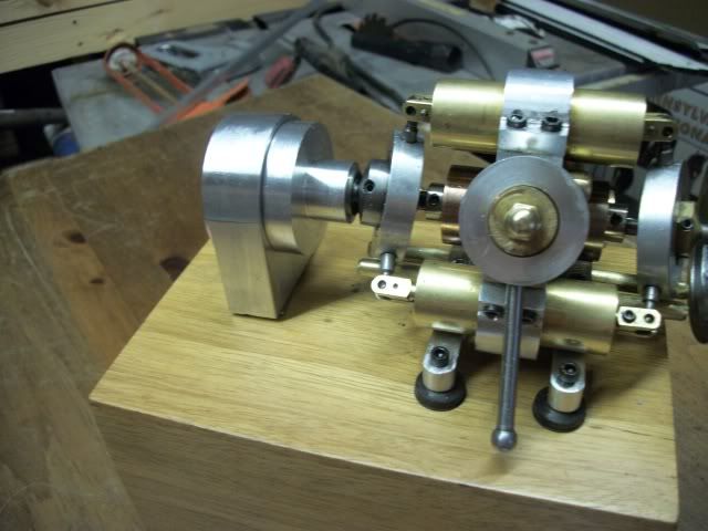
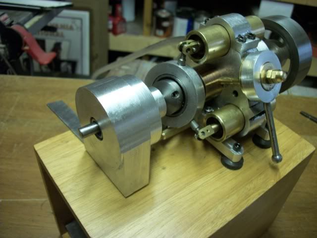
Today I assembled a planetary gear box salvaged from a discarded portable drill. I didn't get any pictures of the process because there was no real plan, and lots of frustration and grief. I was only interested in the gears so the chuck and motor were just sawed off. The gearing in the drill used a double reduction to get the torque needed for a 3/8 drill from a high speed, low torque universal motor. The total reduction was about 25:1. The engine that I am going to use this with seems to get its maximum power output at around 600 rpm so I decided to use only one planetary gear set with a reduction of 5.25:1 so I should get an output shaft speed of around 150 rpm at full load.
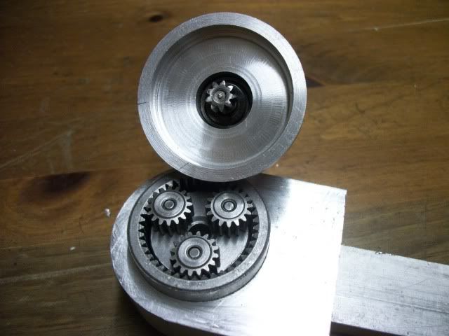
I don't have any plans for a high load application yet but the challenge was fun. I'm not going to post any plans or dimensions because I doubt that all drills use the same gear specs. The project is really simple. Find some way to hold the internal ring gear. Find some way to support the input and output shafts and keep everything in line. To hold the ring gear (1.489" OD) I used an boring head in the mill to bore a close fitting blind hole in a block of aluminum. The ID of the ring gear at the tooth tip measured just a hair over 1.125" which was a real break because I have a supply of ball bearings with that dimension on the OD and a .500" bore. With the ring gear pressed into the bored cavity, the bearing is a tight fit in the gear and a little Locktite will keep it in place.
The planetary gear carrier shaft was less than .500" diameter but to close to make a bushing so I had to reduce it to .375" and the make a bushing with a shoulder to locate the carrier plate clear of the bearing face. The sun gear pinion had been mounted on the end of the motor armature but I was able to free it with some heat and persuasion and then turn a matching shoulder on a .250" steel shaft for the input. I had a pair of bearings with .250" bore and .750" OD so I turned a chunk of aluminum with a .750" bore to a 1" depth to hold the two bearings separated by a spacer. This piece was also bored out on one face to about 1.5" diameter to fit over the ring gear that protrudes about .250" from the base housing. A collar locates the shaft against the outer bearing and that is all there is to it. Some cosmetic work on the lathe and mill and the results are shown below.


I don't have screws long enough to clamp the two housing together so tomorrow will be a trip to town for some fasteners.
I believe that I read somewhere that small generators need to be spun up to get good output so with a 5.25:1 increase I should be able to turn up about 30,000 rpm. I have a scrap laser printer that should yield some motors that might work as a generator.
More to come.
Jerry
I don't have any plans for a high load application yet but the challenge was fun. I'm not going to post any plans or dimensions because I doubt that all drills use the same gear specs. The project is really simple. Find some way to hold the internal ring gear. Find some way to support the input and output shafts and keep everything in line. To hold the ring gear (1.489" OD) I used an boring head in the mill to bore a close fitting blind hole in a block of aluminum. The ID of the ring gear at the tooth tip measured just a hair over 1.125" which was a real break because I have a supply of ball bearings with that dimension on the OD and a .500" bore. With the ring gear pressed into the bored cavity, the bearing is a tight fit in the gear and a little Locktite will keep it in place.
The planetary gear carrier shaft was less than .500" diameter but to close to make a bushing so I had to reduce it to .375" and the make a bushing with a shoulder to locate the carrier plate clear of the bearing face. The sun gear pinion had been mounted on the end of the motor armature but I was able to free it with some heat and persuasion and then turn a matching shoulder on a .250" steel shaft for the input. I had a pair of bearings with .250" bore and .750" OD so I turned a chunk of aluminum with a .750" bore to a 1" depth to hold the two bearings separated by a spacer. This piece was also bored out on one face to about 1.5" diameter to fit over the ring gear that protrudes about .250" from the base housing. A collar locates the shaft against the outer bearing and that is all there is to it. Some cosmetic work on the lathe and mill and the results are shown below.


I don't have screws long enough to clamp the two housing together so tomorrow will be a trip to town for some fasteners.
I believe that I read somewhere that small generators need to be spun up to get good output so with a 5.25:1 increase I should be able to turn up about 30,000 rpm. I have a scrap laser printer that should yield some motors that might work as a generator.
More to come.
Jerry


