OPV Engine

Home Model Engine Machinist Forum

Help Support Home Model Engine Machinist Forum:

This site may earn a commission from merchant affiliate links, including eBay, Amazon, and others.

b.lindsey

Project of the Month Winner!!!
Project of the Month Winner
Joined
Jan 3, 2008
Messages
2,085
Reaction score
17
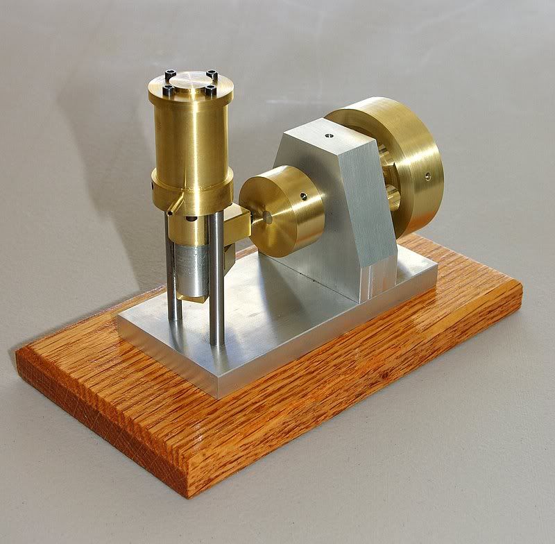
As requested here are a few pics of the Oscillating Piston Valve Engine as shown in the avitar. Its not really a build thread but maybe the pictures will suffice. Will be glad to answer any further questions as well.
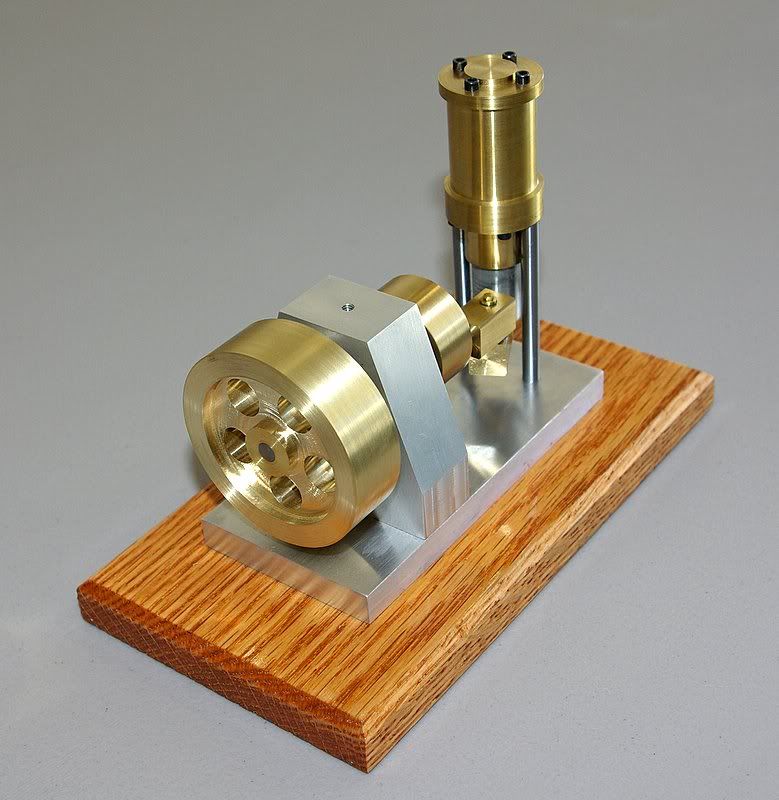
OPV1.jpg


OPV2-1.jpg


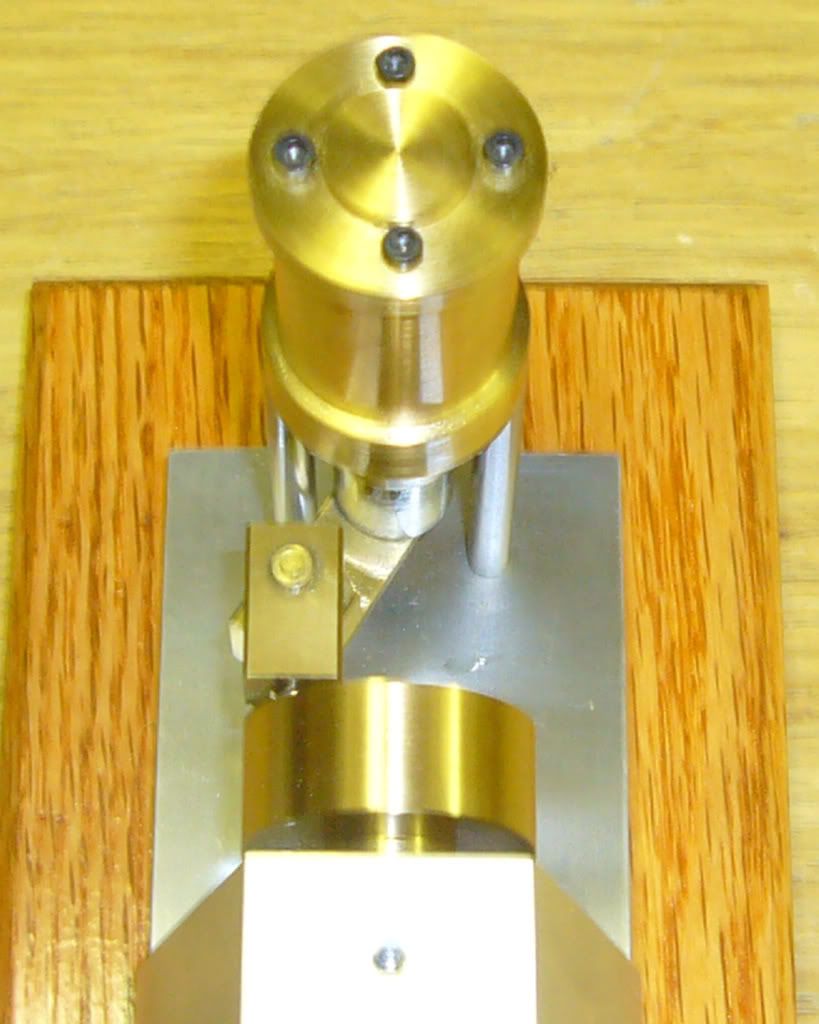
Here's a closer view of the piston/crankdisk linkage
OPV003.jpg


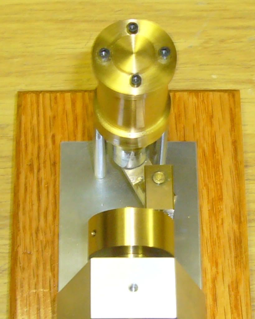
Two views from above showing the swing of the linkage as the crankdisk rotates.
OPV004.jpg


OPV005.jpg


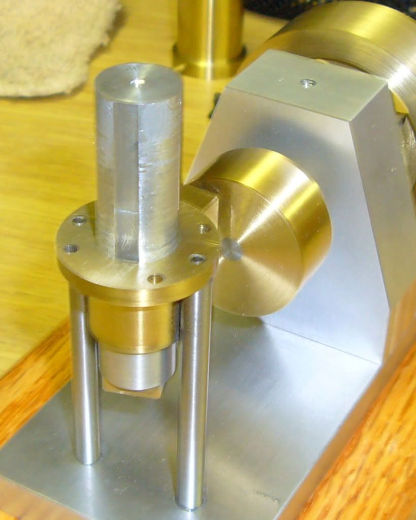
A view of the piston with the top of the cylinder removed showing the "flat" which acts as the valve mechanism as it rotates between the inlet and outlet ports.
OPV006.jpg


Finally a short video or it running with apologies for the website plug at the end (didn't have time to edit it out)


Hope this helps.

Regards,
Bill
 
Now that's interesting!

And a nice smooth runner as well.
 
Various versions of this engine were featured in "Model Engineer" some years ago.

Here's my take on it built to one of the plans from the magazine...

novalve.jpg


Since the engine is mechanically symmetric, it's possible to reverse it by simply interchanging the input and exhaust ports.

The motion of the linkage is mesmerizing and the engine is always an attention getter at shows.
 
It is an interesting though quite simple motion and easily reversed as Marv points out. If I had it to do over again or when I have the chance to make some modifications, I would probably use aluminum rather than brass for the two link parts. Being single acting, having to lift the additional weight on the upstroke tends to make it lope a little at slower speeds and I think aluminum links might help that. Otherwise it runs quite well and the loping seems to go away at higher rpm's.
 
Hey Bill,

Thanks for the pictures. That sure is a neat engine. Where did you get the plans for it?

Marv,

Do you happen to which issues have that engine in it?

Many thanks
Eric
 
Brass_Machine said:
Marv,

Do you happen to which issues have that engine in it?

It's called "Simon Junior" and the plans were in several issues starting in June, 1992. The author's name is Ted Pepper.
 
mklotz said:
It's called "Simon Junior" and the plans were in several issues starting in June, 1992. The author's name is Ted Pepper.

Thanks Marv!

I think it would make an interesting present for someone this Christmas.

Eric
 
Eric,
As I recall I saw a picture of the concept and went from there. Unfortunately I haven't seen the Model Engineer versions Marv referred to, so i wasn't sure about the linkage but knew what it had to do in theory. Just fiddled around in AutoCad a bit to make sure there wasn't any interference with the support pillars for the cylinder and went from there. I tried to keep the lines as simple as possible.

Bill
 
wlindiii said:
Eric,
As I recall I saw a picture of the concept and went from there. Unfortunately I haven't seen the Model Engineer versions Marv referred to, so i wasn't sure about the linkage but knew what it had to do in theory. Just fiddled around in AutoCad a bit to make sure there wasn't any interference with the support pillars for the cylinder and went from there. I tried to keep the lines as simple as possible.

Bill

Bill,

So you version is self designed? Do you mind sending me a copy of the plans? I won't be upset if you say no. I do understand these things.

Eric
 
I also think this is a very smart and intriguing engine. Could somebody explain the theory of it? I want to make something for my son for xmas but am bored of making the usual oscillating engines!

Nick
 
Nick,
There is a flat in the piston which rotates between the air inlet and exhaust outlet. The rotart motion of the crankdisk translates through the linkage so that the piston rotates (or oscillates) +/- 30 degrees so that the flat alternately lines up with the air inlet (forcing the piston down) or the exhaust outles (allowing the air to escape on the upstroke. Thats a simple explanation but hope it helps. I may can post a 3D wireframe that shows it better....I will try.

Bill
 
See if this helps. please note the ports are not shown on the drawing but you can see where they are from the pictures.

Bill

 
Thanks for that Bill, I understand how it works now, I just need to work out some dimensions and get things straight in my head!

Things like the length of the flat is critical ... is it right to think that the point where the flat stops, must be no higher than the top of the ports, even when the piston is at TDC ... otherwise it'd be trying to compress the air in the cylinder? Also, the width of the flat must be the same as the distance between the ports, to where the holes start. If it's narrower compression of the air will momentarily occur and if it's wider some air will momentarily leak straight back out of the exhuast, don't suppose these would actually stop it running though.

I was initially struggling to see why the piston was so long and the amount of cylinder above the ports but I think it's because the piston has to be long enough to still be above the top of the ports and cover them even at BDC?

This isn't as simple as it first looked!

Thanks again,

Nick
 
Bill,

Been thinking more about this, trying to come up with a simple design but got a quick question. Does the block that goes on to the crank pin slide back and forth on it?

Thanks,

Nick
 
Nick,
In this case you have to think both in the up and down directions between TDC and BDC but at the same time where the piston is in its rotation +/- 30 degrees as noted earlier. The flat does not actually bridge the distance between the input and exhaust ports but something less. In my case the piston is .500 in diameter and the flat is cut only .010 deep. Your assumption as to the length of the flat is pretty much correct but that is less critical then the .010 depth of the flat. I learned that through trial and error mostly. The piston is rather long but must run the length of the cylinder and enough to reach down to the lower link. Note that there is a flanged cylinder extension on the bottom even if the seam doesn't show in the pics. This is done to add additional support to the piston much like a crosshead. Otherwise at BDC there would be little contact between the cylinder and piston causing potential binding and/or wear.

As to your second point, the upper link has a 1/8" crankpin loctited into it. This pin is allowed to slide freely in its mating hole in the crankdisk. Again for support reasons, the crankdisk is thicker than you would otherwise expect.

Hope this helps.

Bill
 
Absolutely infuriating when pictures, etc, are scrubbed/deleted out of older threads, rendering them utterly useless for reference. Far too much of this kind nonsense on this, and other forums.

Frank
 
Generally, at least on this forum, it's the poster that removes or deletes the pics for one reason or other, rather than the forum admins. People either re-organise on their hosting site or purposely delete or modify their accounts so the images are removed from old posts.

It's annoying but realistically the original posters need to shoulder the blame.
 

Latest posts

Back
Top