Odd Camshaft design idea

Home Model Engine Machinist Forum

Help Support Home Model Engine Machinist Forum:

This site may earn a commission from merchant affiliate links, including eBay, Amazon, and others.

pyro4826

Member
Joined
Sep 12, 2013
Messages
7
Reaction score
2
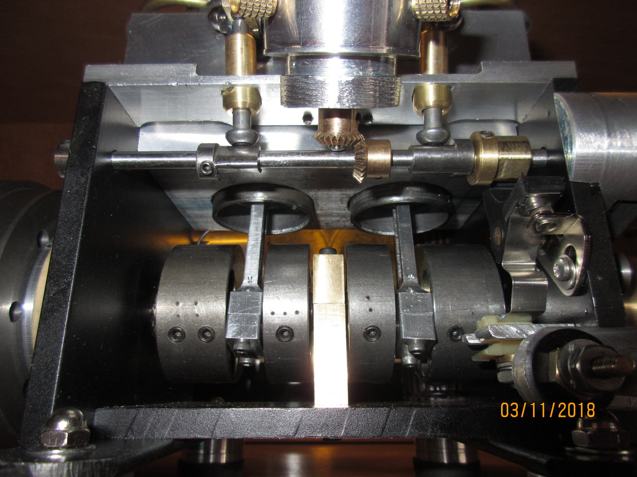
I've been working on coming up with a replacement head design for a scale Miata engine and am stuck on camshaft design. I am trying to replicate the Fiat/Abarth Triflux head. However I am struggling to come up with a camshaft that you can adjust timing on because there's no way to get it timed just perfectly without having to make a bunch of cams and swapping them out with different settings each. The triflux engine for those that don't know uses an intake and exhaust port on each side with 4 valves per cylinder.

What I was thinking was something like a main shaft with one set of lobes on it that has a rod running through it. When that rod is tightened it hold the other four lobes in place with friction. Timing would be a pain to set up but maybe with a set of holes in the free floating lobes that could aid in aligning the lobes when tightened up.

Any idea suggestions would be lovely. I know its a wild design idea.

--Will
 

Attachments

  • triflux engine.jpg
    triflux engine.jpg
    68 KB
Not sure if this helps but in the V8 you simply put the cam gear, Pulley in your case, on the cam shaft and set the cam timing, then snug up a single grub screw. It will dimple the shaft a bit but if you ever take it apart you can get it back together exactly the same as the grub will settle in the same dimple. If you are unhappy with the original spot just index the pulley a few teeth and make a new dimple. I have never had a problem with it and the V8's first run was 2011.
 
I understand what you are referring to, but what I guess I'm getting at is that I am not entirely sure if my cam timing is going to be correct and with the exhaust and intake lobes running on the same camshaft there isn't a way to adjust the timing without making a whole new camshaft. I'm used to a DOHC timing and haven't messed with timing of any SOHC and I guess this is in a way just an odd split SOHC setup. I don't trust that I have my lobe setup correct since it is a new learning area for me on designing a cam. It is loosely based on a Miata cam. STL file is what I have come up with if anyone wants to look at it.
 

Attachments

  • miata camshaft v5.stl
    128 KB
If you know what the lift, duration, and lobe separation of the cam you want to copy I have a method of making sure all the lobes are orientated correctly on the shaft. You can also have a radius on the flank (area where lift is happening) instead of the flat flank you have drawn. It involves making a fixture and then cutting the shaft on the lathe. When I did my V8 cam it took about 5 hours manually.
DSCN1853s.JPG
 

Attachments

  • Offset turning the camshaft.pdf
    736.9 KB
It would be nice to have some help making that since its new to me a bit. I do not have a cam that I am trying to copy exactly, I'm just referencing the miata cam for the general shape. I feel like the duration and lift should be the same since all the other dimensions are the same such as stroke and bore.

--Will
 
What I was thinking was something like a main shaft with one set of lobes on it that has a rod running through it.
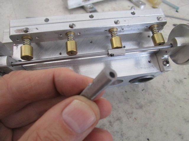
That works for me well. I make the cams lobes as a separate unit from the shaft for my engines. Then you can position the lobes over the valve or under the lifter to any timing spec you need and can vary cam timing at will to see how the engine responds.
 
Do you run a thick tube to space the lobes or just a thin tube to space and hold them?
 
No tube. I use a 3/16 in. or 1/8 in. dia. CR shaft. The lobes start out upon either 5/16 in. or 3/8 in dia. CR stock. Locked to the shaft with #4 or #6 set screws.

Q1EDt23.jpg

Wny3S18.jpg
 
Last edited:
No tube. I use a 3/16 in. or 1/8 in. dia. CR shaft. The lobes start out upon either 5/16 in. or 3/8 in dia. CR stock. Locked to the shaft with #4 or #6 set screws.

Q1EDt23.jpg
Ahhhhh I see! very clever and simple.
 
Just wondering...........
Would it be possible to make cams using a filing rest on a lathe and a vertical slide? Indexing would have to be done obviously.
Jack
 
Sure. Old time machinists were taught to file a perfect cube as part of their apprenticeship, or so I've heard. I have no doubt one of those old-timers with a file could make cams at least as good if not better than I can with all of my tools. They might even be faster than me, at least for one or two cams, due to the setup times. Meanwhile, I have to use the tools to make up for what I lack in experience and hand skills.
 
Sure. Old time machinists were taught to file a perfect cube as part of their apprenticeship, or so I've heard. I have no doubt one of those old-timers with a file could make cams at least as good if not better than I can with all of my tools. They might even be faster than me, at least for one or two cams, due to the setup times. Meanwhile, I have to use the tools to make up for what I lack in experience and hand skills.
 
I served my apprentiship with CAV in Rochester UK, for those who dont know they were a major auto parts manufacturer later Lucas Ind now who knows. our first filing job was a 1" cube that was produced just using a file and square it had to be square in all planes and accurate to .005" only using calipers and a slip for setting, the instructor used a Mic to mark it, this tought you to feel the measuring, when it passed, holes were drilled like a dice marked out with a rule and scriber, they had to be size to depth and positionally accurate, I cant remember the tolerance. the next job was a 2" square 1/4"thick with a square drilled oit and removed with a chisel then made true in all planes and to size. another square was then produced which was fitted to the square hole and had to fit in all 8 positions. We spent a total of 2 yrs in the school making our tools which I still use at 68 yrs, before going on the shop floor to learn our trade, this was in the days when a company would invest in there future, and the fact hat most aprrentices stayed there for good is testament to its value. I do not consider myself as an old timer.
 
I served my apprentiship with CAV in Rochester UK, for those who dont know they were a major auto parts manufacturer later Lucas Ind now who knows. our first filing job was a 1" cube that was produced just using a file and square it had to be square in all planes and accurate to .005" only using calipers and a slip for setting,

I do not consider myself as an old timer.

Hi Alex,

I teach engineering apprentices - they still do the things that you remember, but in SI units. The hand fitting is done to +/-0.01mm

Using lathes and mills, all machining is done by hand using the calibrated dials. When the first test jobs have been completed to the required standard, the students are allowed to use the self-act (power feed). When the second set of test pieces have been achieved, they can use the DROs

Once they have completed the manual machining units they are allowed to start the CNC units.

When reading about people's problems and questions on a forum such as this, there is often an expectation that you can master engineering skills by buying a lathe and watching an hour or so of YouTube. But it is always worth remembering that in reality, after five years of full time college and workshop education and industrial experience, you become a newly qualified engineer....

All the best,
Ian (Past theoretical retirement age, but also not an Old Timer)
 
Changed to SI in my second year, all the machines were converted but alas the drawings were not until they needed re-drawing because of an update, I am probably one of the fortunate few who can think in Imperial (lovely word) or metric I still imagine errors in Imperial, if something is .1 mm out, in my head I convert to .004" (.039) and think thats OK not to far out. Please forgive the ramblings one of my rare senior moments. Still not an "old timer" that is untill I try to lift something that I could when I was 20.
 
I withdraw the "old-timer" term with profuse apologies! Ian, it is cool to hear that your program is still starting with hand-work skills.

Alex, I am "only" 59 - which means I am only 9 years behind you. I remember when 60 seemed beyond ancient ... now I contemplate my next birthday with the thought that I am that much closer to retirement, when I can actually pursue my hobbies without the annoying distraction of work. :)
 
I am 72 and still do hand filing and fitting of parts. I do find it more tedious than it used to be. When I was 17 and enlisted in the Marine Corps I told my dad (whose shop I had worked in since I was 9) that I would never stand at a lathe and make parts again. Little did I know that when I retired from the service that I would go back to school and get a degree in Precision Machining and would work as a Machinist till I finally retired at age 65. It is still satisfying to file a part until it just slips into place exactly.
 
I am 71 and my apprentice ship we had to do a 2" square cast iron block it was cast we had to chip the cast surface off with a chisel then file it square on all sides till square and on size it took for ever but was a lesson learnt
As for your cams the timing is cylinder 1 and 4 are 180 degrees from each other . Cylinder 2 is 90 degrees from cylinder 1 and cylinder 3 is 180 from cylinder 2 both cams are the same and in the engine at TDC the lobe centre line about 110 degrees either side of tdc for each cam will work fine to cut them in a mill a index plate with 4 holes 90 degrees apart
This timing is for a standard 4 cylinder dohc engine I just looked up triflex and that engine I have never seen before it looks like the inlets are in the centre of the engine not a standard cross flow design if the inlets are on one side and the exhaust are on the other side of the head my timing will be correct but this looks different to me
 
Last edited:
I served my time as an engine fitter in the RAF, where we did all the same sort of things, filing large lumps of metal in to smaller ones and generally learning how to use the basic hand tools in the approved manner- it has stood me in good stead in the (rather too many) years since- except for the story below. Nothing really prepares you for some occasions...........

I was working for a large Australian company when metric came in. During the conversion, stores made the decision to just buy in metric replacements as the imperial holdings ran out. I went to the store one day for an inch whitworth nut & bolt and was given an inch bolt- and a 25mm nut!
When I asked "what the **** am I supposed to do with these" I was told "you're the fitter- you work it out"!
 

Latest posts

Back
Top