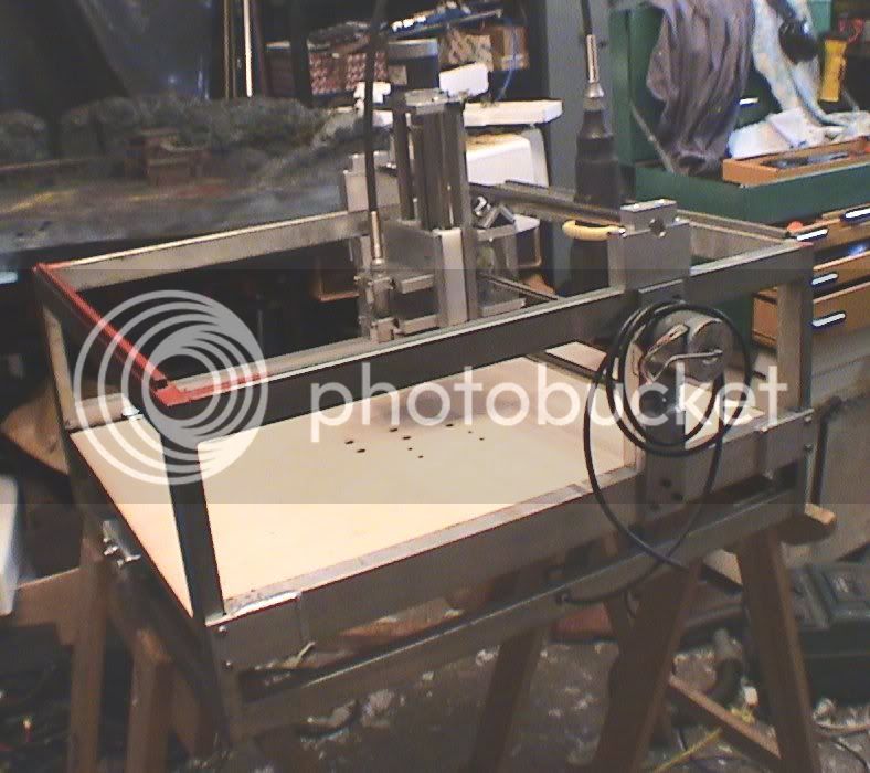
My CNC Solution

Home Model Engine Machinist Forum

Help Support Home Model Engine Machinist Forum:

This site may earn a commission from merchant affiliate links, including eBay, Amazon, and others.

kcmillin

Project of the Month Winner!!!
Project of the Month Winner
Joined
Jan 19, 2010
Messages
1,193
Reaction score
41
Well, as some of you might have caught on by my previous threads, I am very interested and frustrated in buying a CNC machine. I have been looking in every corner of the internet for a ready to go machine, but none of them fit my qualifications. I would like large capacity about 12"X18" and ability to mill aluminum and steel, and all for $2000 or less. This seems like an impossible task.

In my searching I found a lot of CNC routers, but they all have major flaws when it comes to rigidity. Their support rails are usually undersized and unsupported, so flex and vibration would indeed plague these machines, although I am sure they work fine for balsa wood. Also their spindles are questionable. A Dremel, come on... Really?


So, that brings me to my plan.

Ah yes, a crazy plan it is.

For capacity, the Gantry style is it. I am thinking of using a Moving Table style gantry mill, where the Gantry is Fixed, and only used for the X and Z axis, and the table moves back and forth for the Y. ( On Gantry machines the X is on the Bridge, and the Y axis IS the Bridge or table)

OK, my plan is to use four 20mm round SUPPORTED rails mounted to the bottom of the table, with 8 bearing blocks mounted stationary on the base of the machine. The rails would provide a ton of support to the table, making it more rigid. Will I have trouble with four rails and 8 bearings?

Here are the rails.
http://cgi.ebay.com/ws/eBayISAPI.dl...255&ssPageName=STRK:MESINDXX:IT#ht_3883wt_922

Also the table will be made out of either 1" aluminum or 1/2" steel plate with tapped holes everywhere. Please tell me if this is overkill, these are quite expensive. This will be a lot of work so another option is the extruded aluminum rails found on most routers. But I am not sure of their rigidity.

The Frame construction will be 1/2" steel, along with the gantry support. There will be two 20mm supported rails mounted to 1/2" steel. The Z axis will be the same. Should I go thicker?

So far, with electronics but no spindle, I am at about $1300.

Let me know if I am just dreaming here. I have seen machines on u-tube with less structure than this mill steel and aluminum, albeit slowly.

Oh ya, 5/8" ballscrews on all axis also, along with 280oz/in stepper motors. Will 280 be enough? I am most worried about the Z axis strength. I want to keep the spindle options open, 40 - 50 pounds may not be out of the question.

Kel
 
If you want Frame rigidity, think 'inside the square'.

This is how I did the framework for my CNC Router - forget the Dremel, it was just there for testing purposes.
It has a Moving Table - X-Axis - which is mounted on Precision Linear Drawer Slides.

The Y-Axis gantry is fixed rigidly to the Box Framework, unlike the usual way of suspending it up in mid-air.

MicroMill2.jpg


Here is the Article I wrote many years ago for our Model Engineering Society;

CNC on a Zero $ Budget

Last Month, another industrial sized photocopier arrived and was duly dismantled in my workshop, this yielded the usual salvage of Electronics and Mechanical bits'n'pieces which included a rather chunky Stepper Motor. This was the third of these steppers which I have now salvaged and stored for a rainy day.
I don't know wether this was the catalyst, or maybe it was the inspirational time spent at a certain Workshop in Wellington, (thanks Richard). Seeing the CNC 'ShopBot' in action at Weta Workshops sparked a few ideas which triggered the following project, a lightweight CNC Mill/Drill on my usual budget of 'not a lot of money'.

I happened to have a 'box section' steel frame, (ex dumpster), which looked around the right size, three stepper motors, and a heap of other bits from the scrapheap lying around the workshop, so here goes . . .

Research on the Web has given me a few ideas and I've formed a few opinions of my own based on this. Most of the Desktop CNC machines that people have built, use a gantry arrangement to move the X Axis, with the Y & Z Axes attached to it. The commercial ShopBot uses this system. It seems to me that any excess movement in the Gantry would be amplified in both the Y & Z Axes to the detriment of accuracy in all planes. Given that I have the abovementioned steel frame, it lead to the idea of moving the Work Table in the X Axis, which would be attached to the frame itself, so that the other Axes are totally independent. Usually the method of movement is achieved by use of extreeeemely expensive Recirculating Ball Linear Bearings, however this is a Zero Budget Project right?

The last photocopier I stripped, yielded three pairs of heavy duty Drawer Slides which, after modification, turned out to be quite precise in tolerance. These were fitted to the Frame with a piece of Meltica laminated MDF serving as the work table. As rigidity is essential in this machine, I decided to use the Lead Screw as a lightly stressed frame member. I'm using M8x1.25 Stainless Threaded Rod and the tension will help keep it straight. This means that the Lead Screw does not rotate, but the Feed Nut does. A Stepper Motor was coupled via a Toothed Belt to a Toothed Pully which had been internally threaded M8 and arranged on a bracket fixed to the underside of the Table, (see photo). A bit of jiggling & beating with hammers and presto, the X Axis is complete and working.

A short word on the spec's. I'm using 1.25mm pitch Lead Screws coupled directly at 1:1 to the Stepper Motors which rotate 1.8 degrees per step. This gives 160 steps per mm with a theoretical precision of .0065 mm of linear movement per step.
(That's 0.0002559047 of an inch for the metrically challenged).
Theoretical maximum Workspace will be X = 500mm, Y = 380mm, Z = 130mm but this will decrease a little when Limit Switches are fitted. I'm aiming to accommodate 50mm thick material on the Work Table.

As the Y Axis Shafts cannot be positioned until the tool overhang off the Z Axis is determined, the Y Axis Carriage and Z Axis Tool Holder must be constructed first. The Z Axis Slideways are constructed of 15.85mm Hard Chromed Shafting, (ex photocopier), with Sliders made from Ultra High Molecular Weight Poly Ethelyene, (UHMWPE). This plastic was supplied as a free sample from Ludowicki Plastics and was sitting there just waiting to be used for some worthwhile project. A rigid frame was constructed with 10mm aluminium from the scrap bin, Stepper Motor, Lead Screw and Tool Holder Base all fitted up and of course absolutely nothing worked . . .

UHMWPE is a strange beast to work with. My shafting is 15.85mm dia, so I drilled the Sliders out to 16mm in the lathe, mainly because (A), I knew that there would be some flex in the plastic, and (B), a 16mm Drill Bit is the only one I have around this size. The Sliders glided as smooth as silk on their Shafts when tested straight off the lathe, but seized up after a few minutes. After a few days of trying various lubricants and a few choice words I realised that as the drilling took place the Sliders heated up and expanded, giving me the clearances needed and on cooling closed up enough to seize. I had a spare piece of shafting which I flared the end slightly and used as a drift, gently scraping the bores until they ran free again – cold.

So, I started on 1 May and so far I have completed the X Axis and Work Table, the Y Axis Carriage and Z Axis assembly and I'm half way through building the Stepper Driver/Translator Electronics. I now need to mount the Y Axis Slideways to the Frame, build my version of Linear Bearings, (using Skateboard Bearings & Aluminium Angle), finish the Drive Electronics, find and reprogram my old Pentium 166 Computer, do the Wiring and throw the whole lot together and make it run. This is of course after I learn G-Code, CAD, CAM and CNC Control to understand how to make it all work. And then there's a Phantom Loco waiting for me in the workshop . . . somewhere . . . .


Murray McKenzie
 
Thanks for the input Murray. I like your resourcefulness. I like the cost effective methods and materials, but I will have to pay for rigidity. I hope to come out with an actual CNC mill with the capabilities of a small milling machine and the capacity of a Bridgport.

I am trying to decide what to use for a mill table. Steel or Aluminum. I am thinking of between 1" and 2" thick Aluminum Jig plate 12" x 18" long. Is this way too thick, or not thick enough? Should I go with steel? There will be four rails mounted to the bottom of the table so this should help with rigidity. Remember I will be using this like a real milling machine.

I don't want to spend too much on raw materiels if I don't have to. The thicker I make the structure the more expensive it gets. At what point does adding more metal become irrelevant.

Please, any thoughts welcome.

Kel
 
I have most of the mechanical parts to make a ~50"X, ~24"Y, ~8"Z mill router, but space has run out. What will you use for a base? If you're building the frame from steel how will you level the frame to ensure flatness. Occasionally I look for cheap surface plates and I once saw a 72" x 24" x 4 or 6" granite for next to nothing but it was 2000 miles away. I was thinking the local granite counter top guy or (shudder) head stone maker.

Greg
 
Greg, To keep things flat I can use my mill to face mill the top surface of a 10"x15" or so channel Iron, then the 8 pillow blocks, ball nut, and Gantry will all bolt onto that surface. I can then use shims to tram the whole works. It will look similar to a CNC router, just beefier. I am hoping to bolt everything together, as I don't have a welder. If all els fails I live a block away from one of the largest machine shops in the country, I am sure they can make a piece of steel flat.

Kel
 
G,day Kel, "Wow" what a task, should be a very rewarding challenge upon completion.
I had a look at the linear bearings you had in mind. I have a supplier that I use also on ebay which I thought you might be interested in and also may be able to save some $$$. worth a look.


http://stores.ebay.com/linearmotionbearings

Cheers Baz.
 
Thanks for the Link Baz. I sent the seller a question if I could get a custom kit, as many of the kits available do not meet, or exceed my requirements. I will be awaiting a response.

How hard is it on a band saw to cut these shafts, or the ballscrews for that matter. I understand they are case hardened, can my little band saw blade handle it?

Kel

 
I use linear bearings very similar to those in some of the machines I've designed for my employer. One of them being a pneumatic counter sink machine. I purchased them from McMasters I ordered the rails in the lengths I needed and then the bearing blocks. One of the machines have been in service foe 7 years now with no trouble with the machine at all. Its run 8 to 10 hours every day. So they should hold up good for a cnc build.
 
Thanks for the great info Doc.

I have some questions regarding the parameters of your use of these rails.

Do you recall how big the rail was you used? Also what type of load were they under? and How many rails did you use?

I am planning on using four 20mm rails 700mm long placed 3.4 inches apart on center with two bearing blocks per rail. I might have to offset the two middle rails to find room for the ball nut. They will be bolted to a 12 x 24 plate of aluminum or steel. This will make up the table.

Kel
 
That link is great Greg.

4 seems a bit crowded too. 4 rails to support a 12" wide table. Maybe too much, but I don't want to under do it.

Here is the table material.
http://www.speedymetals.com/pc-2931-8362-1-aluminum-cast-tool-jig-plate.aspx

It has a flatness tolerance of .005", which would make flatness less of an issue, and I can always use the machine itself to flatten the surface to higher tolerances.

Kel
 
G'day Kel,

No drama's for the link to the linear bearings. I have used this same guy several times and he always has supplied ball screws and linear bearings to suit the length needed, He also has an end machining service but i guess this takes the fun out of it. Yes the linear guides are case hardened, I have always used my lathe to part them to length using slow speed, a heavy hand with coolant, then machined the bearing dia's with a ceramic insert . I reckon you will be able to cut them with a band saw as the case hardening is only approx 1mm thick, but you may need a spare blade. I wouldn't recommend a friction saw coz you may jeopardize the hardness.

Good luck mate, please keep us posted on the build.

Baz.
 
I would agree that four rails is overkill, it could cause you grief with binding if everything isn't exactly aligned. Two rails spaced as far apart as is possible will work fine, I would think. Keep the linear bearings as far apart as possible also, but keep in mind that the rails will need to be long enough to give you enough travel.

The ball screw should ideally be centered between the two rails to keep "skewing" to a minimum.

Have you considered adding "webbing" to the bottom of the table? It could be just bolted in place or welded and the table machined flat. You may be able to use thinner material for the table then, and it would be lighter reducing the load on the axis drive.

Another option on a gantry type machine would be to have the table fixed and have the "bridge" travel, but that creates other issues. The advantage to this would be a smaller machine footprint, but not much else in my opinion. One commercial machine I had seen several years ago used both methods and would move the table in one direction and the bridge the other, giving rapid travels in the 1400 in/min range. That would give you a real challenge!

As far as cutting the rails, I have used an abrasive saw to cut them, and faced the ends in the lathe, or possibly use your bench grinder to get through the case and part them off. I have parted them off in the lathe also; but I had use of a lathe with a big enough spindle to pass the rail through and could work close to the chuck.

Just a few thoughts.

Kevin
 
The counter sink machine I designed had 2 rails for x travel and 2 rails for y travel and then z was an just a pneumatic cylinder mounted in a saddle. The only stress put on the rails is the weight as every thing hangs from these rails they are above the table like a gantry mill. They position to the counter sink location and the air cylinder fires and drives a pneumatic air tool that is mounted to it into the part. It does thousands of holes a day some times. I would take a picture of it but I would get into some big trouble as it is now their design and I'm sure they don't want their competitors seeing any of their equipment. Ant way those rails work excellent for this machine if I remember right the rails were 1 inch dia but they were also 3 feet long. I would venture to say that the shorter and smaller dia would be just as good.
 
Thanks for the input Kevin and Doc.

I think I will be able to get away without cutting the rails length. They will hand past the table about an inch on either side, but this will be OK. I will be able to then get my desired travel of 18".

OK, my plan is changing slightly. I think two rails should work.

Also, the materials are adding up in cost.

The aluminum plate 12"x24"x 1" thick is $200. I could save $50 by going with 3/4". There will be 2 supported rails attached to the bottom about 10" apart. I am pretty sure 1" thick is going to be strong enough, this is tooling plate after all, but at what point does the machine cease to be a better machine and start being a more expensive one. I really don't know, I just keep thinking BIG BIG BIG.. I could also make it from four 6" wide pieces 12" long of 1.25" thick cast iron to give me the 12x24 table. this would be 4 times as heavy as aluminum, and the same price. What would the problems be with mounting four blocks to these rails. This plan would make machining of the table to be done "In House" Since 12x6 is within the capacity of my mill.


My Idea for the frame is 10" x 3" steel square tubing. 24" long for the base, and between 18" and 24" long pieces of the same tube for the upright gantry supports and a 2"x 8" tube to connect the two uprights and provide support for the rails. These will be bolted together, but they will have some welding work to create spots for the bolts.

Could I get away with using channel instead of tubing? Again, the material list is adding up in price, I will pay it If it is needed, I just don't want to go overboard and over budget.

Thanks again for your help in coming up with a good plan. I am going to have to get some Maple Syrup for all the waffling I have been doing. :big:

Kel
 
MMMmmmmm!!!!! Waffles! ;D

Sorry, couldn't resist.

Between the electrics and the hardware the cost of a CNC project can grow very fast. It is still amazing how much more accessible CNC is to the hobbiest than it was just a couple years ago!
 
kvom said:
What are you proposing as far as attaching work to the table? That might help determine what material to use.


I want to keep my mounting options open. There will be either a bunch of tapped holes or T-slots. There will be about 6-8 inches of height between the table surface and the bottom of the gantry. I was thinking using a vise for most applications, possible a two piece vice to keep a low profile. I will most likely be making fixtures for odd projects. Basically the same thing I do now with my mill table.

The aluminum Jig plate is made to a decently high tolerance + - .005" on the width,and is stressproof so it wont warp, but it is about twice the price of steel, and the same price as cast iron.

The aluminum plate weighs about 30 pounds, while the cast iron will weigh about 100 pounds. I am not sure what the rails are rated at, I plan on using 280oz/in stepper motors.

Kel
 
With 12"x24" 1/2" steel and 1/2" aluminum plate the price would be about the same as aluminum. Plus I would have to outsource the machining of the steel plate to get it flat. I was also thinking I would machine two slots for the rails to go into to provide side support to the rails, this will be cheaper to get done than steel.

Any thoughts on extruded aluminum tables, like those used in CNC routers.

Kel
 

Latest posts

Back
Top