Locking hubs on flywheels

Home Model Engine Machinist Forum

Help Support Home Model Engine Machinist Forum:

This site may earn a commission from merchant affiliate links, including eBay, Amazon, and others.

Brian Rupnow

Design Engineer
Project of the Month Winner
Joined
May 23, 2008
Messages
15,259
Reaction score
8,544
Location
Barrie, Ontario, Canada
When I built the flywheels for my Kerzel engine, I drilled and tapped each hub 3 places at 120 degrees for set screws, to hold them to the crankshaft. I believe it was Tel who pointed out that this was incorrect. Two setscrews at 90 degrees apart are far better and will lock things more securely. Now on a steam engine, I would probably have been okay with that, because generaly you will have the flywheels on and off a maximum of about 5 times during the build.---BUT---On this I.C. engine, I have been loosening those screws off and turning the flywheels to reposition them to adjust the way the counterweight arms pivotted and for various and sundry other reasons, to the point where my crankshaft is all scored up, and the set screws are all getting worn to the point where the allen wrench slips in them.--And the flywheels are seizing onto the shaft, becoming so frozen in place that they are very difficult to adjust rotationally. Since I have to pull the crankshaft out to install the roller bearings I have ordered, I thought this would be a good time to design and build some other type of locking mechanism for the flywheel hubs. Luckily, the flywheel hubs are 3/4" o.d. with a 3/8" bore, so I have some meat to work with. My plan is to open the bores out to 1/2" dia. and insert new steel locking type hubs into them. This is the drawing of what I plan to do---and for all you eagle eyes out there who will want to tell me that the head on a #5-40 shcs won't fit into a 3/16" c'bore, I know that. Its just that I didn't have room to make the extended portion of the hubs longer than 1/4", and I do have a 3/16" 2-flute milling cutter, so I planned on turning the heads down to 0.180" diameter.
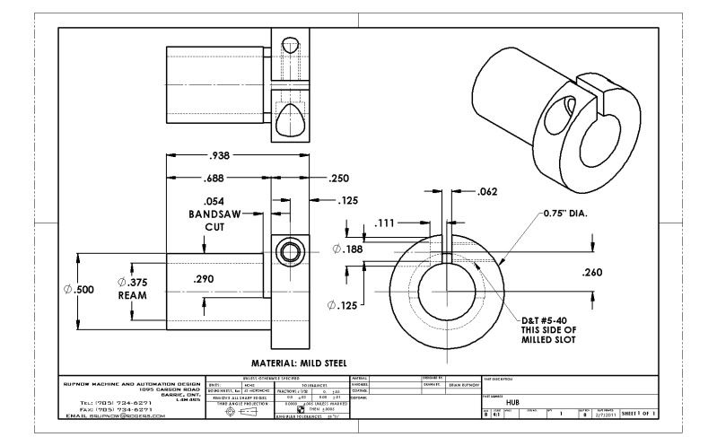
HUB-2.jpg


View attachment HUB.PDF
 
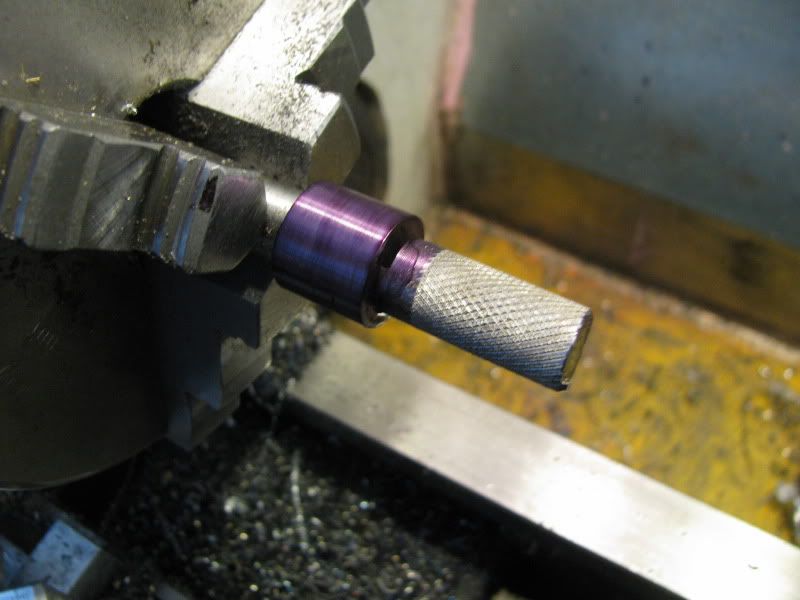
I happen to have a 12 foot length of "mystery metal" which is 7/8" diameter, and a scaly black outer coating. Its probably hot rolled, but its a little harder to machine than the cold rolled stock I buy.---Oh well, ya work with what you have. I cut a peice about 6" long and turned it down with a carbide to 3/4" dia, as per drawing. Then I turned one end down to 1/2", as per drawing. Then I turned the other end down, and damn, wouldn't you know it--When I miked it, it came in at 0.495" diameter. Oh well, you can put metal back on---thats why one end is knurled. Knurling displaces metal, and brought the diameter back up to about .502" dia.
HUB--SQUEEZETYPE012-1.jpg
 
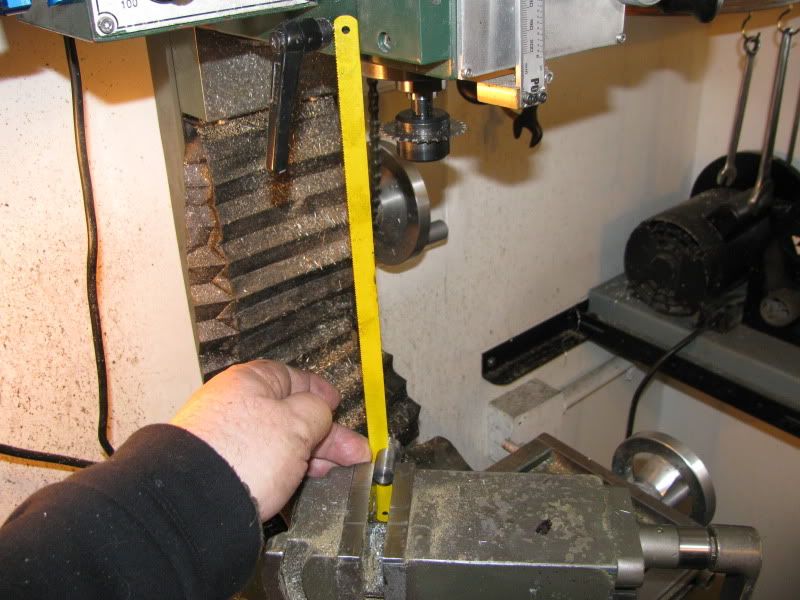
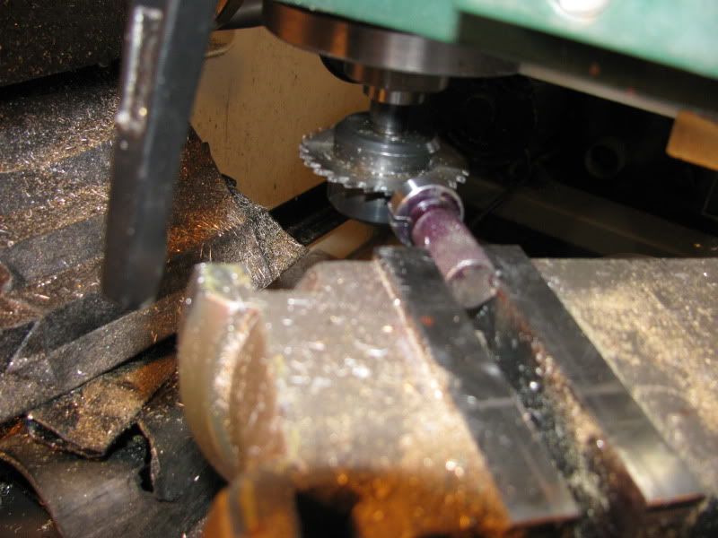
I sawcut slightly more than half way through the diameter with my bandsaw---It doesn't show, and its not critical. That cut is what lets the two sides of the hub pull in and grip the shaft when the screw is tightened. In this picture, I'm setting up in the mill to use a slitting saw to make the other cut which runs down to the center bore. The yellow hacksaw blade is held in place in the bandsaw cut and lets me set the part up with the sawcut in the vertical plane. Its the only way I know of to do that, and it works.
HUB--SQUEEZETYPE005-1.jpg
 
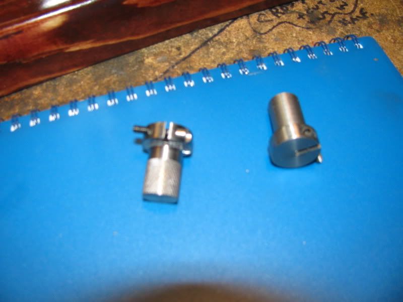
This rather blurry picture shows the two hubs finished except for the center bore. I don't like wobbly flywheels, so they will be loctited into the flywheel hubs and let set for 24 hours, then drilled and reamed in the chuck. (The one with no knurling ended up being a "push fit". The one with the knurling ended up being a BFH fit. (Big Friggin Hammer).
HUB--SQUEEZETYPE006.jpg
 
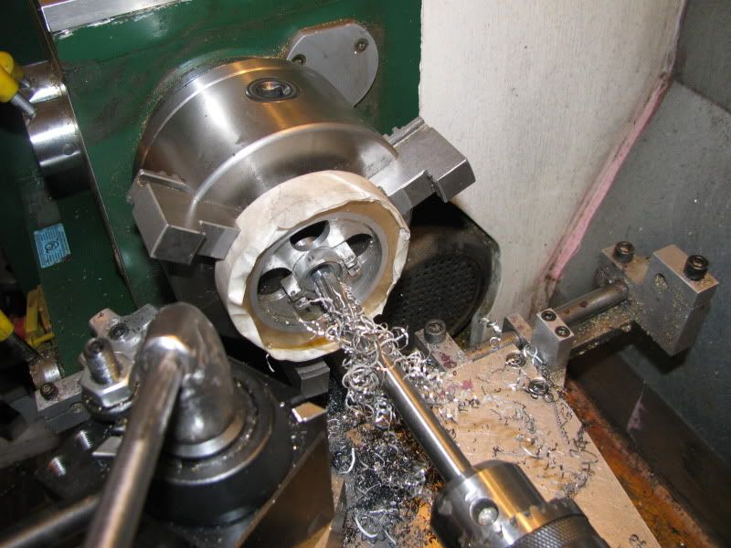
This is one of the flywheels being drilled out and reamed to 1/2" diameter. A purist would have bored them, but I'm not a purist, and I do have a 1/2" reamer. You will see that I have a couple of layers of masking tape around the o.d. of the flywheels, to protect them from chuck scars.
HUB--SQUEEZETYPE007.jpg
 
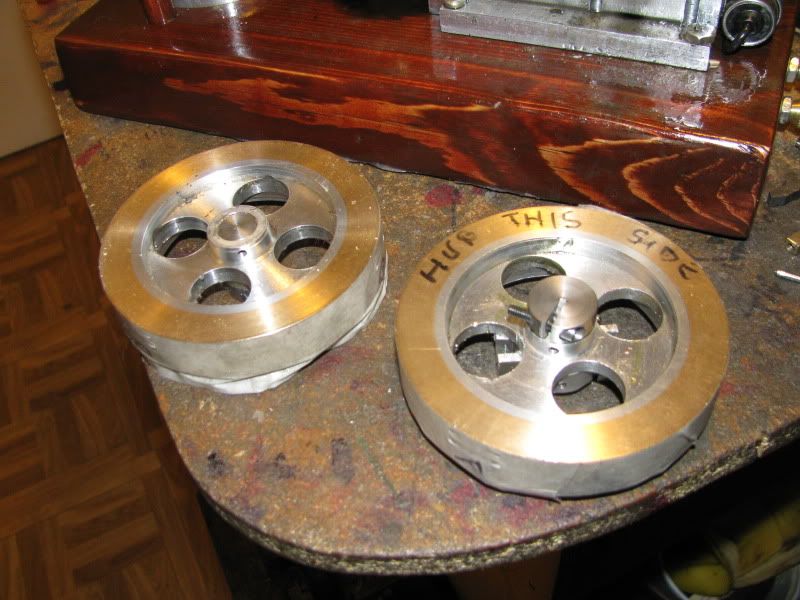
And here we have the two little beauties, new hubs loctited into place. I will put the new center bores in tomorrow.
HUB--SQUEEZETYPE009-1.jpg
 
Rick--I knew I'd seen that post, but I couldn't find it today!!! I had to make the changes to my machine today, so I figured I might as well take a few pictures as I went along. My roller bearings were supposed to be in today, but of course they're not. I soon have to get off my duff, (or at least out of my machine shop) and promote some engineering/design work. I've been coasting ever since Christmas, but that doesn't bring much money in.
 
Hi Brian, I'm glad I could help out.

Drumming up some paying work sounds like a good idea.

I always say; "Cash makes no enemies" Thm:

-MB
 
Brian,
That's a neat fix for the problem of set screws scoring a shaft. If you're ever in that position again and you don't have room for the hub or meat on the flywheel try using brass tipped set screws. They seem to hold pretty well on low rpm steam engines but I don't know how they hold up at higher rpms.

Anyone tried them on IC engines?

Phil
 
Brian,

I had a lot of the same problems with flywheels getting galled up on the crankshaft, & set screws getting messed up. Also the flywheels would get loose after a few hrs. of run time & my key ways would get hammered out. Now I install 2 degree tapered keys & have great success, I also hate flywheels that wobble! The tapered keys really lock the flywheels on & eliminate the wobble induced from set screws.

Mike N
 
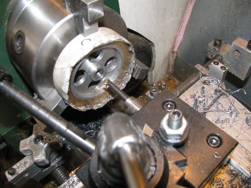
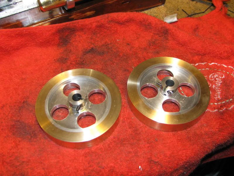
Well, I uhmmmm---I lied. I wasn't going to bore the bore?? but I've has enough problems with non concentricity with this engine, that I decided "Why take the chance??"--Even old dogs can learn!!! I center drilled them with a center drill or c'sink (depending on what you call them) and drilled through with a 5/16" drill. Then I found one lonesome boring tool that was long enough and small enough in diameter to fit through the hole. I bored it out to 11/32" dia., then finishd it off with my 3/8" reamer.
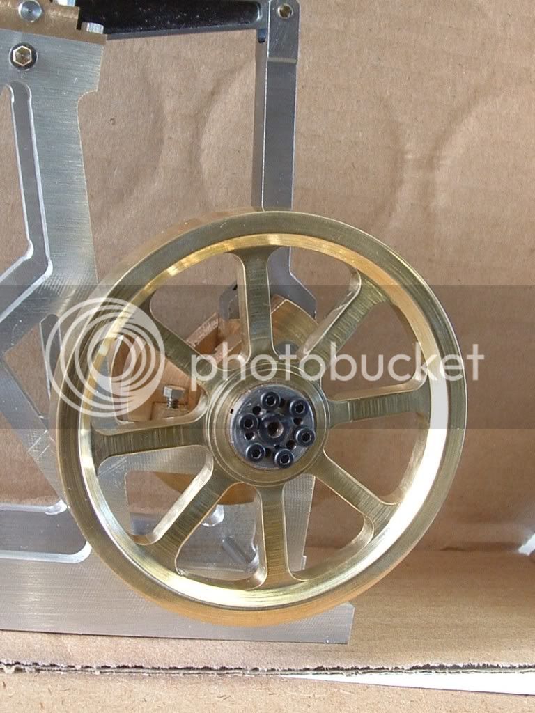
flywheelhubsfinished001.jpg
 

Latest posts

Back
Top