- Joined
- Jun 4, 2008
- Messages
- 3,294
- Reaction score
- 636
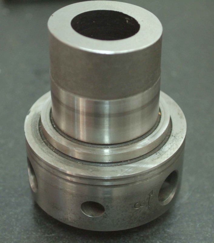
I would like to be able to move a workpiece between the lathe and rotab while keeping it in the same chuck. To that end I acquired a cutoff D1-3 spindle nose from a Monarch 10EE that was being parted out:

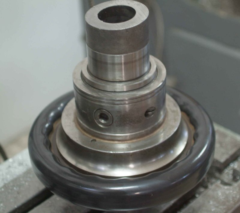
I also have found a set of cams and screws, so I can contemplate beginning the project. The rotab is a 8" PhaseII with a MT3 center hole. My thought is to make a mounting plate that will hold the spindle nose and locate on the center hole.
The cutoff portion of the spindle is 2-3/8" in diameter, and the ground bearing surface is in good condition.
My plan is as follows. I am posting this here to gather opinions on how it might be done better.
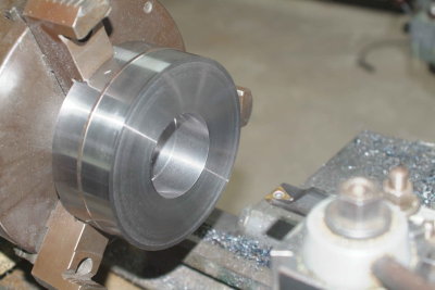
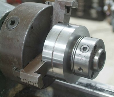
First, I will cut off the rest of the shaft leaving approximately 1" of spindle bearing surface. The mounting plate needs to be thicker than the length of the shaft. This plate would be ~4-5" in diameter and made of steel. I would turn it as flat as possible on my lathe and then bore a through hole to be use for locating on the rotab (call this diameter D1). Then I would widen this bore to 2-3/8" and deep enough to accommodate the spindle in a press or sliding fit. Next, I would surface grind the opposite side (that sits on the rotab) to ensure that it is parallel to the bored side.
For the table locator, I am thinking of starting with a MT3 carbon steel dead center. With the rotab center on the mill and the dead center in the hole. I would mill the protruding part to a cylinder of diameter D1 to match the spindle moun ting plate. I would actually do this operation first and bore the plate for a sliding fit.
If this all comes together, then mounting to the rotab would be straightforward: place the locating rod in the center hole and slide the plate/spindle over it, then clamp the plate to the table. Centering the rotab to the spindle could be done either using the rotab center hole or the spindle nose itself.
I would hope to get accuracy of better than .001" this way.
Thoughts?


![DreamPlan Home Design and Landscaping Software Free for Windows [PC Download]](https://m.media-amazon.com/images/I/51kvZH2dVLL._SL500_.jpg)


![MeshMagic 3D Free 3D Modeling Software [Download]](https://m.media-amazon.com/images/I/B1U+p8ewjGS._SL500_.png)

![TurboCAD 2020 Designer [PC Download]](https://m.media-amazon.com/images/I/51UKfAHH1LL._SL500_.jpg)


