- Joined
- Jan 19, 2010
- Messages
- 1,193
- Reaction score
- 41
Here is a collection of engines I had made a few years ago. All I had was a Blackberry to look at tiny pictures of steam engines. No Computer :wall:
The first two are my attempts at understanding the slide valve.
Here is the "Purple" (No laughing) :big: This guy has over 2500 hours on it, it was painted while running (don't ask) it can run on a breath of air and, if properly regulated, can run as slow as 50 rpm. I estimate to pressure to be about 1 half psi to get 50rpm.
This is the second generation of my slide valve engines, optimistically called "Kelly's #1" because I had made plans for it which I have posted in the downloads section. I decided to try a Stephenson reversing link out since most of the engines I seen pictures of were for small steam boats.
The ticking is a loose piston rod pin.
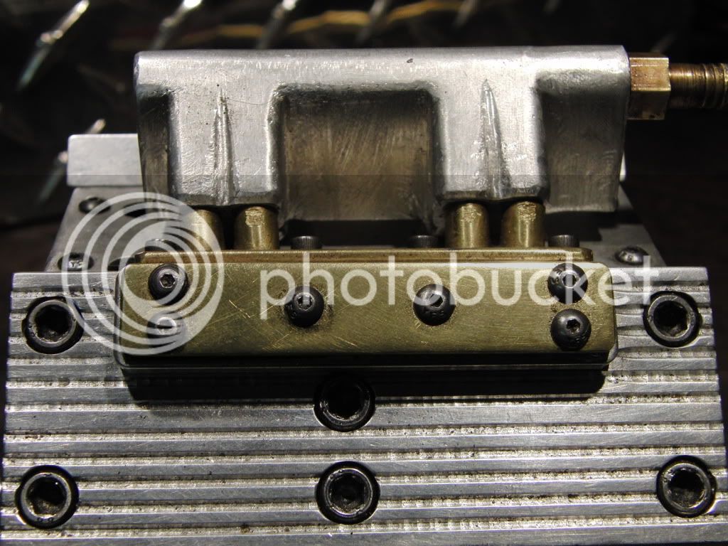
This next engine is a V-4 cam operated push rod valve design. There is two valves per cylinder, one intake and one exhaust. This way the engine can run forward and reverse. I had also drilled holes for the exhaust on the side, this dramatically increased its speed. It will run up to 5000 rpm on 120psi.
The cam operates reversed from the crank. I only realized at the end that I had to get creative with the intake. It works because the cam lobe for one cylinder's intake valve is the exhaust lobe for the opposing cylinder. It made for some real head scratchin to figure out what was going on. :wall: The valves are piston type, the cam pushed them up the expose the hole, the springs on top close them. The brass bits on top of the heads hold the springs down.
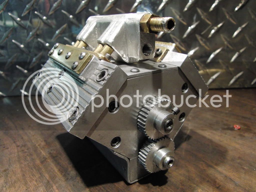
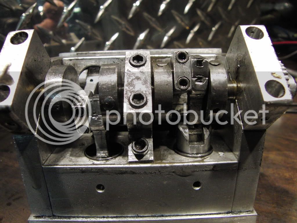
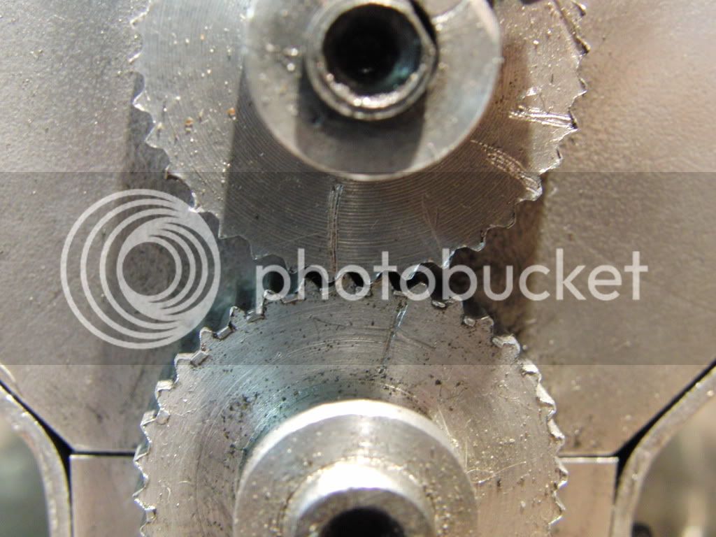
OK, now I know all of you will laugh at this next pic. It is a set of gears I made on my rotary table. Using a tool bit I ground down to an approximate angle by eye. They are not engineered in any way. But hey, they spin 5 G's!
And here is the video.
Enjoy.
Kel
The first two are my attempts at understanding the slide valve.
Here is the "Purple" (No laughing) :big: This guy has over 2500 hours on it, it was painted while running (don't ask) it can run on a breath of air and, if properly regulated, can run as slow as 50 rpm. I estimate to pressure to be about 1 half psi to get 50rpm.

This is the second generation of my slide valve engines, optimistically called "Kelly's #1" because I had made plans for it which I have posted in the downloads section. I decided to try a Stephenson reversing link out since most of the engines I seen pictures of were for small steam boats.
The ticking is a loose piston rod pin.

This next engine is a V-4 cam operated push rod valve design. There is two valves per cylinder, one intake and one exhaust. This way the engine can run forward and reverse. I had also drilled holes for the exhaust on the side, this dramatically increased its speed. It will run up to 5000 rpm on 120psi.
The cam operates reversed from the crank. I only realized at the end that I had to get creative with the intake. It works because the cam lobe for one cylinder's intake valve is the exhaust lobe for the opposing cylinder. It made for some real head scratchin to figure out what was going on. :wall: The valves are piston type, the cam pushed them up the expose the hole, the springs on top close them. The brass bits on top of the heads hold the springs down.


OK, now I know all of you will laugh at this next pic. It is a set of gears I made on my rotary table. Using a tool bit I ground down to an approximate angle by eye. They are not engineered in any way. But hey, they spin 5 G's!

And here is the video.

Enjoy.
Kel


