Jim builds his second v-8

Home Model Engine Machinist Forum

Help Support Home Model Engine Machinist Forum:

This site may earn a commission from merchant affiliate links, including eBay, Amazon, and others.
awJCKDup said:
Jpeter, I was just looking at the pic of the timing gears being milled---What size endmill was Used?
Thanks John
If you're asking about the gear cut from 1/16 plate I rough cut first with a 1/8 end mill then followed up with a 1/16 end mill. I don't recall what I used on the spokes. The same sequence was used on the pinion.
Lakc said:
I would think along the lines of how much water can you ultimately move, then figgure out how much space is needed to not impede the flow.

Full size practice of late only keeps water around the top 25% or so of the cylinder for iron liners in a aluminum block. At our scales, we need all that just for head bolt thread engagement. I would jacket the rest as deep as I dared, but most of the convection will be from liner--deck--coolant rather then liner--coolant.
For a long time was thinking of pocketing in from the side for the waterjacket, then putting a cover over the opening. Then, like what you're saying, I got thinking the water needs to be up near the top of the cylinder. Cutting in from the side below the head bolts would keep the jacket and water well below the top and not cool the cylinders up where they need to be cooled. I machined my sleeves with a 1/16 flange on top. I think I'll use half that, 1/32, for water space. My sleeves have 1/16 walls. I might turn half that away too. Between the two I'll have a 1/16 space for water. What do you think?
 
Yep, that's what I was curious about---Thanks and keep up the good work.
John
 
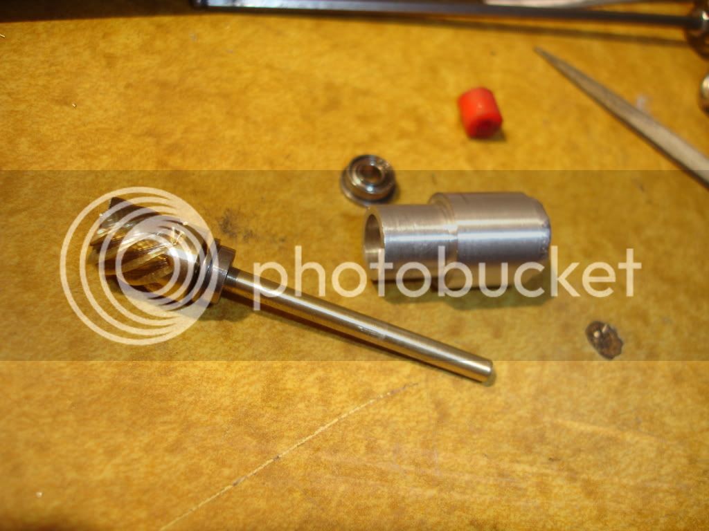
Got started again. Had a google redirect virus on my laptop. Really hosed it up. It got me sidetracked for a while. Last couple of days I made some parts for the distributor. Here's a picture of the stem.
DSC02271.jpg

 
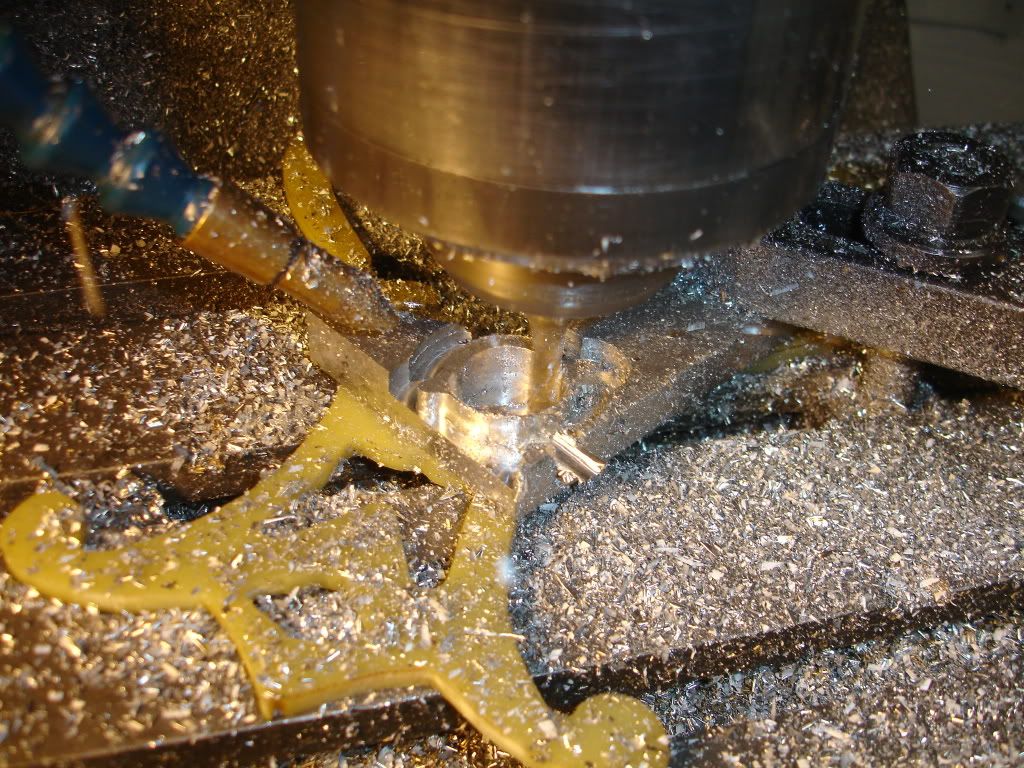
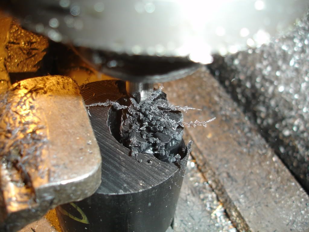
Next step was to make the housing. I milled most of it. Here's a picture of the base being milled to shape from the bottom. Its got ears for bolting down the cap so I had to mill it in two stages. I used a 1/4 dia, 4 flute cutter.
DSC02272.jpg


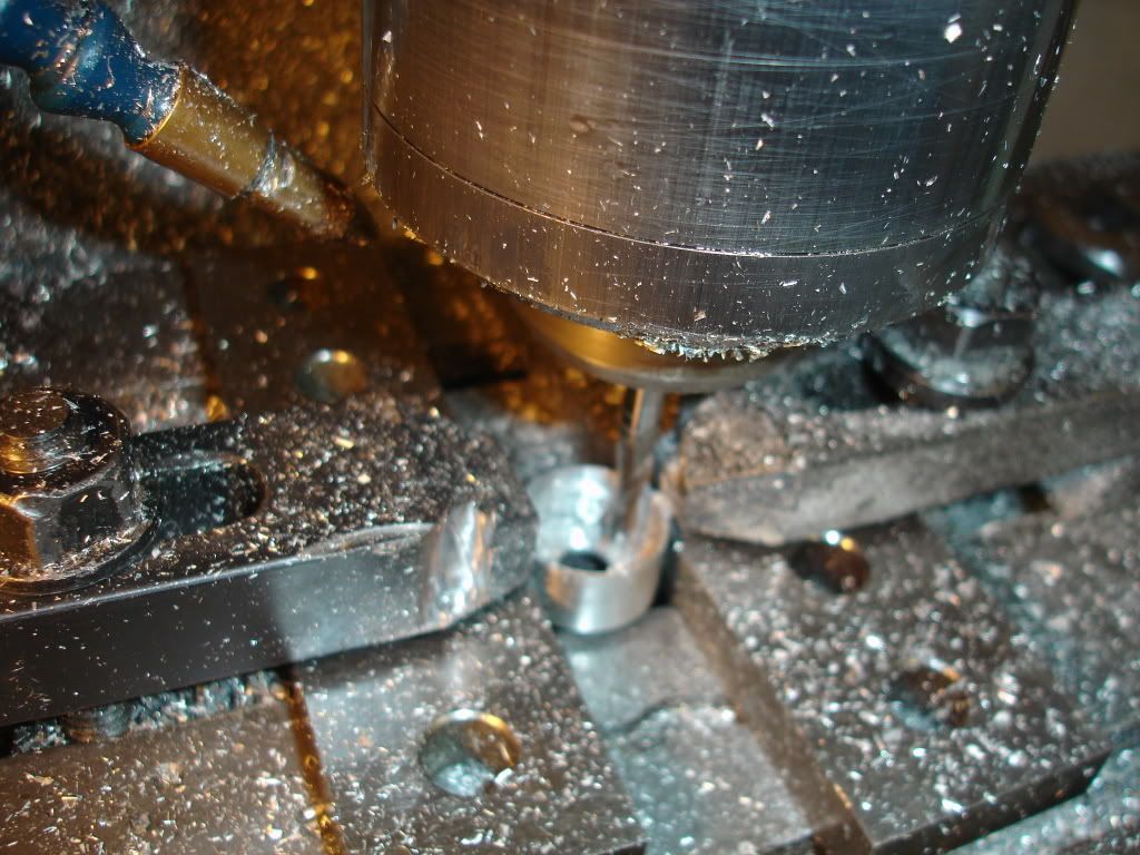
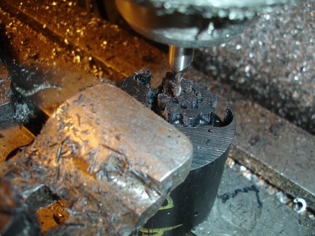
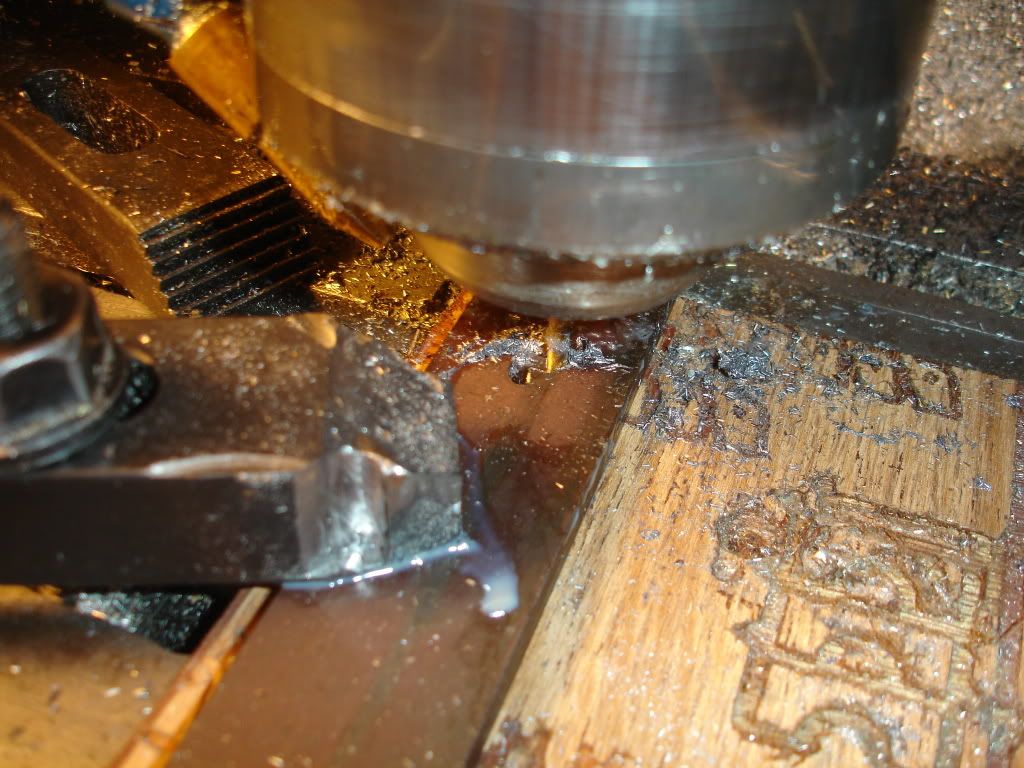
Here's another picture of the milling out of the top side. It's being held down by the ears. I had a crash here. I didn't allow for the height of the clamp and ran the cutter into the clamp. Broke the cutter in half and almost milled the clamp in half. The cutter was double ended. Now I have two single ended cutters. The cutter in the picture is not the same one but the clamp is. Notice the gouge in the clamp.
DSC02273.jpg
 
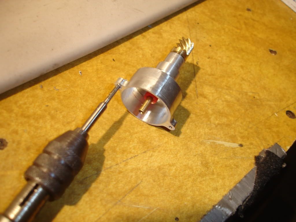
Well, I got the distributor stem and base pressed together. The tap is 2-56.
Everything seems to fit well. I coated the parts with locktite before the pressing.
DSC02277.jpg
 
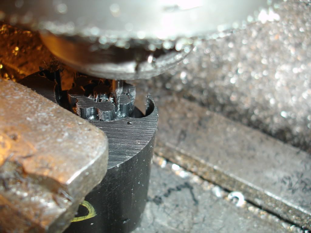
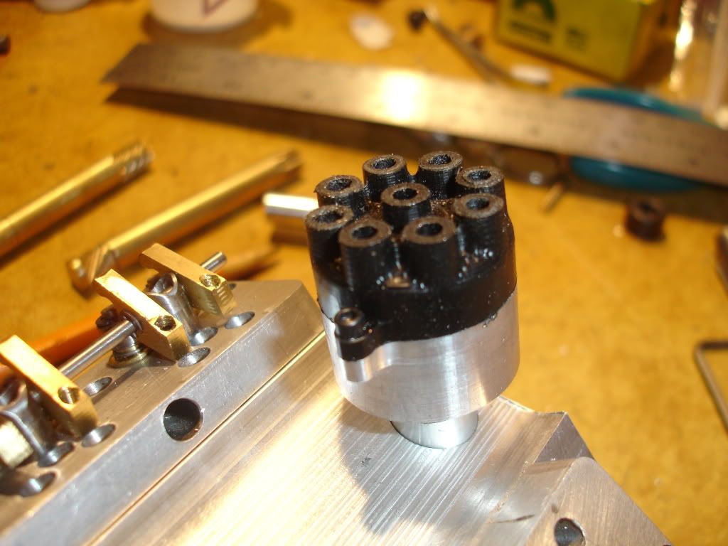
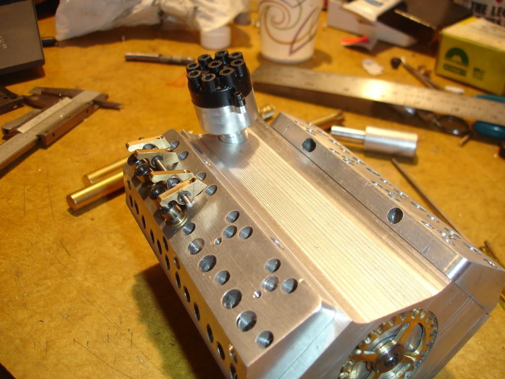
Got started on the cap. I used the same program I used on the last 1 inch distributor I made. Some time ago I picked up a block of Delrin. I'm machining the cap from this black Delrin. It machines well. I contoured the perimeter using a 3/16 flat end mill, roughed the top with an 1/8 ball end mill and finished it with a 1/16 ball end mill. When milling with bits as small as 1/16 I over speed the spindle by running the VFD up to 80. It seems to help.

DSC02274.jpg


DSC02275.jpg


DSC02276.jpg
 
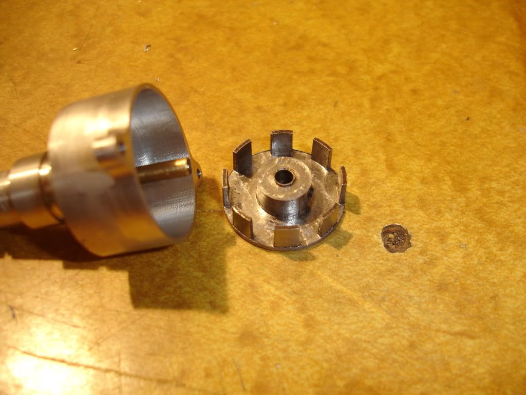
The distributor needs a steel shutter for rotating the spark. The shutter also controls the endplay in the shaft. Here I'm machining the shutter from a piece of 1/4 inch steel plate. Gotta go slow when machining settl with small tools. I'm feeding at a rate of 1 inch per minute. If I remember it's cutting multipal passes 0.1 deep. Interestlingly, the cam program created a glitch by substituting a g3 word when it should have been g2. This isn't the first time this has happened. Good thing Mach 3 has the tool path screen. I've found if the tool path screen doesn't look right I better be checking the program.

DSC02280.jpg


Here's the finished product. The shaft is 3mm dia. Why the odd size, I had the bearings.

DSC02283.jpg


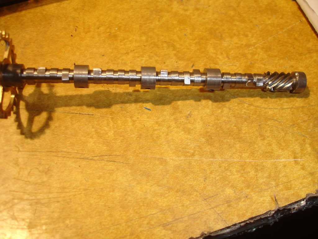
Here's a pic of the cam with the gears attached and milled.

DSC02282.jpg


GDay All,

I have a really silly question to ask.

Should the distributor/cam gear ratio be 1:1 or should it be 2:1? Or to put it another way, should the distributor rotate at crank speed or cam speed?

The old grey matter is getting a bit fuzzy these days.

jpeter, I have been watching your progress for a while now and I am very impressed with your work. I'm looking forward to the completion of this excellent engine and I'm hoping that one day I will be able to produce something like this also.

Keep up the good work Thm:
 
Trumpy, the ratio is 1:1. The distributor turns the same speed as the cam. Certain models have the distributor attached directly to the cam. The cam turns half the speed of the crank, 2:1.
Thanks for the fine comments.
 
GDay All,

jpeter, thanks for that. I was thinking about how much easier it would be to use a hall effect sensor, reading the crank position as opposed to setting up a distributor as you have done, and for some reason I confused myself, I just couldn't remember what speed the distributor should be running at.

My biggest issue is how scary it is to cut the drive gears for the cam/distributor as you have done.

Any chance of sharing the g-code you used to cut them? I know it won't fit my setup, but I might be able to get a better understanding of how to cut them.

 
trumpy81 said:
GDay All,

jpeter, thanks for that. I was thinking about how much easier it would be to use a hall effect sensor, reading the crank position as opposed to setting up a distributor as you have done,
Hi, even with a hall sensor you would still nedd to differentiate which one of the eight cylinders is firing at any one time, so the need for a distributor is still present, hope this helps
 
Chaffe said:
Hi, even with a hall sensor you would still nedd to differentiate which one of the eight cylinders is firing at any one time, so the need for a distributor is still present, hope this helps

I should have mentioned multiple coils etc. Of course that is not very practical or cost effective. I am simply exploring ways to achieve the same thing.

Using Glow Plugs would be a solution but then you'd have to maintain a fairly high idle speed to keep them lit.

I guess I will just have to cut those gears :big:
 
Regarding the gears, miter gears I think are the most commonly used gears for driving the distributor. I just wanted to be different. Firing 8 different coils would create its own set of problems such as how to find room for 8 different hall effect switches in a 1 inch diameter distributor.
As simple as it seems hall effect switched electronic ignitions are not all that trouble free either. They come with their own set of problems, much having to do with having to arrange the switching device so close to the high tension part of the distributor. A 1 inch dia distributor provides such a small space. You've got a cap and rotor, magnets shutter for timing, hall sensor, wires resistors zener diodes, etc, all in a small pill bottle sized space only 1 inch tall. And besides all that it, what with sparks jumping and the engine running right near by it gets hot as hell. Do a search on hall effect ignitions and you find em not all that easy to keep workn'.
Thanks for the question. It provided me a chance to spout a little about a troublesome issue.
 
Here's th gear cutting code. Keep in mind, the rotary axis is Y and Y1 on my machine means 1 full turn. As an example, Y.5 translates to 1/2 turn of the rotary axis. Most mill define the rotary axis as A. In my case I unplug the y motor and plug the cables into the rotary drive. After the program completes I then need to reset y to zero before restarting for the next tooth. I'd make the reset to zero in code. Iif I knew how I would. I'd also like to know how to program the code so it'd run 8 times then quit.
I know, clear as mud.

code:
g90 g1f.5
g0z.1
x0
z0
y0
g1z-.02
x-.5y-.5
g0z.1
x0y-.1
z0y0
g1f1
g0z.1
x0
z0y0
g1z-.06
x-.5y-.5

g0z.1
x0y-.1
z0y0

g1f1
g0z.1
x0
z0y0
g1z-.081
x-.5y-.5

g0z.1
x0y.125

z0

m30
%
 
GDay All,

jpeter, thanks for sharing the code. I was expecting something really complex but it turns out its not that hard at all.

I've rewritten your code to cut 8 teeth non stop then exit, well at least I hope I have :big:

I've added the files to this post.

Use the un-commented file for a TEST run first. Let me know if you find any errors with it. I can't test it here because it's set up for your machine.

It shouldn't be too hard to rewrite it to suit my machine setup though, again, thank you! :bow:

View attachment 45deg Helix Gear - Commented.nc

View attachment 45deg Helix Gear - Un-Commented.nc
 
Hey Trumpy, thanks for the code. If I was gonna do it again though I think I'd use g91 more. By using g91 I could cut all 8 teeth by just copying the code and pasting it 8 times. My wish though is to learn how to add a for-next loop or to increment a variable to run the loop 8 times and then end the program. There's got to be a way.


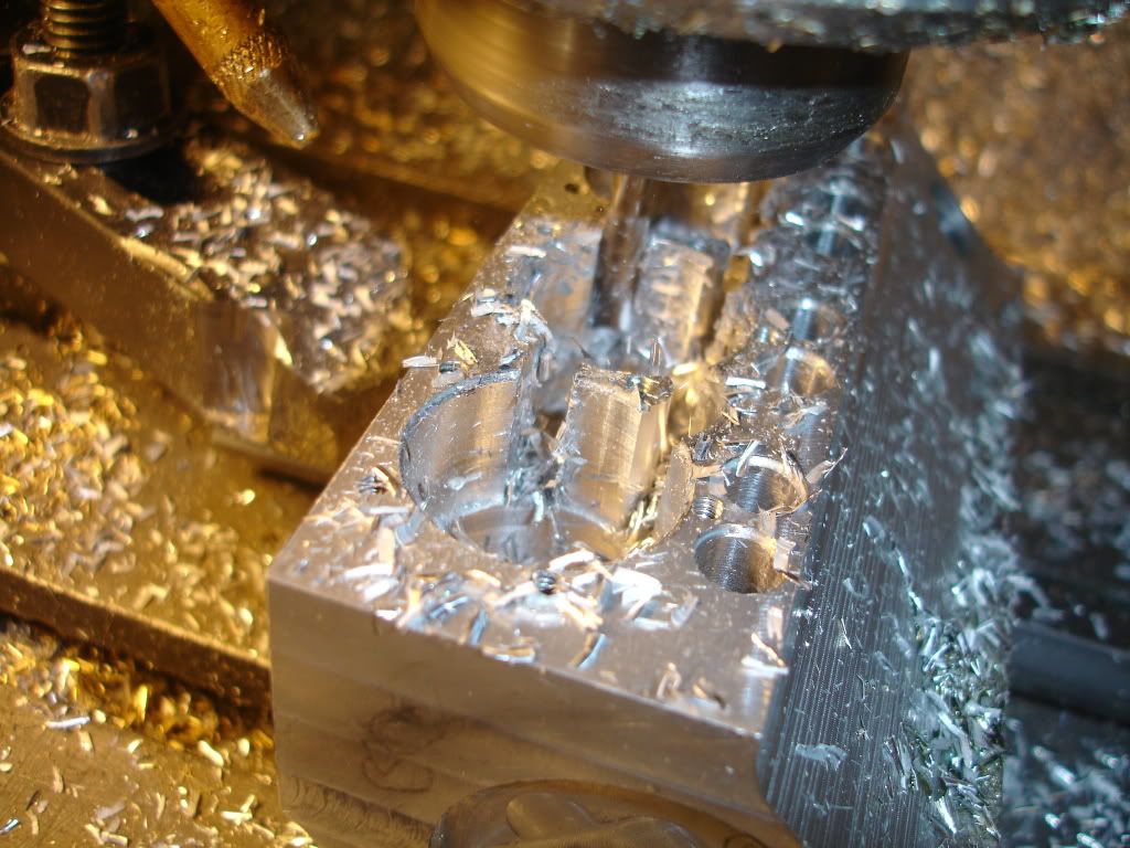
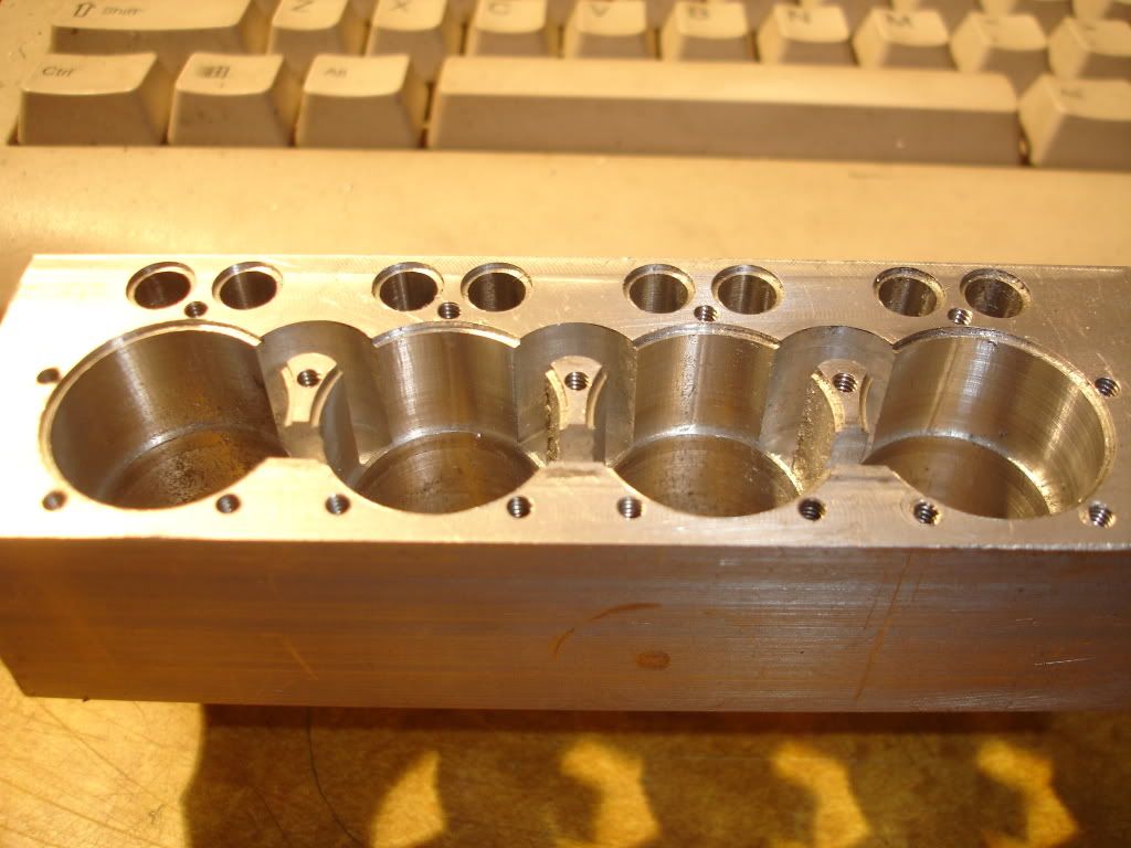
Today was the day to cut in water jackets. I counterbored the cylinders 5/8 deep then cut channels between them. The water is going to enter low in the front and exit high in the back through a channel not yet cut. I intend to drill a Channel parallel to but above the camshaft to just before the distributor shaft. From there I'll branch to the left and right rear cylinder water jacket. Wish me luck. This block is getting so many holes in it it'll most likely collapse in the vise. I had dreamed of returning the water through a channel in each head but there's just no room in the heads for a channel. Damn, a design oversite i guess.
DSC02284.jpg

DSC02288.jpg
 
jpeter said:
Hey Trumpy, thanks for the code. If I was gonna do it again though I think I'd use g91 more. By using g91 I could cut all 8 teeth by just copying the code and pasting it 8 times. My wish though is to learn how to add a for-next loop or to increment a variable to run the loop 8 times and then end the program. There's got to be a way.

GDay All,

jpeter, I don't know about for-next loops, but I do know you can add a subroutine and then call it during the execution of the code. Unfortunately, I'm still not sure how it actually works and from the code that I've seen, it differs greatly from one controller to the next. For that reason I tend to code without it, that way I can use the code on just about any controller, should the need arise.

Looking at your latest pics, I'm guessing that this is going to be a flat head, side valve engine?

It looks great whatever it is :big: And I'm totally jealous because you're actually doing it and I'm still dreaming :big:
 
jpeter said:
My wish though is to learn how to add a for-next loop or to increment a variable to run the loop 8 times and then end the program. There's got to be a way.


Check into the M98 command


"M98 P100"

This line will jump to sub routine 100


This would be sub 100

"O100
command
command
command
M99"

The first line is the letter O and the number 100
 

Latest posts

Back
Top