Towards the end of Captain Jerry's most entertaining thread on his Encabulator build, Mike Flannery accidentally called it an Ecabulatometer - Jerry replied that he knew of no such thing and I suggested I would invent & build one.
I built it - it didn't work due to a damn fool error in the design - so, disenchanted with it, I worked on my V4 wobbler - once that was out of the way, I went back to the Encabulometer.
Since I don't want to steal any of Jerry's thunder I decided to rename it the Improbability Drive. Alternatively its an Inside Out Radial.
Why ? it's improbable because the pistons go up and down twice for each revolution of the "crankshaft"
It uses the Archimedian principal of "give me a place where I can rest my lever...." and the "Square Peg In A Round Hole" valve system.
I want to see which member of HMEM is the first to figure out what makes it tick.
The 8 radial cylinders work outwards via levers.
It has no practical application - but then who said this hobby has to make sense.
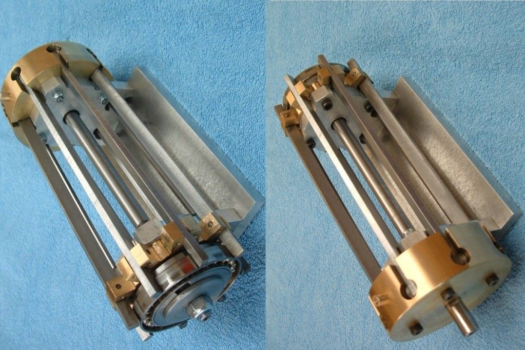
Here's a picture of the finished engine..

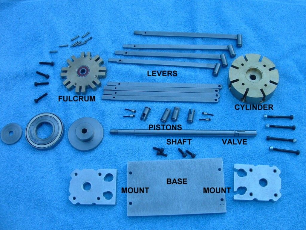
And all the bits....

And detail of the valve "Square Peg" - air entrers the groove to be distributed to the inlet ports in the base of each cylinder - twice per revolution - and the exhaust similarly out the side of the shaft.

Here's a video of it running - please note during the slow part of the run you can see the tacho marking tape goes around once while the pistons go up and down twice ? - curiouser and curiouser said Alice.
You might also note that opposing pistons go up at the same time.
[ame=http://www.youtube.com/watch?v=-uXzTesmZCI]http://www.youtube.com/watch?v=-uXzTesmZCI[/ame]
It starts off at ±50 rpm - so you can see the pistons cycling at twice the output shaft speed - I then goose it up to 950 rpm - at that point it starts to get noisy - but who's interested in speed anyway.
It works without a flywheel - but I added one to get the really slow motion (its actually a turntable off a 1948 Wurlitzer 1100 Jukebox temporarilly pressed into service).
Why did I build this ? .......... why not ! - it amuses me.
Ken
I built it - it didn't work due to a damn fool error in the design - so, disenchanted with it, I worked on my V4 wobbler - once that was out of the way, I went back to the Encabulometer.
Since I don't want to steal any of Jerry's thunder I decided to rename it the Improbability Drive. Alternatively its an Inside Out Radial.
Why ? it's improbable because the pistons go up and down twice for each revolution of the "crankshaft"
It uses the Archimedian principal of "give me a place where I can rest my lever...." and the "Square Peg In A Round Hole" valve system.
I want to see which member of HMEM is the first to figure out what makes it tick.
The 8 radial cylinders work outwards via levers.
It has no practical application - but then who said this hobby has to make sense.
Here's a picture of the finished engine..

And all the bits....

And detail of the valve "Square Peg" - air entrers the groove to be distributed to the inlet ports in the base of each cylinder - twice per revolution - and the exhaust similarly out the side of the shaft.

Here's a video of it running - please note during the slow part of the run you can see the tacho marking tape goes around once while the pistons go up and down twice ? - curiouser and curiouser said Alice.
You might also note that opposing pistons go up at the same time.
[ame=http://www.youtube.com/watch?v=-uXzTesmZCI]http://www.youtube.com/watch?v=-uXzTesmZCI[/ame]
It starts off at ±50 rpm - so you can see the pistons cycling at twice the output shaft speed - I then goose it up to 950 rpm - at that point it starts to get noisy - but who's interested in speed anyway.
It works without a flywheel - but I added one to get the really slow motion (its actually a turntable off a 1948 Wurlitzer 1100 Jukebox temporarilly pressed into service).
Why did I build this ? .......... why not ! - it amuses me.
Ken


