When I first started making hit-miss engines, about 15 years ago, I got
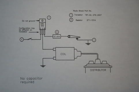
this schematic from another model engineer. I do not know who drew it originally but it looks a lot like the one on page 168 of Ignition Coils and Magnetos In Miniature by Bob Shores. He states he got it from Bruce Satra. The main difference I can see is that the Shores diagram includes a 10k ohm resistor between the coil and the spark plug where the circuit I use does not. (I cant show the Shores circuit due to copyright.) I do wonder if the resistor would cause a hotter spark??
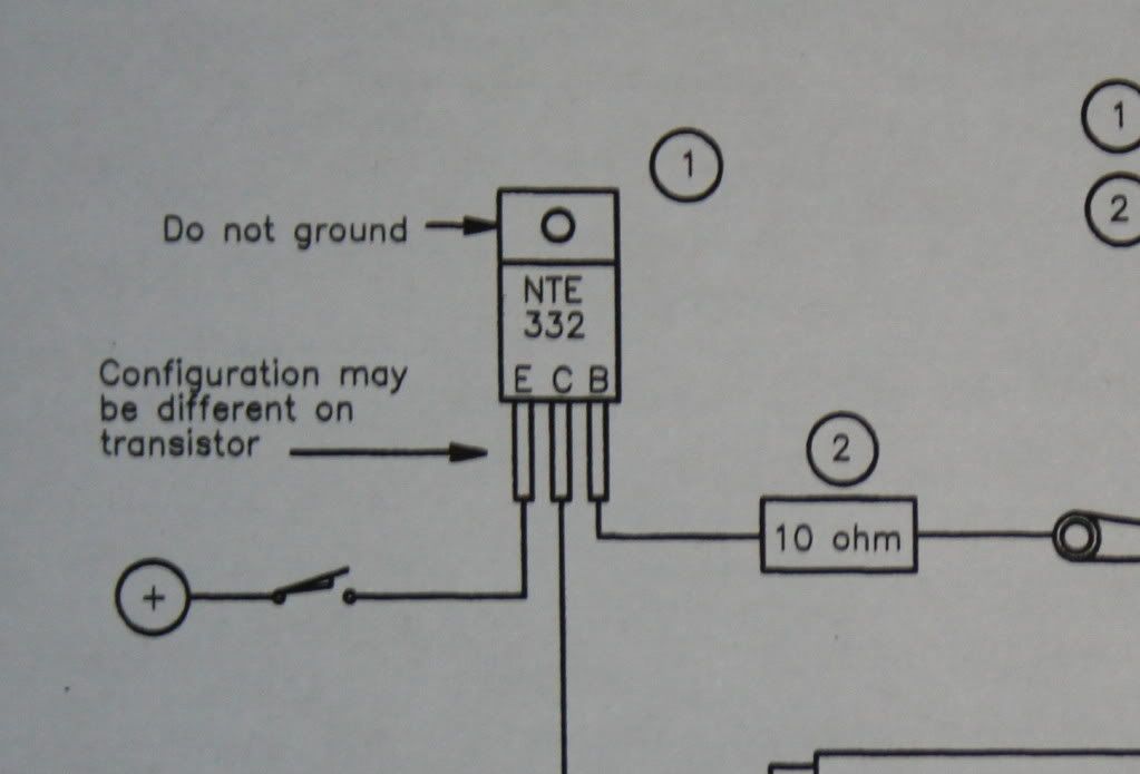
The second picture is a close-up of the transistor connections. As I understand it DC current from the battery feeds to the transistor and is connected to the Emitter. Current passes from the Emitter to the Collector depending on the bias voltage of the Base. The connections are marked E C B on the transistor. As noted on the diagram different transistors use different arrangements for the connections. It could be B E C or C E B or whatever. Be sure to connect them properly.
Think of the Base as the handle on a faucet, turn it on current flows, turn it off it stops. The Base is turned on and off by connecting it to ground through the 10 ohm resistor. There is only a very small amount of voltage and current passing from Base to ground so no arcing occurs.
That is why you do not need special points. Any piece of wire will work. So where the diagram shows a set of points, substitute any kind of simple contact. I personally prefer small paper clips although I once used a piece of 22 g electrical wire. Any metal contact should work.
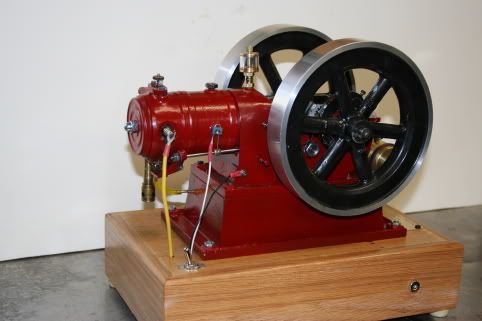
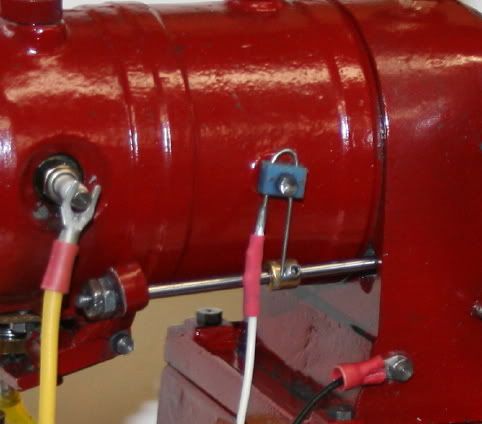
Above is my latest hit-miss engine. In the first picture the yellow wire is the lead to the plug. The white wire is the Base to ground wire and the black wire is ground to the body of the engine. The second is a close-up where you can clearly see the connection to the paper clip contact. The blue thing is just a piece of plastic to hold the paper clip and keep it from grounding constantly. The paper clip extends down to a brass contact on the rod that operates the valve. The rod is electrically grounded to the engine body and then the ground wire.
At top dead center the rod jumps forward and touches the Base ground contact, which turns on the current flow thru the transistor. It instantly moves back, breaks the base ground connection which turns off the transistor and of course causes the magnetic field in the coil primary to collapse and pop goes the spark plug.
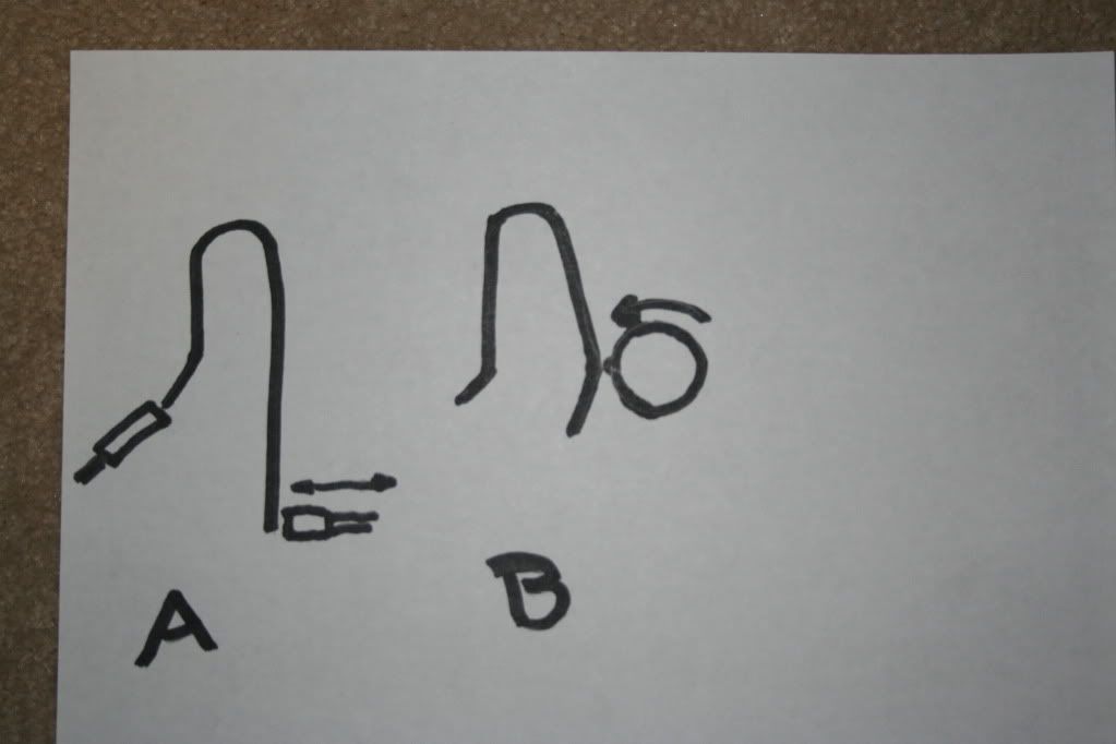
Below is a drawing showing a couple of methods I have used to operate contacts. A is the one I described above and is specific to the engine. B is one where a shaft rotates a cam to make contact. In my application the cam is simply a round head screw on a small disk. There is probably a thousand ways to operate contacts.
A couple of comments on parts. The transistor specified is a NTE 332 which I used several times. When the store ran out they sold me a different but electrically equal substitute. Worked just fine. That made me think, why not other similar transistors. I happened to have purchased a junk bag of various transistors(about 400) for two dollars and started testing them in my circuit. Found that most power transistors work. I now have almost 50 transistors ready for use.
Power transistors are the bigger, sort of square ones versus the small round cans or round plastic with a flat area. Power transistors are everywhere. Tear apart almost any electrical device and you will find them. Go for the ones that are connected with long leads and just cut them off. De-soldering is a pain.
Be sure to mount the transistor on a heat sink. They can get very hot and even cause a fire. I once charred a piece of oak when I let the engine stop at top dead center too long. More than a few seconds can destroy the transistor. A piece of 1/8" thick aluminum 1"x2" will do. Oh yeah, don't grab hold of it until it cools off. Don't ask me how I know.
I have only used this on single cylinder, low speed engines so I do not know if it will work on fast multi-cylinder engines.
Be aware there are two different types of transistors, PNP and NPN. I can't explain the differences but I think the NTE 332 is a PNP type. Just be sure you use the same type as a NTE 332 if you go for salvage transistors.
Use slide on connectors to attach the wires to the transistor rather than solder. It is easy to ruin a transistor by allowing the engine to stop at a point where the contact is closed causing a constant current flow. Only takes a short time to overheat and burn out. With slide-on connectors replacement is a snap.
Lastly, I hope some of you with a better understanding of transistors and electronics will jump in and correct any errors or misconceptions I may have made.
this schematic from another model engineer. I do not know who drew it originally but it looks a lot like the one on page 168 of Ignition Coils and Magnetos In Miniature by Bob Shores. He states he got it from Bruce Satra. The main difference I can see is that the Shores diagram includes a 10k ohm resistor between the coil and the spark plug where the circuit I use does not. (I cant show the Shores circuit due to copyright.) I do wonder if the resistor would cause a hotter spark??


The second picture is a close-up of the transistor connections. As I understand it DC current from the battery feeds to the transistor and is connected to the Emitter. Current passes from the Emitter to the Collector depending on the bias voltage of the Base. The connections are marked E C B on the transistor. As noted on the diagram different transistors use different arrangements for the connections. It could be B E C or C E B or whatever. Be sure to connect them properly.
Think of the Base as the handle on a faucet, turn it on current flows, turn it off it stops. The Base is turned on and off by connecting it to ground through the 10 ohm resistor. There is only a very small amount of voltage and current passing from Base to ground so no arcing occurs.
That is why you do not need special points. Any piece of wire will work. So where the diagram shows a set of points, substitute any kind of simple contact. I personally prefer small paper clips although I once used a piece of 22 g electrical wire. Any metal contact should work.


Above is my latest hit-miss engine. In the first picture the yellow wire is the lead to the plug. The white wire is the Base to ground wire and the black wire is ground to the body of the engine. The second is a close-up where you can clearly see the connection to the paper clip contact. The blue thing is just a piece of plastic to hold the paper clip and keep it from grounding constantly. The paper clip extends down to a brass contact on the rod that operates the valve. The rod is electrically grounded to the engine body and then the ground wire.
At top dead center the rod jumps forward and touches the Base ground contact, which turns on the current flow thru the transistor. It instantly moves back, breaks the base ground connection which turns off the transistor and of course causes the magnetic field in the coil primary to collapse and pop goes the spark plug.
Below is a drawing showing a couple of methods I have used to operate contacts. A is the one I described above and is specific to the engine. B is one where a shaft rotates a cam to make contact. In my application the cam is simply a round head screw on a small disk. There is probably a thousand ways to operate contacts.

A couple of comments on parts. The transistor specified is a NTE 332 which I used several times. When the store ran out they sold me a different but electrically equal substitute. Worked just fine. That made me think, why not other similar transistors. I happened to have purchased a junk bag of various transistors(about 400) for two dollars and started testing them in my circuit. Found that most power transistors work. I now have almost 50 transistors ready for use.
Power transistors are the bigger, sort of square ones versus the small round cans or round plastic with a flat area. Power transistors are everywhere. Tear apart almost any electrical device and you will find them. Go for the ones that are connected with long leads and just cut them off. De-soldering is a pain.
Be sure to mount the transistor on a heat sink. They can get very hot and even cause a fire. I once charred a piece of oak when I let the engine stop at top dead center too long. More than a few seconds can destroy the transistor. A piece of 1/8" thick aluminum 1"x2" will do. Oh yeah, don't grab hold of it until it cools off. Don't ask me how I know.
I have only used this on single cylinder, low speed engines so I do not know if it will work on fast multi-cylinder engines.
Be aware there are two different types of transistors, PNP and NPN. I can't explain the differences but I think the NTE 332 is a PNP type. Just be sure you use the same type as a NTE 332 if you go for salvage transistors.
Use slide on connectors to attach the wires to the transistor rather than solder. It is easy to ruin a transistor by allowing the engine to stop at a point where the contact is closed causing a constant current flow. Only takes a short time to overheat and burn out. With slide-on connectors replacement is a snap.
Lastly, I hope some of you with a better understanding of transistors and electronics will jump in and correct any errors or misconceptions I may have made.


