How would i machine this?

Home Model Engine Machinist Forum

Help Support Home Model Engine Machinist Forum:

This site may earn a commission from merchant affiliate links, including eBay, Amazon, and others.
Joined
Jan 19, 2008
Messages
86
Reaction score
4
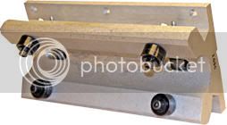
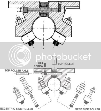
This isn't really related to model engineering but i could do with some help with how to make something that closely resembles this:
jet_ra4.jpg

jetrail.jpg


Its a linear slide for a rapid prototyping printer that im thinking of making so tolerances need to be very tight. I need two for each axis, around 140mm long to suit a 12mm shaft.
I cant for the life of me work out how to mill the angles (mounting is proving to be a problem) so any advice would be appreciated

Regards
Jonathan
 
You either need an adjustable angle plate or at least a tilting vise, so you can set your angles. If the angles must be dead nuts then a vernier protractor or a sine bar would be needed to set the tilt.

The tilting angle plate and sine bar can be made in the shop without too many hassles. They will be with you for the rest of your machining and are a worthwhile addition to your shop.

Hope this helps.

Best Regards
Bob

 
Mount a longer piece of metal in a vertical rotary table with the other end supported by a centre and rotate to get the required angles.

If you have a DRO with ARC function then you should also be able to do most of te curved section as well.

J
 
Perhaps it's a possibility to do it like this:
angleblock.png

You can calculate or draw the distance needed for your angle.

Good luck
 
Thanks for the ideas. Its not so much the angles that have to be spot on but more the hole locations along its axis. Problem is that i dont have most of the tools to make life easy (rotary table, tilting vice, DRO etc) but i guess it gives me a reason to spend more of the money i dont have ::)
 
It's surprising what you can do with an ordinary vice and a few taper wedges if you put your mind to it.
 
Additionally, if you have a ram type mill with head tip, you could go that way.


Just keep it simple. I don't think any of those angles are that critical.

Dave
 
The angles are all achievable with a 30-60-90 angle bar.

Looking at the drawing, it seems to me that the part itself doesn't need to be particularly precise other than a few parts. Example: the semi-circular channel can be square as it doesn't touch the bar.

If you machine the top surface flat, then the slides can be adjusted pretty precisely by fitting the roller diameters.
 
The same way I set up to cut a 90 degree "V" cut for the eccentric slide for my PM Research 5BI.

I lightly clamped it in my vice so it could be turned and set the angle with a square. A sine bar would do the same job with accurate results. The picture below shows me aligning the frame at a 45 degree angle with a precision dowel pin.

DSC00367.JPG
 
If the angle isn't the problem but the accuracy of your holes you could use your 12 mm shaft,
Drill the hole, ream/turn it to the right dimension for your 12mm shaft position.
Now you can use your 12mm shaft for locating the hole's
The precision you get depends on you re shaft/hole

the only thing you need is a edgefinder to get a decent accuracy

Good luck
 
A 1/2" ball mill would give the radius and clearance for the shaft, then as mentioned use angle blocks to mill the flats and drill the holes for the rollers.
 

Don't just look for ways to machine it but look at ways to redesign so that you don't have to do as much machining.

As KVOM stated the center slot does not need to be radius it could be cut with a straight end mill. In doing this you would also make the part lighter.

Another example is the set screw for the top shaft. The grease fitting contains the shaft at one end and drilling and tapping the other end and putting in a set screw to contain the shaft without the need for setting up for and drilling a tapping a separate set screw hole.

For the side rollers redesign for the roller shafts to be threaded to the body with out the nut on the top. This eliminates the need to machine the area where the nuts are. If there is a weight problem you could still machine that area out but it does not need to be at an angle or that precise.
 
I would also machine the bottom two bearing bolts as an eccentric to take up any slack or future wear.
 
techonehundred said:
I would also machine the bottom two bearing bolts as an eccentric to take up any slack or future wear.
why would you do that when they are adjustable? they can be preloaded and then locked off with the locknuts (or am I missing the point) plus one side is already on an eccentric bush for initial set up, i think they are past the centre of the shaft, so when "nipped up" they tighten onto the shaf slightly
 
Although it would take all the fun out of making your own, I would look on ebay for Thompson linear bearings and rail. A lot less work and likely cheaper than making your own.
 
why would you do that when they are adjustable? they can be preloaded and then locked off with the locknuts (or am I missing the point) plus one side is already on an eccentric bush for initial set up, i think they are past the centre of the shaft, so when "nipped up" they tighten onto the shaf slightly

Ok, I guess I need to look a little closer before I reply. :Doh: I now see that you have two of the bolts already on an eccentric.
 
As Stan points out it may not be as much fun, but there are several "home brew" RP machine designs out there now, and to my knowledge, many if not most of them use off the shelf components for the x,y, and z axes. That also helps as things begin to wear...simpler replacement of worn components, etc. Assuming you are going for an FDM (fused deposition modeling) type machine, the extrusion head is going to be the trickiest part I would think.

Bill
 
Stan said:
Although it would take all the fun out of making your own, I would look on ebay for Thompson linear bearings and rail. A lot less work and likely cheaper than making your own.
I had originally thought of that and ended up getting some 12mm shafting and linear bearings from vxb, but as i had expected the linear bearing are far from smooth(Thompson would probably be much better). I made a mock up linear slide with ball bearings which was much smoother which sold me on this design. The design as shown above will defiantly be redesigned i just wanted to know the best way to machine the angles.
What way do you guys find best to index the sides of a work piece? I'm using an old imperial (I work in metric)starrett wiggler set atm which is a bit of a pain
 
I would suggest you reconsider the design of the bearings. The load of the Head/work is being carried by a Steel Roller running on a steel axle shaft, No bearings in that roller? Thurst bearings? washers even. As this part wears, and it will quickly, the nice BB quide wheels loose contact with the rail, and wander as they like, leading to not any chance of accuracy. The load rollers are the critical parts of the assembly, they need to be designed for the application.

Now I am assuming that the part is in the orintation as shown, load on top. As an example I know about, a Large Format inkjet printer, the print head weights 70 lbs, is carried by twin tompson "T" and 6 ball carriers.

With the information given, I may still be way off.
 
MachineTom said:
I would suggest you reconsider the design of the bearings. The load of the Head/work is being carried by a Steel Roller running on a steel axle shaft, No bearings in that roller? Thurst bearings? washers even. As this part wears, and it will quickly, the nice BB quide wheels loose contact with the rail, and wander as they like, leading to not any chance of accuracy. The load rollers are the critical parts of the assembly, they need to be designed for the application.

Now I am assuming that the part is in the orintation as shown, load on top. As an example I know about, a Large Format inkjet printer, the print head weights 70 lbs, is carried by twin tompson "T" and 6 ball carriers.

With the information given, I may still be way off.

The pictures were just a guide to the type of thing im thinking of. I will use ball bearings for all of the rollers and will probably need to make one side adjustable as shown. I see what you mean with the loading and it would be better if was oriented in a Y position with the two bearing on the top but i cant think of an easy way to do it, any ides?
Also a problem i have is where can i find thin washers to space the bearings off the bracket? i was thinking of using bearings with an extended inner ring but i cant find anything (ID around 5mm).
BTW this thing will be quite small, the build area will only be around 150mm and there wont be much weight put on the linear setup
 

Latest posts

Back
Top