How do I recess Flywheel Face

Home Model Engine Machinist Forum

Help Support Home Model Engine Machinist Forum:

This site may earn a commission from merchant affiliate links, including eBay, Amazon, and others.

Brian Rupnow

Design Engineer
Project of the Month Winner
Joined
May 23, 2008
Messages
15,250
Reaction score
8,532
Location
Barrie, Ontario, Canada
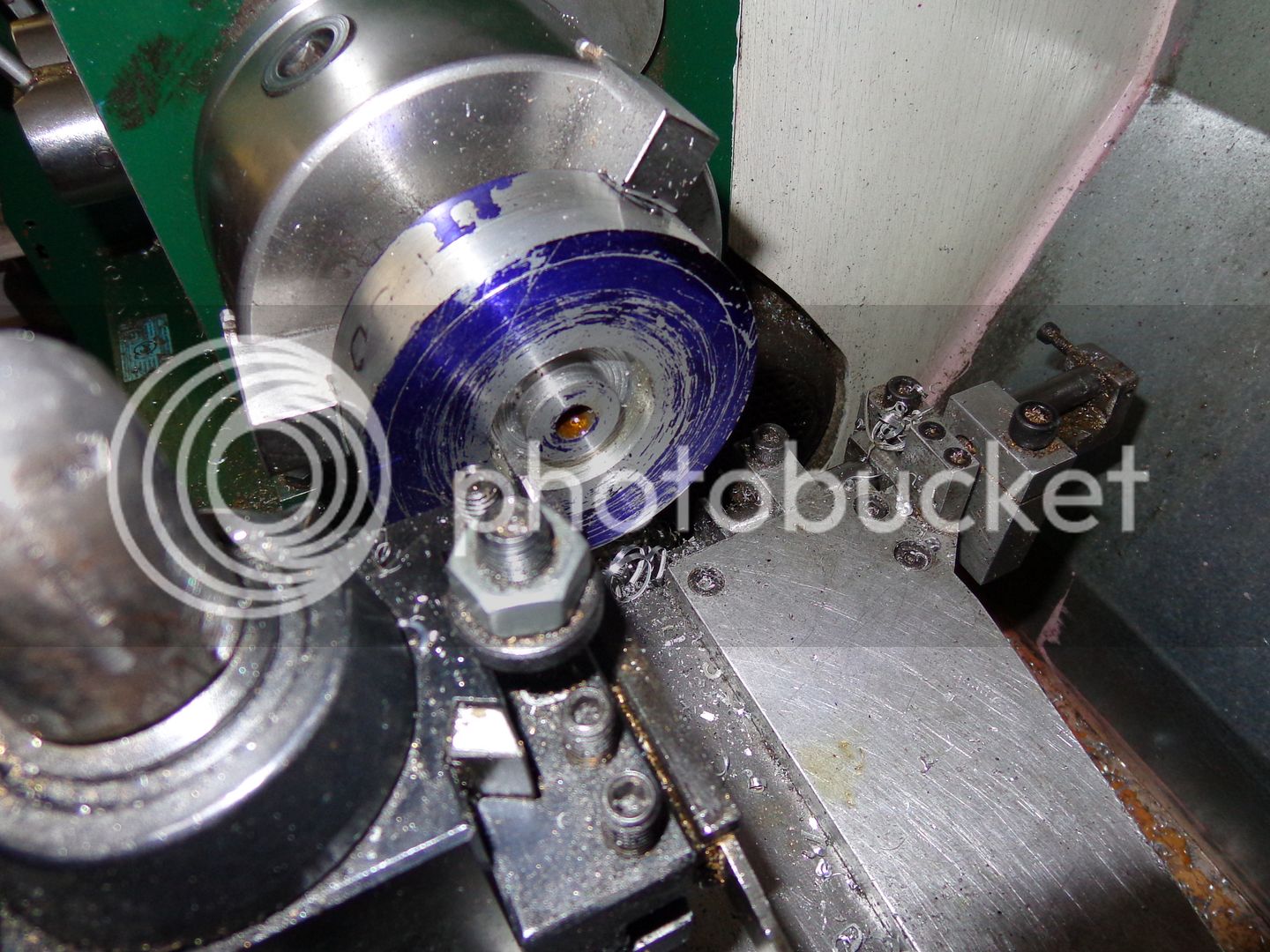
I need a quick tutorial on how to machine the recess into the face of my Odds and Ends flywheels. I have, up untill now, muddled my way thru countless flywheels using a parting off tool ground to a wicked taper and making a series of plunge cuts into the face of the rotating flywheel. (The parting off tool held at 90 degrees to how you would normally see it mounted.) This works---sort of. Its crude, its scary as Hell, and it leaves a dreadfull finish which must be sanded out to be even close to smooth. I could, I suppose mount the flywheel on my rotary table in the mill and using an endmill crank the rotary table around and around----But that hardly seems reasonable either. How do I, with the machinery I have, cut the recess in a better manner in my lathe? I am not set up to cut on the back side of my lathe or to mount tools upside down. The flywheel is aluminum. The recess is going to be 5/16" deep on both sides. Don't be alarmed that the outer rim looks thin--there is a section of heavy wall steel pipe getting Loctited to the o.d.---Any help would be appreciated.----Brian
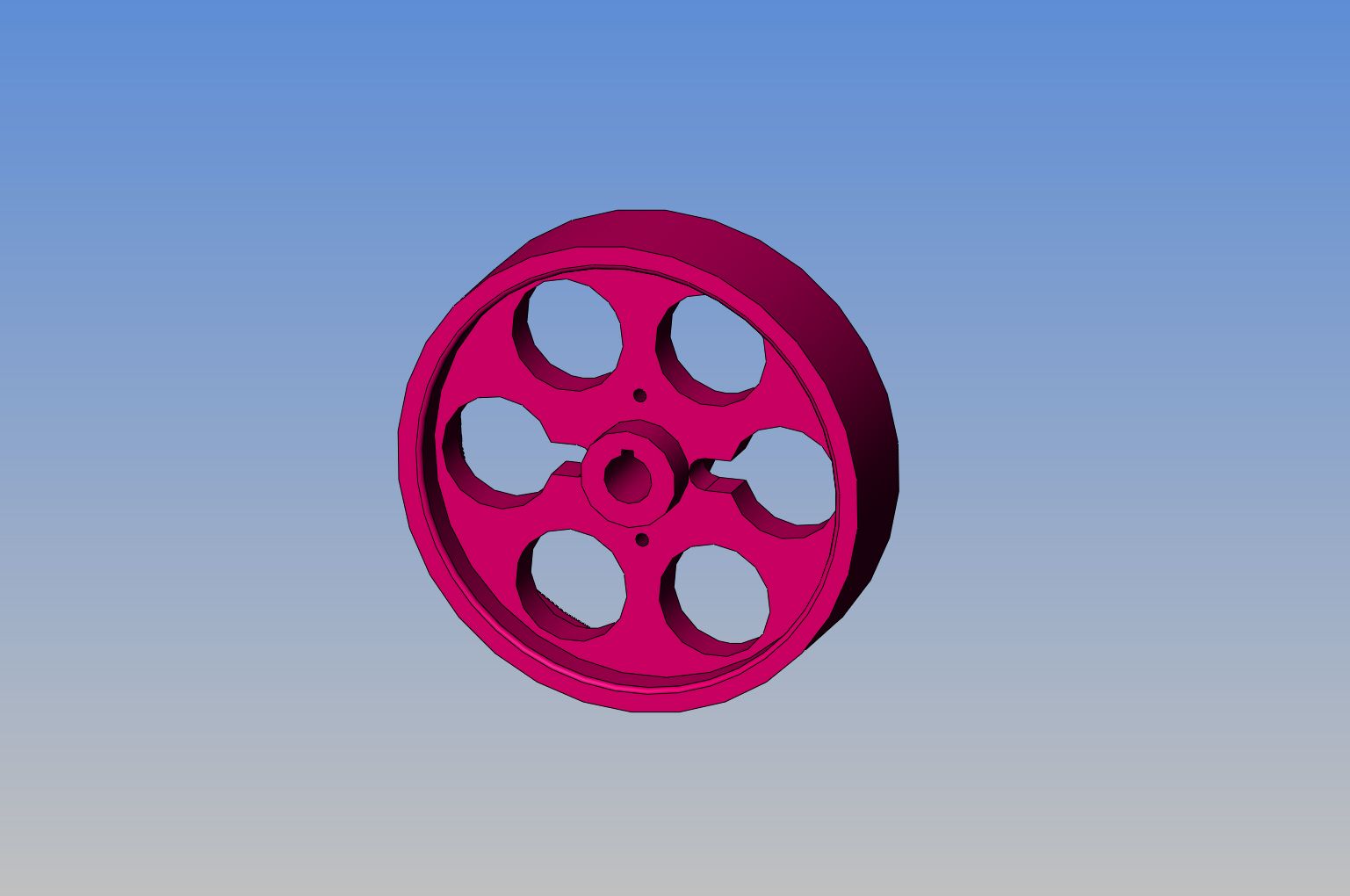
FLYWHEEL-2ODDSNENDS_zps1d5ef57f.jpg
 
Brian,

I use a boring bar to create the outer features and a standard pointy left hand turning tool (its got a better name than that but don't know it right now) to do the stuff around the hub.

I'll be interested to see if somebody has some better tricks...

Mike
 
Hi Brian,
I usually use left hand and right hand ground tools, mounted sideways in the toolpost.
The left hand tool especially has to have enough side relief to not hit the rim with the bottom of the tool. Starting from the inside, I gradually plunge a cut in then machine towards the outside, this is repeated, starting a bit further away from the centre each time until depth is reached. Then I use the other tool to finish off turning toward the centre.
( by left hand tool, I mean the way a tool bit is normally used for machining towards the left, maybe I have it the other way around)

Paul.
 
With a facing tool you can make a series of cuts consisting of a shallow axial plunge cut at about half radius or more, followed by a facing cut. Use these to rough out the hub close to diameter and depth. Each plunge will probably need to be at a slightly smaller diameter. You can then use a stubby boring tool to work outwards towards the rim. For finishing, the tools should have a generous radius. By setting each tool to the hub face and then working on the top-slide dial, the inward and outward cuts should coincide. Alternatively, if you want a single tool to do the whole job, make a tool like a D-bit, but remember that it will need the end ground dead square as part of the face will be formed rather than generated.
 
Hi Brian, Your special crankshaft cutting tools could easily be modified to cut this recess, Just watch your clearances. Regards Gary
 
Alright---I've looked at all the answers, both here and on the other forum I visit. I have a bunch of those cheap brazed carbide boring bars, and the smallest size is 0.290" wide at the tip. My evil looking parting tool that I have always used for this operation is .094" wide. Starting closest to the hub, I made 4 full depth plunges to the desired depth. Not all at one go---I plunged about .020", then moved out the width of the parting tool and repeated, jumping back and forth so that I wouldn't get the tool to deep into a single groove and have it bind and/or break. Now I can get the boring tool all the way down the slot to the desired depth. I have built adjustable carriage stops in both X abd Y directions on my lathe, so I should now be able to use the boring tool held in the toolpost and make succesive passes from the slot near the hub towards the outer rim, coming towards me, until the entire recess is done. I will post a pic tomorrow.---Brian.
 
Take a look at this article

http://www.cnccookbook.com/CCToolGrinding.htm

The tool you need is referred to as a trepanning tool, or a face grooving tool. You can cut the entire recess with this tool, or you can trepan one narrow slot to the depth you need, and use a boring bar to widen the groove toward the circumference, and a left hand counting tool to widen the groove toward the center of the flywheel. There is a link in the above article back to a HMEM post describing the tool better, but the photo links are broken in the HMEM article.
 
With a short and stout boring tool, for the rim side, then moving the same tool on the oposite side of the hub, you cut the hub side with the lathe running backward. Of course, a carriage stop is mandatory to get same depth, for an invisible joint. With a rounded tool, no need for a finishing touch up usually, but for very narrow recess.
Cheers
 
Good link, but the tool is very shallow. If you check the tools on the link below, and grind something along that line in depth, it makes a huge difference.

http://www.iscar.co.uk/Products.aspx/CountryId/16/ProductId/11

The other option if you want to finish the face with a single tool is to grind clearance in the centre as you can for a crankpin turning tool, so in effect you're cutting on a point either side, rather than full tool width, to reduce chatter.

There's a link with the tool style here:- http://www.oocities.org/mdbouch/model_engineering/machining_crank.html
 
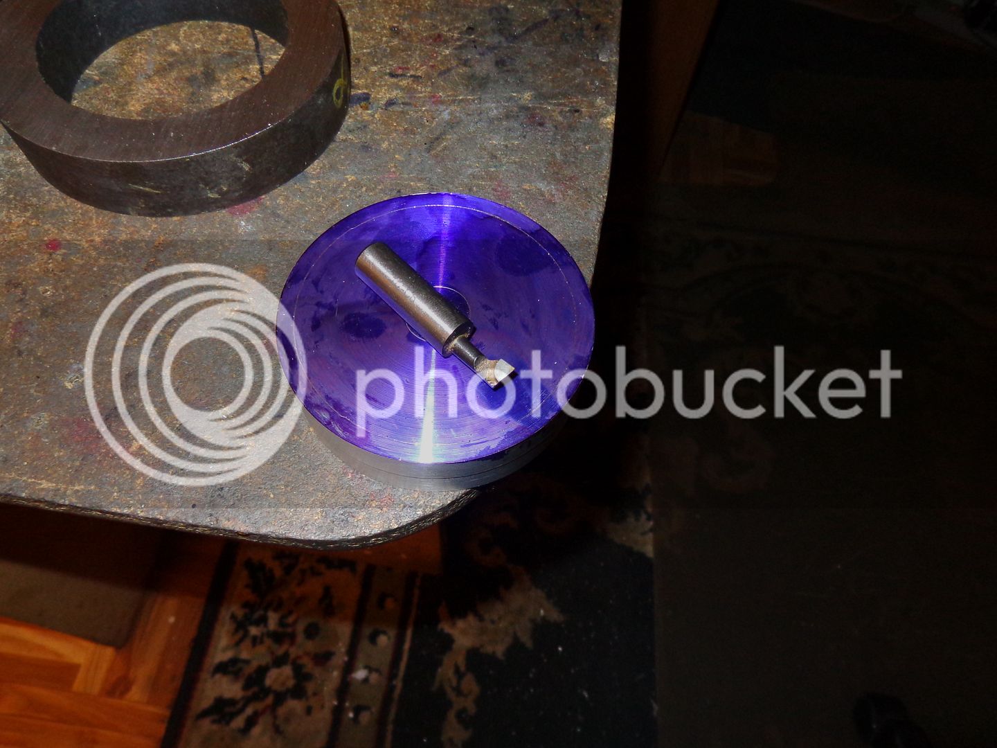
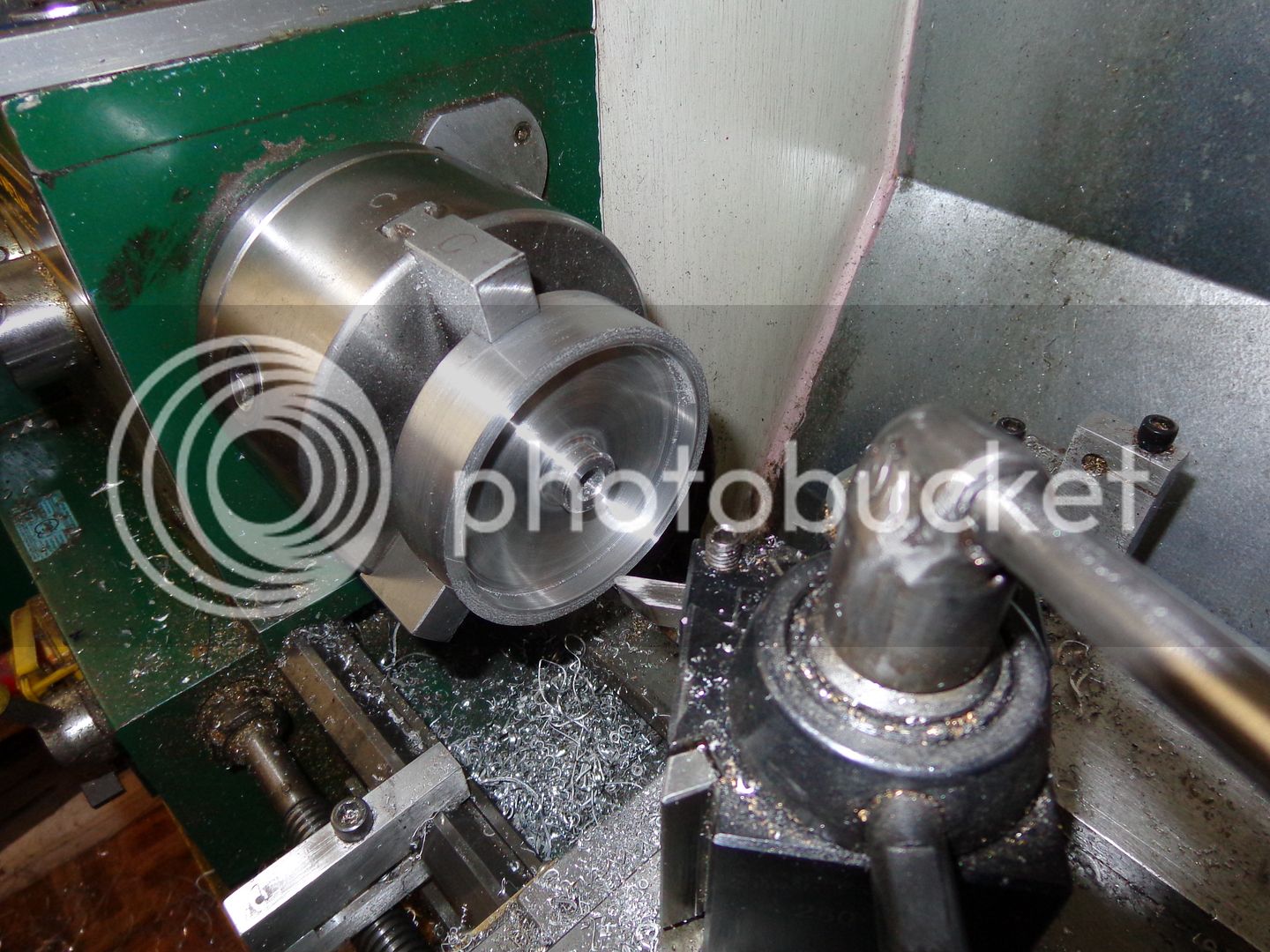
This is a picture of the flywheel blank with about .30 wide x 5/16" deep ring plunge cut at the side nearest the hub, and a picture of the boring tool which is going to be mounted in my toolpost and used to take succesive cuts towards the outer rim (towards me).
FLYWHEELRECESS001_zps168ebf48.jpg

FLYWHEELRECESS003_zpse03dc13b.jpg
 
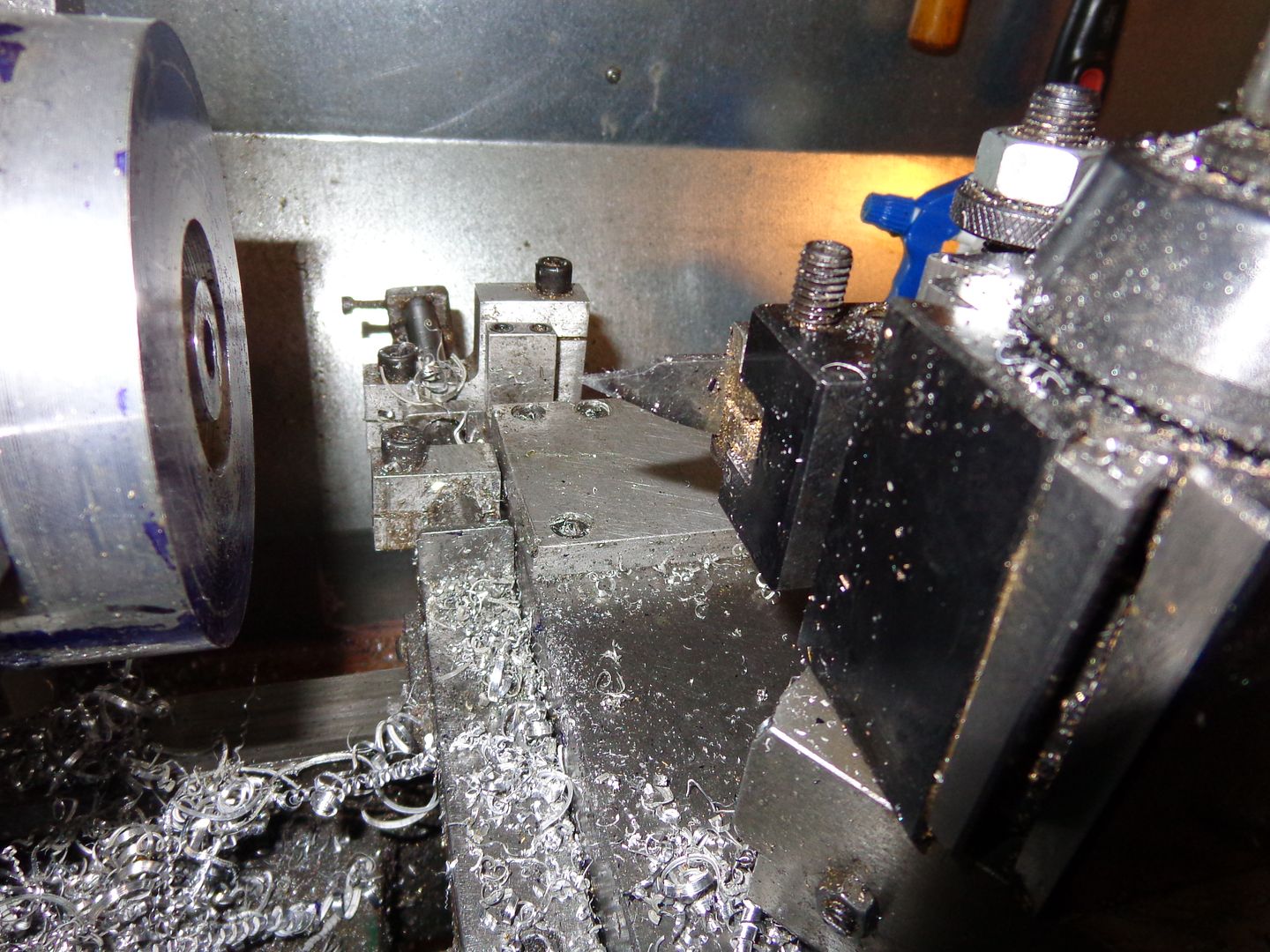
Well, that worked out almost perfect---and very smooth finish as well!!! The only remaining uglies are the bottom of the grooves made by the pointed parting off tool while making the initial plunge cuts. The boring tool works just great. Now I may grind a right and left radius nosed tool to do the final clean up with. I left the hub a bit oversized and the rim cut a bit undersized, so I would have a bit left for clean up after the major excavation.
FLYWHEEL-3001_zpsb97cdf1d.jpg
 
Since you now have the recess, a nice radius at the hub and the rim would be nice. A ball end mill works great at the this, a 1/4 EM has a `1/8 radius, mount the EM in a tool holder with one flute positioned as like you boring bar, set you depth stop, and plunge in, don't dwell as you may get chatter marks if you do. To do the hub side you will need to run the spindle in reverse and cut from the back side, most lathes have enough crosslide travel to get you there, if its a screw on chuck just be gentle its only a small cut, my SB 9 or 16 did not mind doing this, with no problem.
 
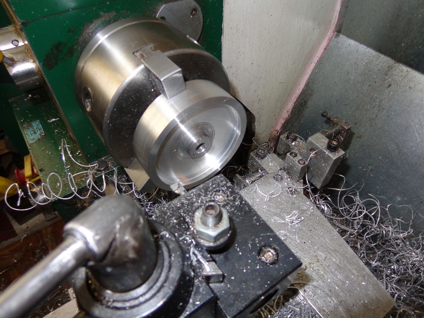
So there it is, a thing of beauty, and the tool I used for final finishing to size. I was able to flip the tool around in the tool holder and rotate the tool holder 180 degrees, thus allowing me to finish both the hub side and the inside rim all with the same tool. Thank you all so very much for your help and suggestions. Now if I can just do this 3 more times, the day will be a success!!!
FLYWHEELDONE001_zpsb1b04b56.jpg
 
Machine Tom--Thanks for the tip, but as I said earlier in this post, I am not set up to machine on the far side of the spindle, nor will I try cutting with tools mounted upside down or machining in reverse.
 

Latest posts

Back
Top