Horizontal Air Cooled Engine

Home Model Engine Machinist Forum

Help Support Home Model Engine Machinist Forum:

This site may earn a commission from merchant affiliate links, including eBay, Amazon, and others.
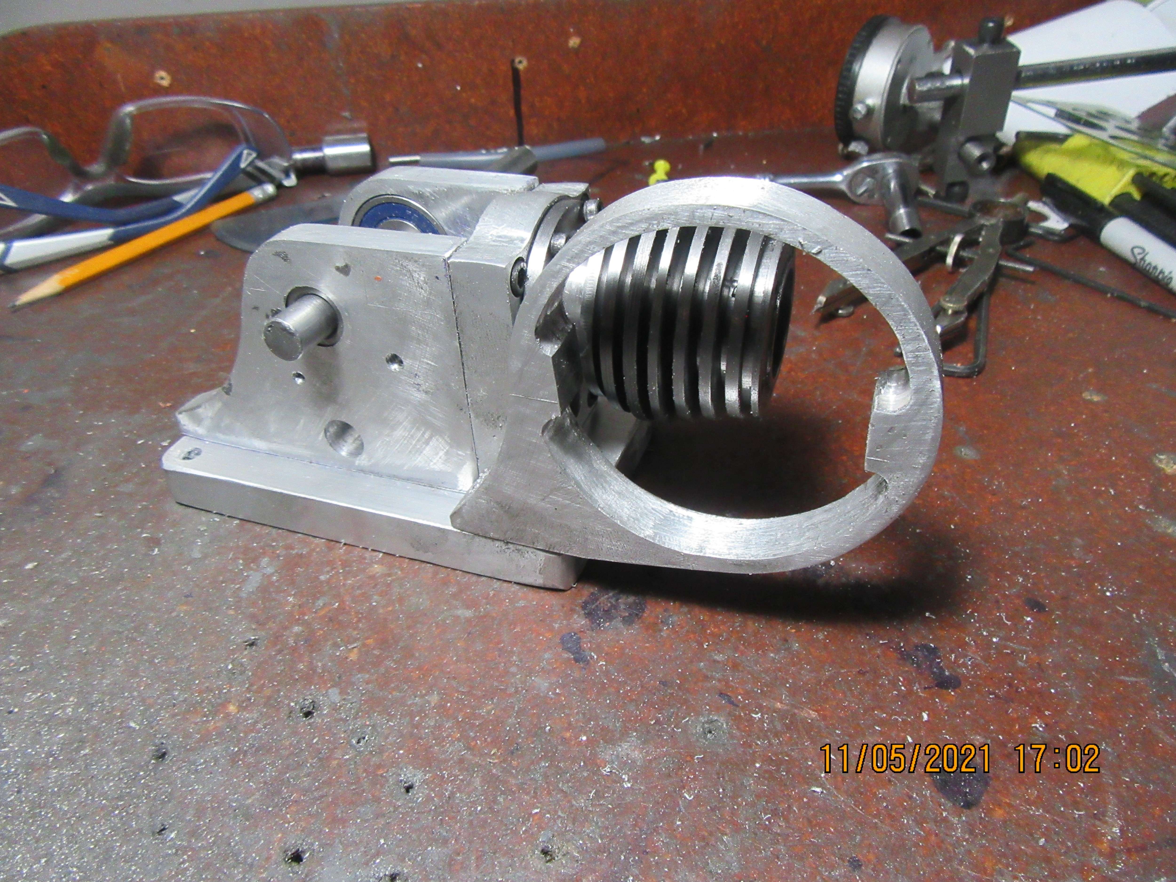
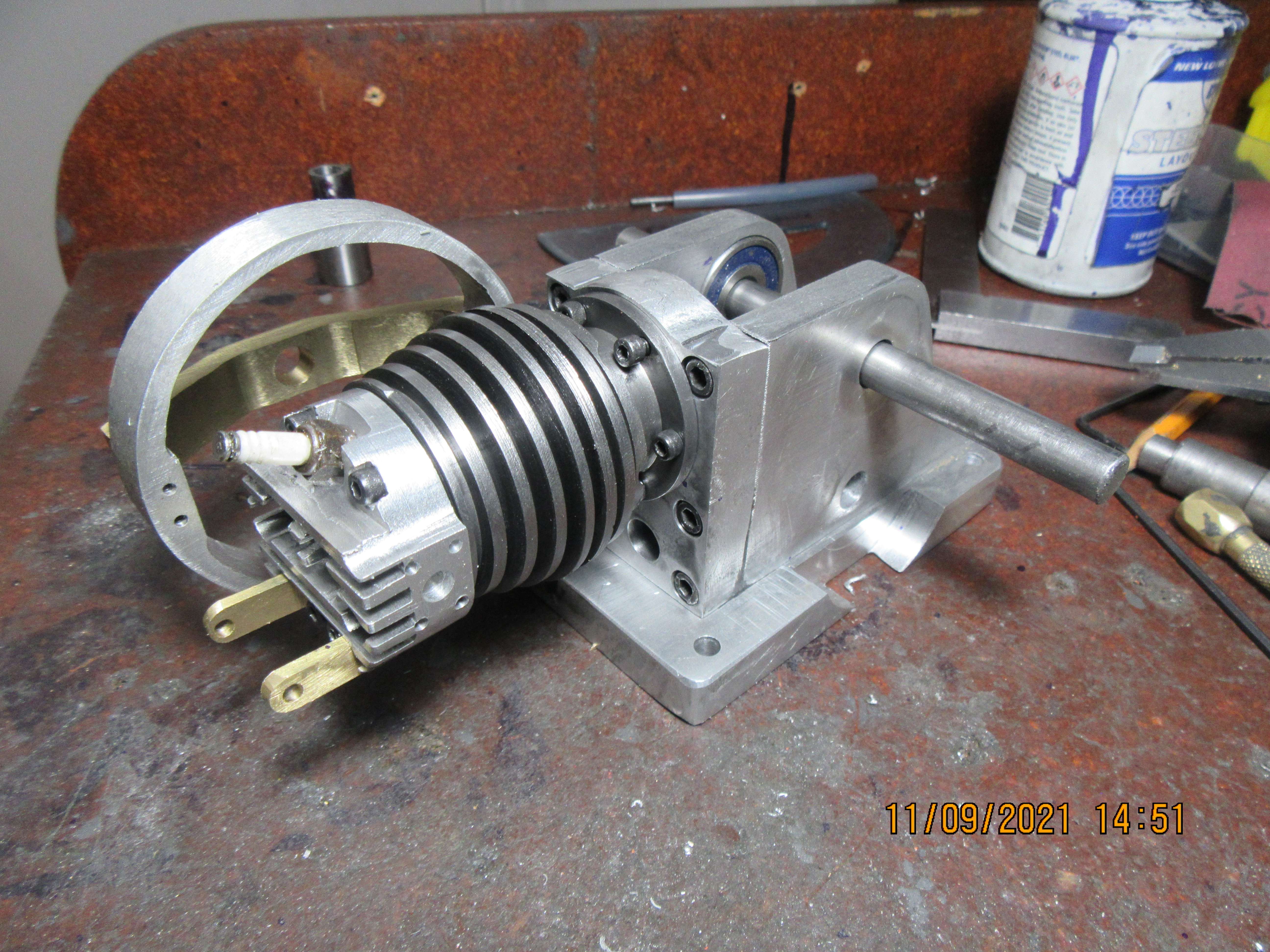
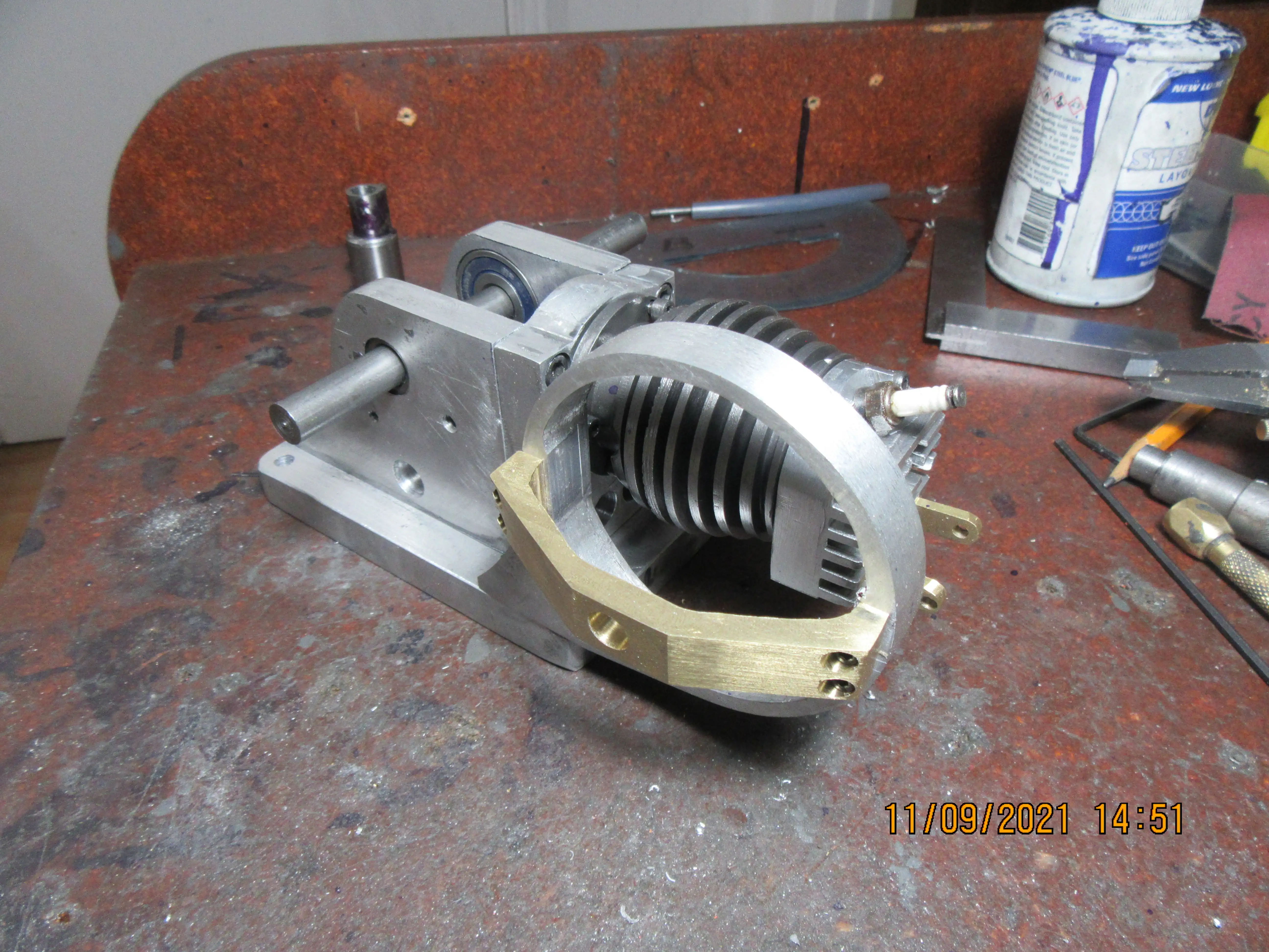
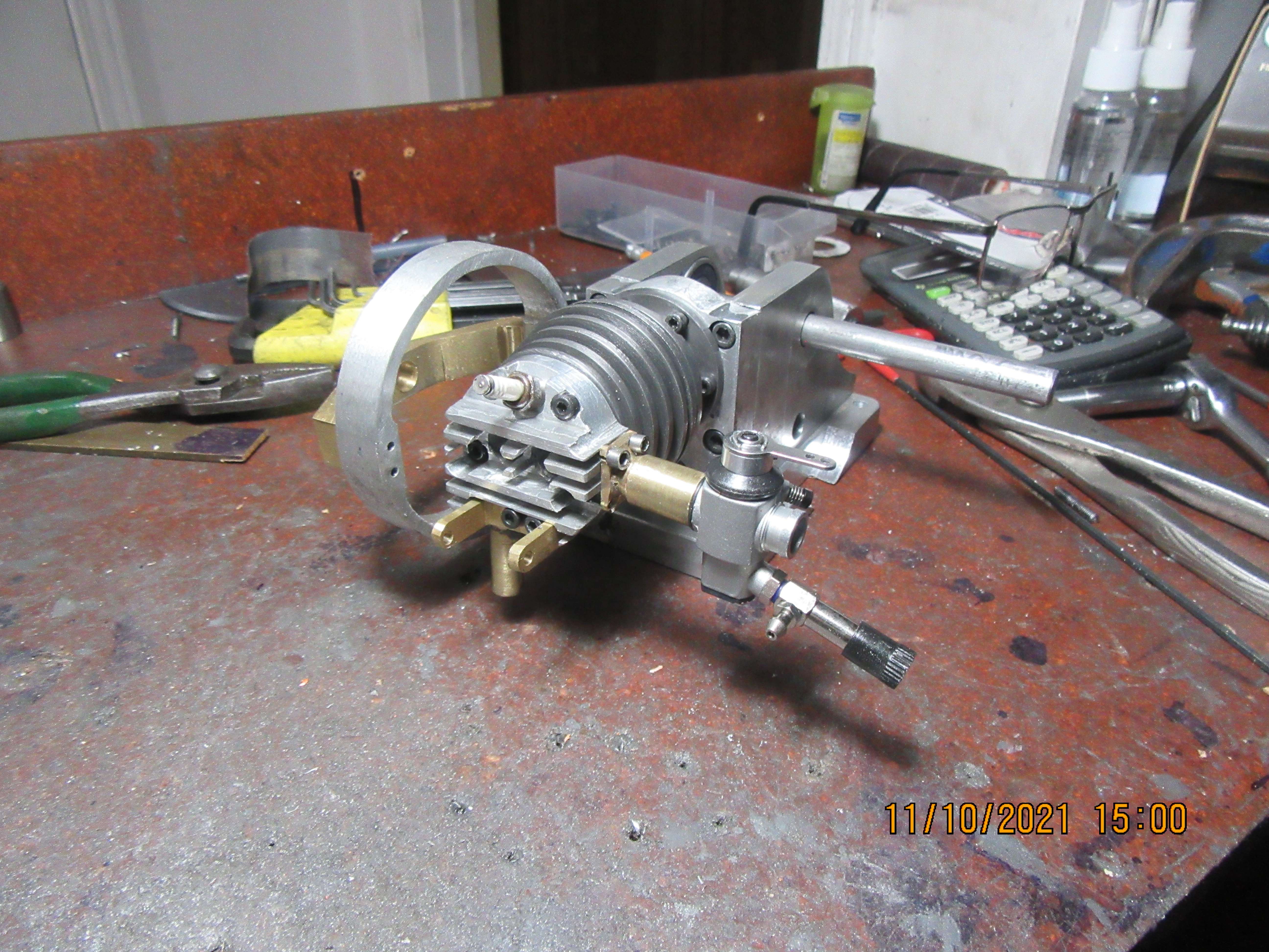
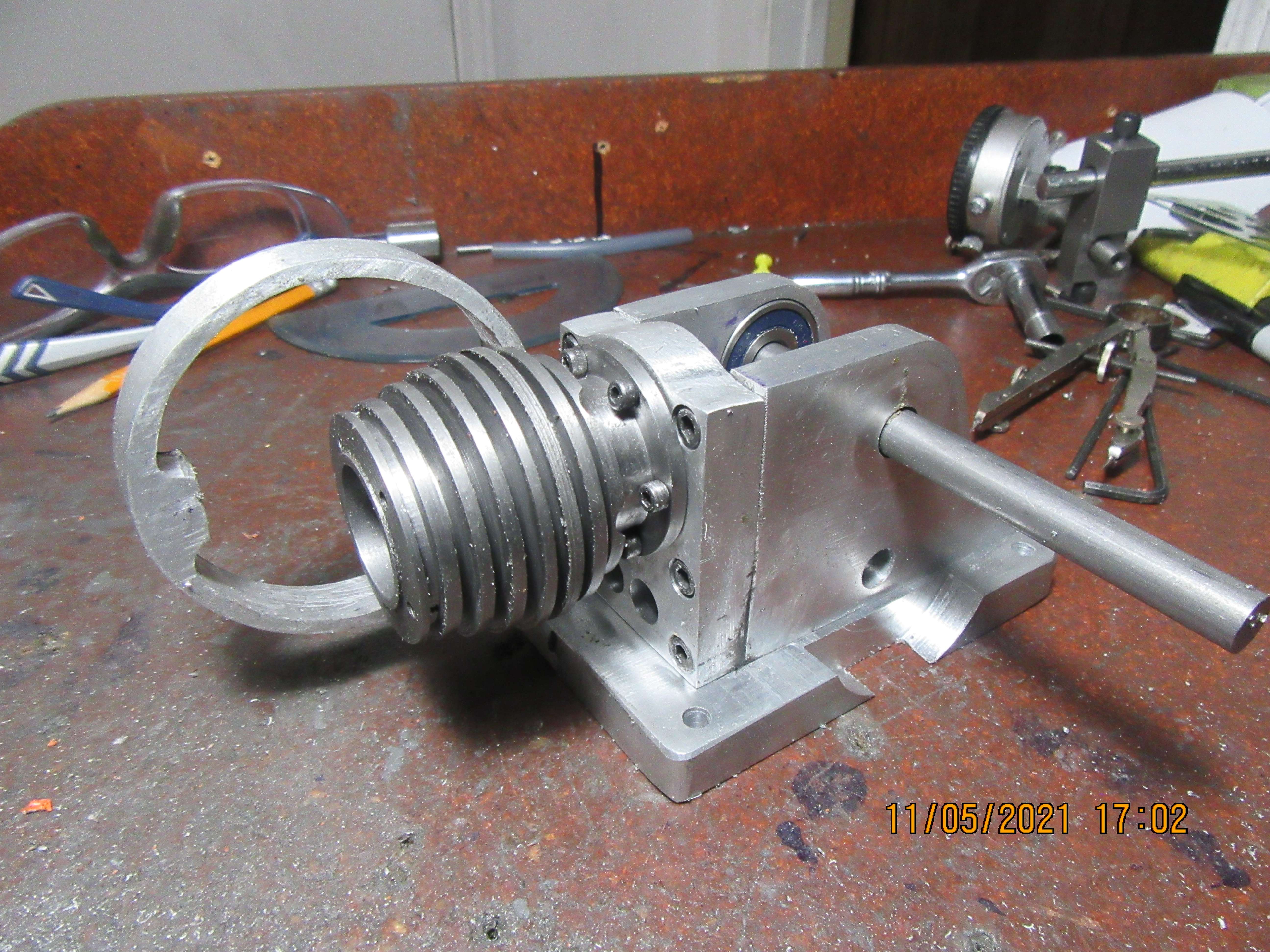
Today I drilled clearance holes in the cylinder base flange and drilled and tapped holes in the other end of the cylinder, and attached the cylinder to the frame. I really suffered getting the cylinder bolted to the chassis, and I'm going to change the design drawings of this to give a bit more wrench clearance. I also made the fan housing and installed it. I'm not really sure of how the finished fan and bearings are going to be attached, but for now I will just call it a work in progress.
CSZidU.jpg

QvX0GI.jpg
 
Hi Rob, yes I heard that about some Kawasakis, etc in the 1970s... I.E. A rich mixture "to avoid overheating". But from my and friends' experience, as long as the ignition timing is Not too far advanced, the mixture Stoichiometric, and the engine properly set-up, the rich mixture was just a myth for helping the engine.... soot developed in the wrong places that caused pre-ignition and consequential overheating failures. My last 2-stroke was a prod, racer LC350 with stage 3 tuning... needed 105 octane fuel, but correct mixture... I also knew a reliable Prod racer Kawasaki 500 triple in the 70s. Mixture critical, it had to be right, not rich. As did all the winning Yamahas when I used to Marshall at race meetings.
Myth proven by reality in my book....
K2
Yep. My mate raced go karts and was pretty successful in his class. I noticed all the racers putting their hands over the carby intake when braking into a corner.
I asked why and they explained that it sucks a lot of fuel into the engine and cools it rapidly. Most of the fuel went raw out the exhaust and they carried on with a tiny bit of "boost" coming out of the corner with the throttle wide open. Simply put down as a "race trick "
 
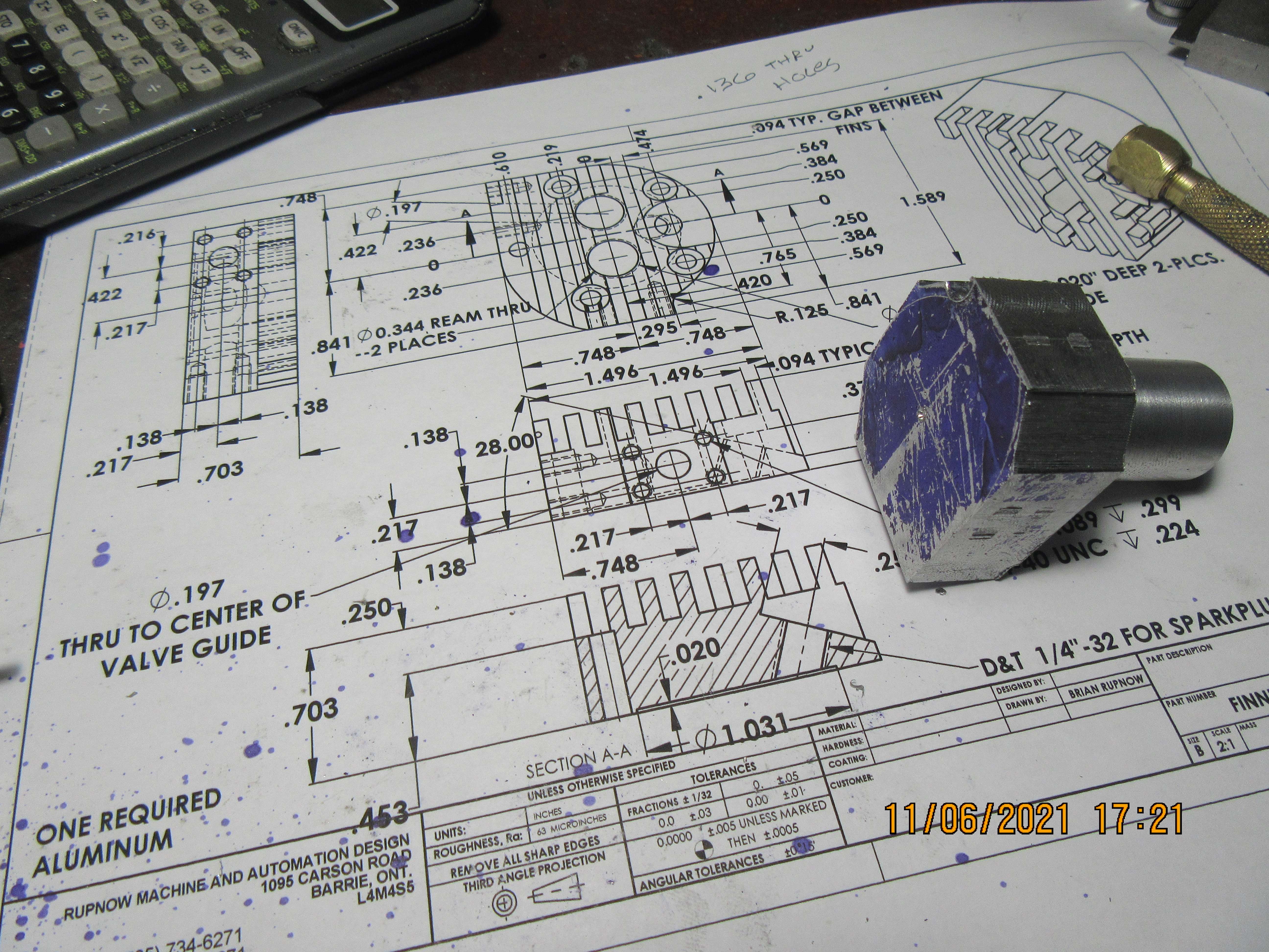
This cylinder head is a complex little guy to machine. None of the individual steps are difficult by themselves, but the hard part is having something to hold onto while you do them.---And if you don't do things in the correct sequence, you can easily "paint yourself into a corner". I do have a plan, and the first part of my plan is using my four jawed chuck in the lathe to turn a "stem" to hold onto with the chuck mounted on my rotary table for all of the following steps.
gQNYja.jpg
 
Yep. My mate raced go karts and was pretty successful in his class. I noticed all the racers putting their hands over the carby intake when braking into a corner.
I asked why and they explained that it sucks a lot of fuel into the engine and cools it rapidly. Most of the fuel went raw out the exhaust and they carried on with a tiny bit of "boost" coming out of the corner with the throttle wide open. Simply put down as a "race trick "
Hi Rob, maybe they were also aware that many seizures occur under severe braking on racing bikes fuel by petrol-oil mix for crank and bore lubrication. The carbs are set to shut off fuel completely, when the oil in the engine is pumped out (naturally) during engine braking, leading to seizures. The "choking" of carbs sucks some fuel-oil mix through due to the high vacuum, thus maintaining the oiling of parts that could otherwise seize.
Possibly on the carts the engines were higher tuned than bikes? (short races and easier to swap motors between races?). Also a wide ope carb choked so it cannot run will give more air charge - hence more braking from the engine, and will fire immediately the hand is removed and mixture is "leaned-out" back to stoichiometric? I guess this also turns-on the power faster than the milliseconds of opening and closing the throttle...? (Many carbs suffer on a highly tuned engine when the throttle is opened quickly and the vacuum drops rapidly between induction strokes. Fuel pumps were added even to production car carburretors to eliminate this issue!).
This process is of course completely different to a constant running condition of running a poorly cooled engine set rich at WOT (a truly "hot" engine) so that the rich mixture runs cooler than the stoichiometric mix and keeps the engine from over-heating - a real "petrol-cooled" engine. Just poor tuning! (A lack of "total engineering"!). I was aware that those guys never won races but often broke-down... Too much tuning, too little understanding... Deep wallets for the petrol pump attendants! I knew of a production racing Kawasaki 500 triple, tuned so highly it could get as low as 5 MPG! - We reckoned more than half the mixture was pumped out of the exhaust due to the highly tuned porting! It was sold (many times) as a road bike, as it didn't finish the longer races in its class! (races more than 17 miles long for the fuel it could carry!) The best on-road consumption was around 20 MPG. But it went like stink! I reached the speed limit (70MPH) in 3rd gear before 6000rpm... when the front wheel started to lift as it hit the power-band! - That was 1975...
Nostalgia ain't what it used to be...
Sorry Brian, I seem to have wandered from your engine making.
K2
 
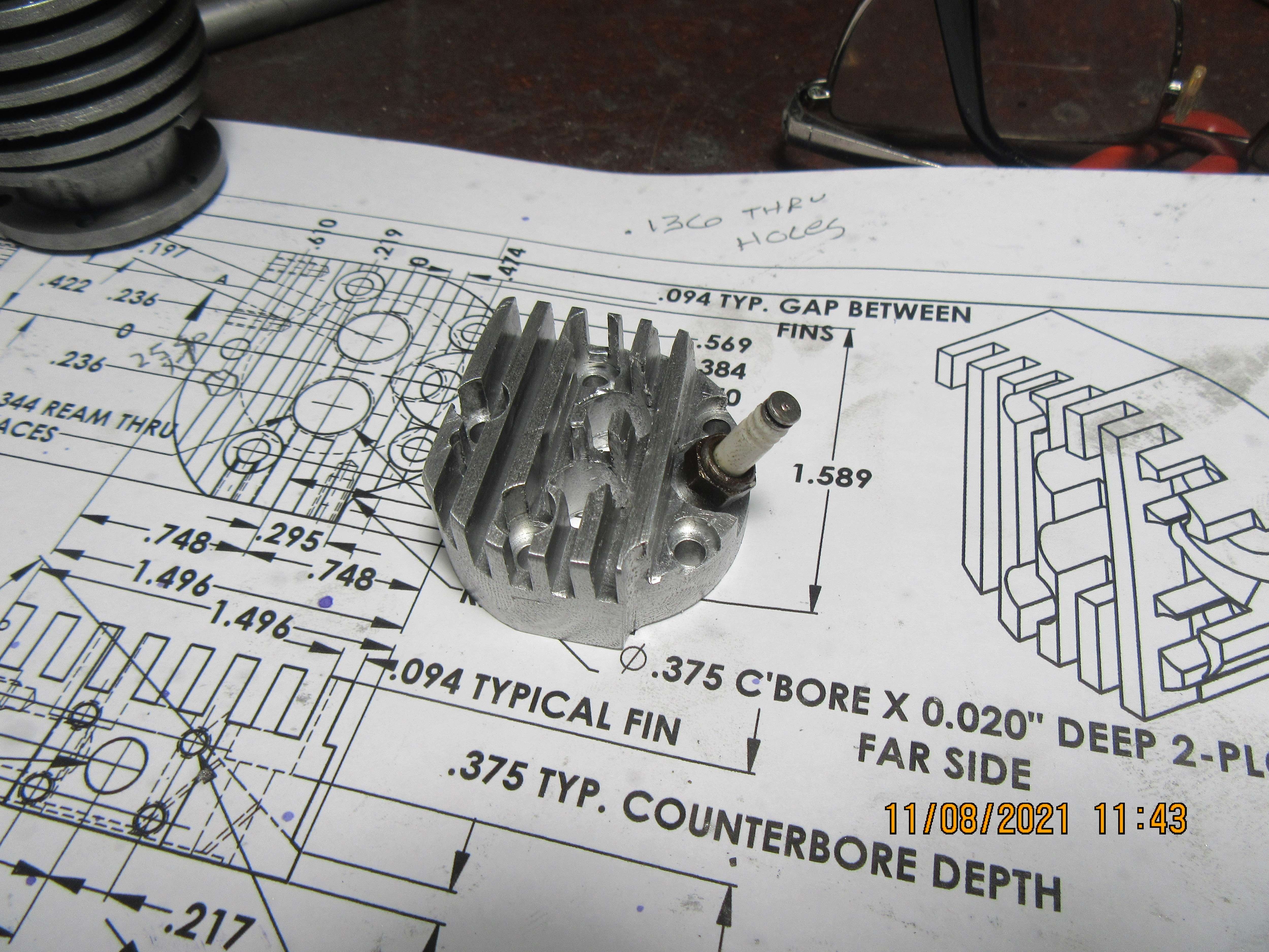
There is a lot of work to this cylinder head, and I am only about half done with it. However, it's a beautiful day here, sunny and 64 degrees F, so I'm going to put my tools away and take my good wife somewhere for lunch. This is probably one of the nicer days that November will offer, before we have snow up to our armpits. The slots were cut with a slitting saw.
BBWYpe.jpg
 
Brian: You are making the rest of us look bad. Taking on paying work. Taking your wife out for lunch. Fortunately my wife does not look at this forum.
 
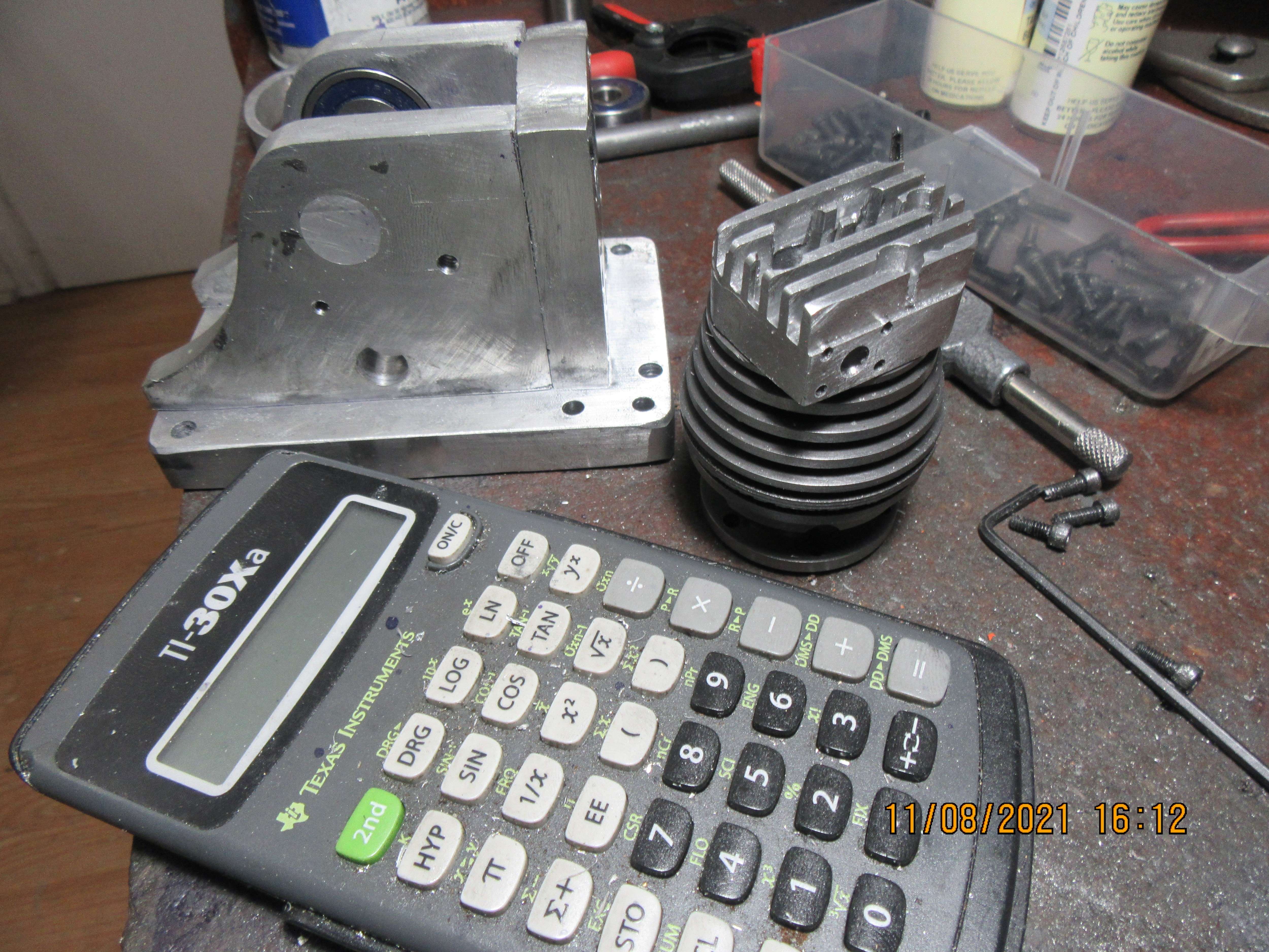
So here we have most of a days work. I took good wife out for lunch, then came back and started laying out, drilling, and tapping holes and the main 1" counterbore in the cylinder head. So far, so good. I am rather amazed at how small this thing is. That's a standard size pocket calculator laying in the foreground to give you some ides of a size comparison.
7OoufV.jpg
 
Gordon--I like the paying work thing. That way I don't feel guilty spending the grocery money on tools and material. I wouldn't want to be doing it all the time (I did it for 50 years full time). Now I just take a contract once in a while from one of my old customers.
 
Brian, I followed your fine example and took my wife out in the car to see some ships arriving in the river Tyne. Escorted by 3 tugs. The ship that is, not my wife, she only had me for escort. Pub was closed so we came home without a glass or 2 or our favourite refreshment.
Then I re-tuned the carbs on the motorbike, after shaving 0.5mm (0.020in.) off the air slides this morning with the miller. (Precise to a 50th of a mm). Checked with colour-tune plug and a little less rich than before. When it is dry I propose a few trips around town to check the slow running, where I have changed the carbs. Models are just so much easier than bikes!
K2
 
I have scrapped the old "Rupnow Engine" that I built about 10 years ago, and am gradually salvaging the parts. I have two bronze flywheels that are the right diameter, and I'm thinking of salvaging the outer rims and turning new aluminum centers. I have never made solid flywheels with no holes in them, and I'm thinking of doing that. Many of the old hit and miss water cooled engines had solid webs in the flywheels---I remember. If I don't like them I can always add holes in the webs later. What do you think?
BRqHXy.jpg
 
Brian,
Try it with the solid flywheels, and if too heavy, you can lighten them, bit harder to put the weight back on after
Still watching.
Cheers
Andrew
 
Hi Brian, I think your illogical, design it as you go, methodology is crazy! But you are brilliant in how you create unusual and very good models that way. Shows the depth of your skill and understanding.
Go for the plain flywheels, that can have very thin webs, as stresses are spread around so uniformly. But with thin webs, you can't fit a belt drive onto the outer rim... That needs a thicker web to cope with the bending stresses, or spokes.... will the flywheel rims drive fans or generators or pumps?
K2
 
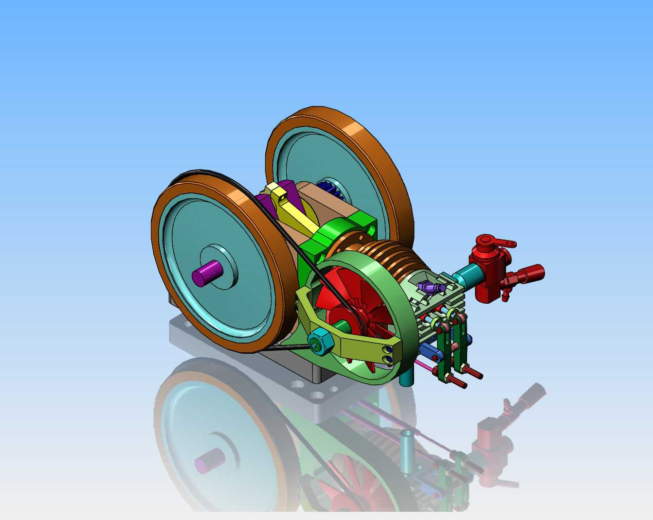
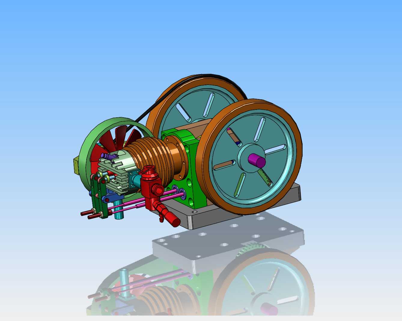
I've decided I don't care that much for the solid flywheel web. I have an idea that is easy to machine and makes the flywheel action more visible as they turn. I think this will be what the finished flywheels look like.
Mh4pCM.jpg
 
Today was intake and exhaust day. I had just enough brass around the shop to make these two assemblies. I have to go buy some more 1/2" diameter brass rod to make tappet guides and valve cages with. All or at least most of the brass will get polished as I get deeper into this engine.
5miCwx.jpg
 
Brian,
Have been following your work, please continue to update. Looking forward to seeing what it looks like in the end. Great engine.
Cheers
Layne
 
I looked at your picture which showed the brass rocker arm pivot and my first thought that you were designing it to plug into an electrical outlet. :)
 
Brian:

If you want to get really ambitious when you make the flywheels, you could always add a pair of self-folding handles to make "Hand" cranking the engine easier. At this scale they probably be next to useless, but it's the thought that counts right?

Don
 
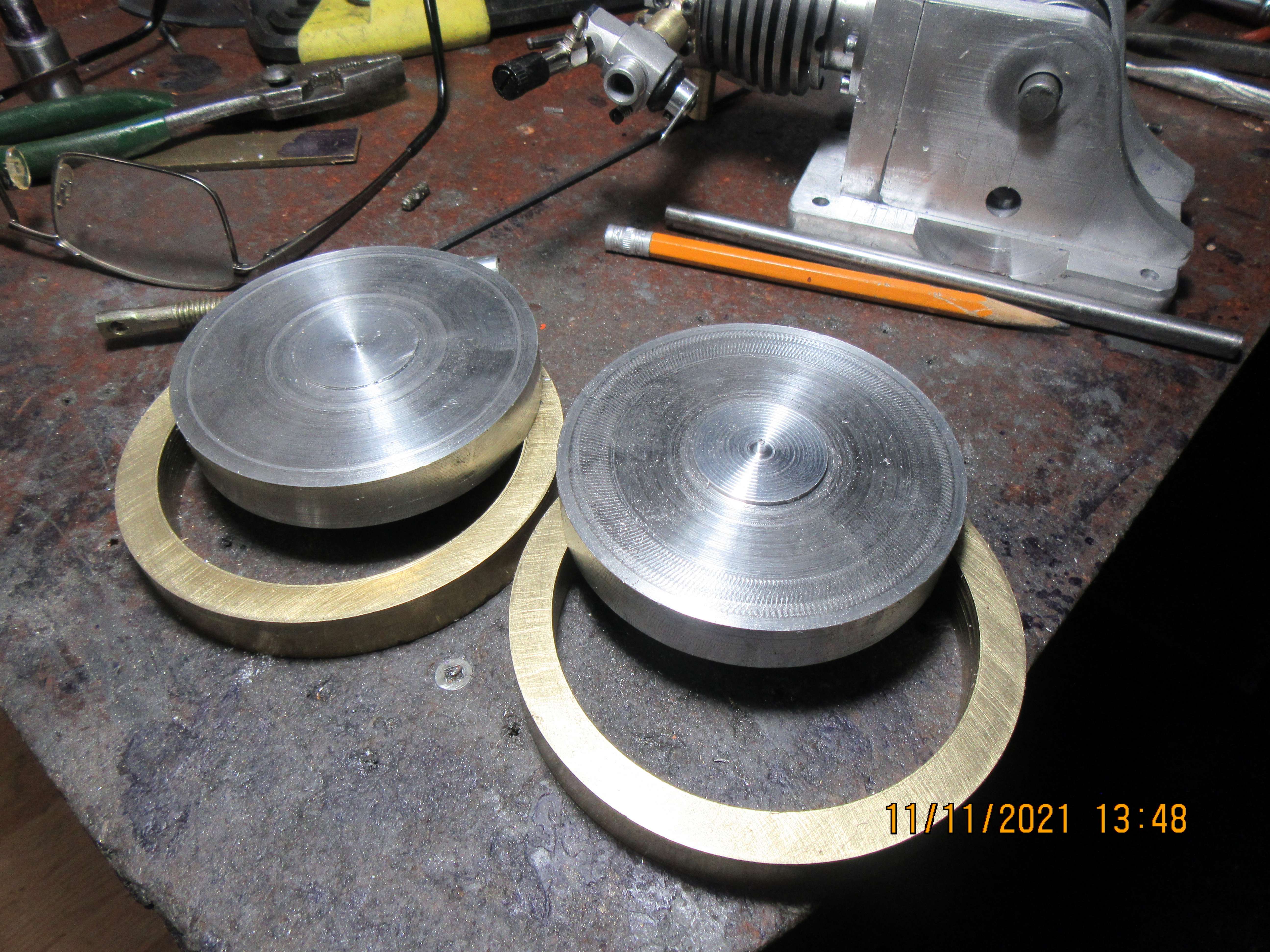
The morning was spent cutting out the centers of the brass flywheels on the old Rupnow Engine to give me two nice outer rims for my new flywheels, and cutting two aluminum centers from a piece of 3 1/2" diameter aluminum that I had left over from another project. I still have miles to go before I sleep, but so far things are looking good.
2YLNrZ.jpg
 

Latest posts

Back
Top