Gearless Mechanism--4 stroke i.c. engine

Home Model Engine Machinist Forum

Help Support Home Model Engine Machinist Forum:

This site may earn a commission from merchant affiliate links, including eBay, Amazon, and others.

Brian Rupnow

Design Engineer
Project of the Month Winner
Joined
May 23, 2008
Messages
15,249
Reaction score
8,525
Location
Barrie, Ontario, Canada
I have long been fascinated with the old hit and miss engines that were 4 cycle engines, but used no gear to drive the cam shaft at half the speed of the crankshaft. I have studied on this, and they break down into two main types. The kind I can not reproduce on a manual mill is the type which had cam tracks cut into the face or periphery of a disc. Chuck Fellows did a really nice job of reproducing one of those last year. The other type, which I can reproduce on my manual machinery, is the "star wheel" type. I don't want to start another engine build right now. However, I will attempt to create one of the mechanisms, post drawings of how I made it, and build the mechanism and make a video of it operating. I might fall on my face here, but follow along if you are interested. The one I make will be sized to work on a model engine.
 
Brian, I cannot see a reason why the Chuck Fellow cam type could not be made with circular arcs on a rotary table. Granted it may be a self scalp depilatory experience, but we are not afraid to take a machining challenge, are we?
 
Brian, I cannot see a reason why the Chuck Fellow cam type could not be made with circular arcs on a rotary table. Granted it may be a self scalp depilatory experience, but we are not afraid to take a machining challenge, are we?
Tornitore--if you think it can be done on a manual machine, then go for it. I don't think I could.---Brian
 
Always interested in your projects Brian.
 
I can see that you are keen to use the new mill on another project. I will follow along with great interest.

Paul.
 
These mechanisms seem to do a lot better with a roller on the end which rides on the cam. I am assuming that this is because #1--it will be moving twice as many times in a complete cycle as a lifter which runs off a camshaft---and #2---it will be moving twice as fast, and #3--it has more mass than a standard "valve pushrod".
 
Hello there Brian-

So happy to see that you are undertaking the challenges of redesigning, revamping, and improving, this type of 2:1 "GEARLESS" reduction mechanism.

Hope you also will do some work regarding the inertia governor mechanism that controls the exhaust valve events.

Good luck with this interesting project, and thanks for sharing your thoughts, renderings, and insight.


Frank
 
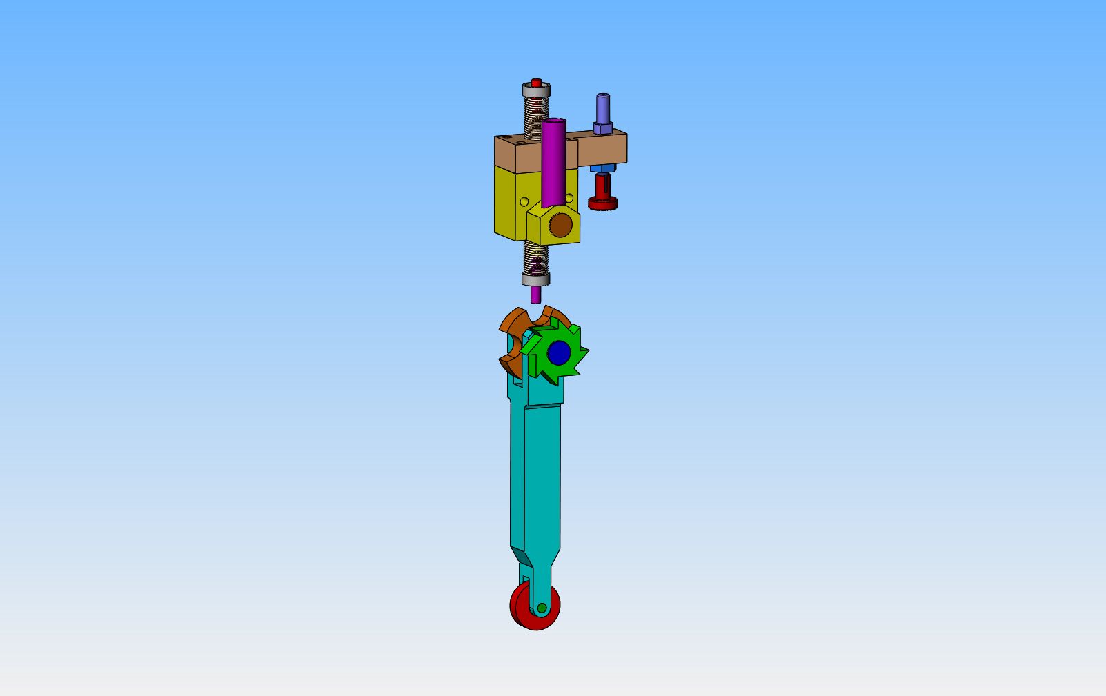
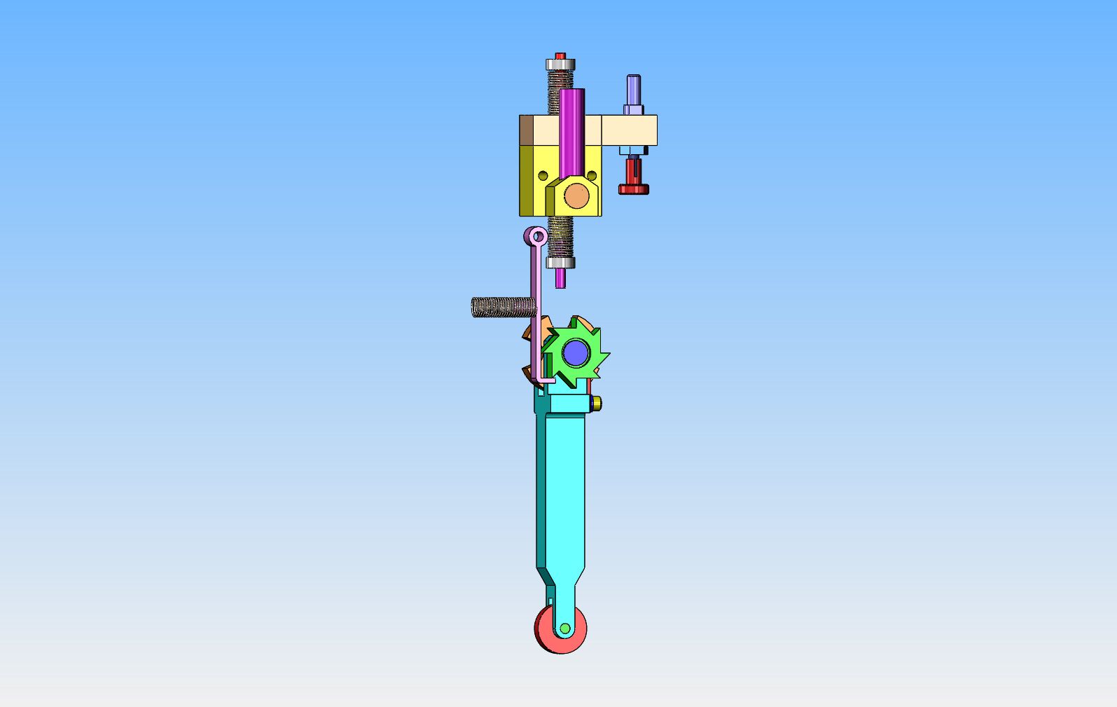
At this point, I have to decide whether the engine cylinder will be horizontal or vertical. The gearless mechanism will work on either, but for illustration purpose, I will use vertical. I also needed to show the exhaust valve that will be acted on (the intake valve is atmospheric)----and what better to use than the valve body/carburetor that I so recently designed for the oscillating i.c. engine.
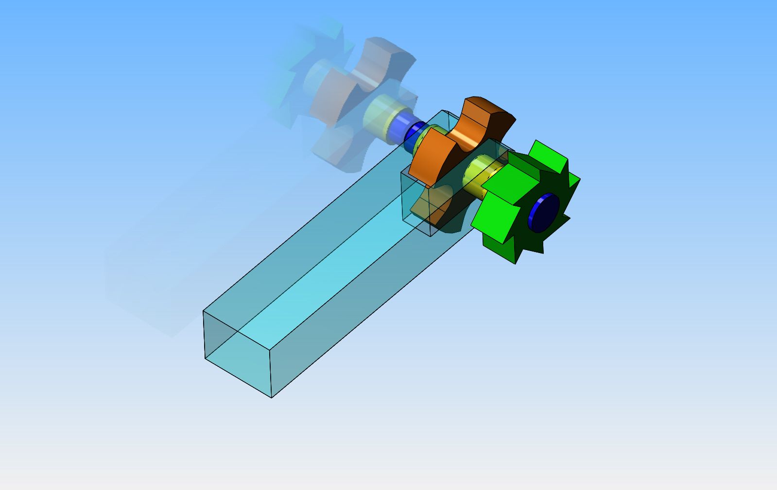
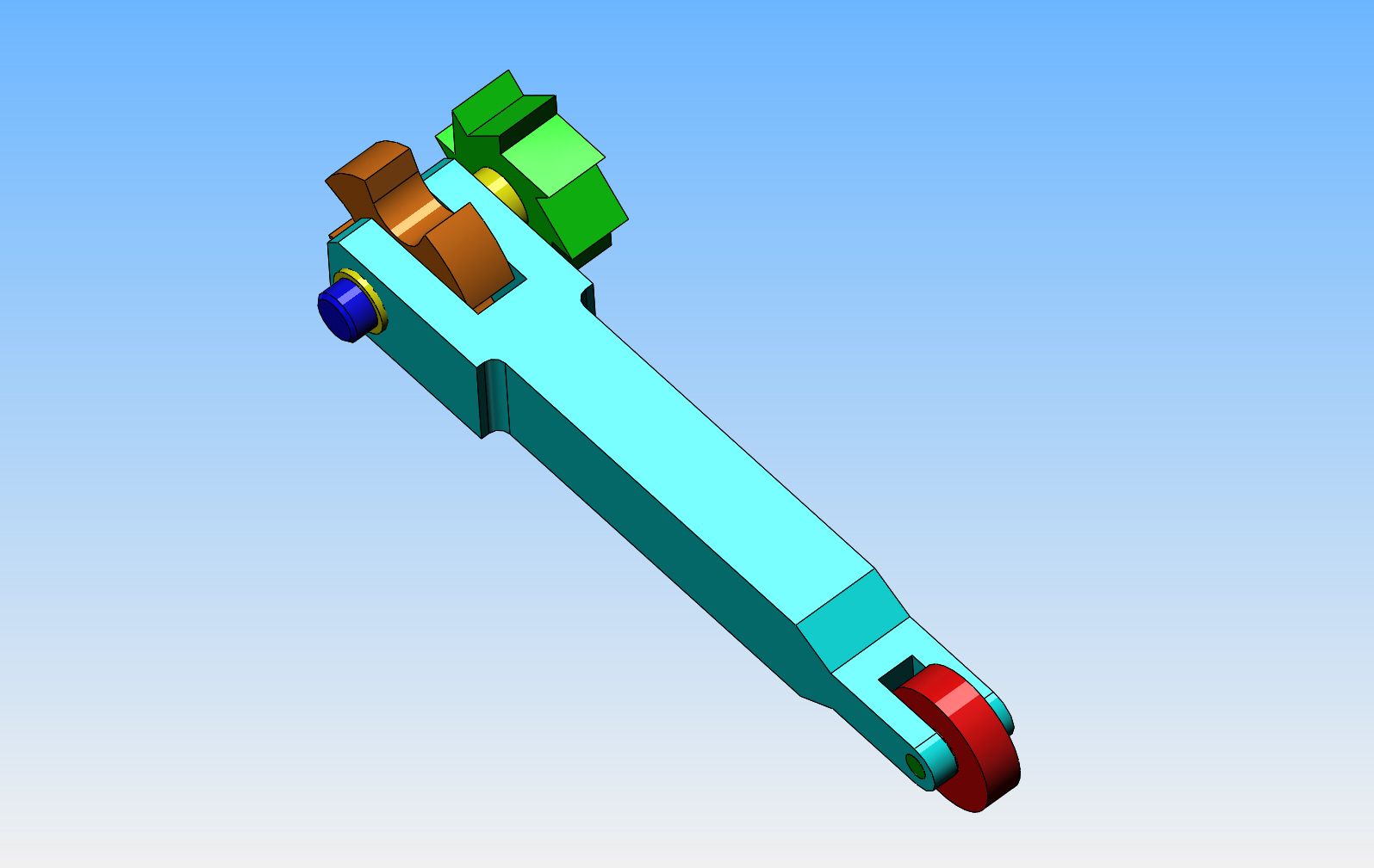
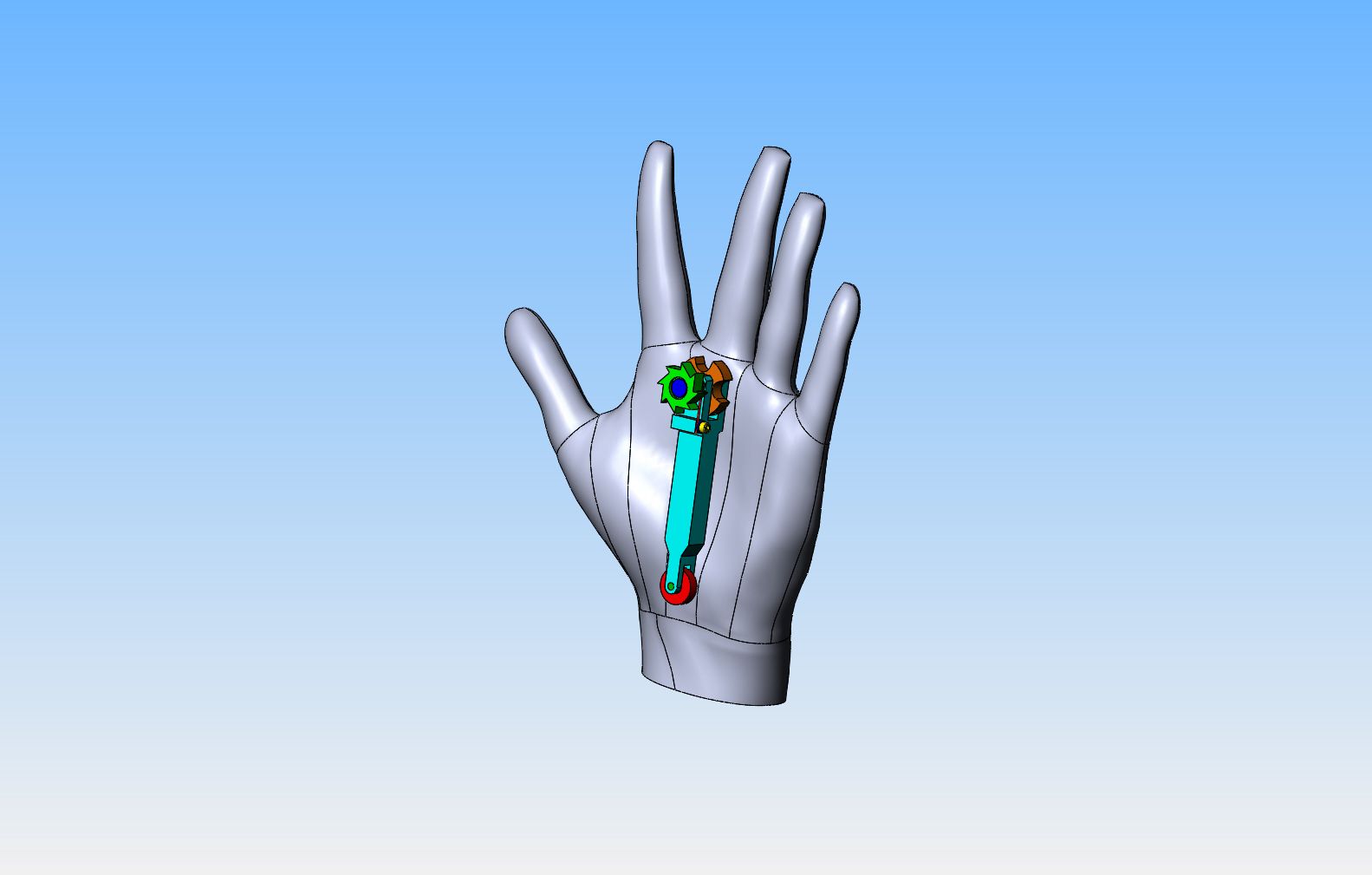
----Now, to get into the science of how this thing works. Immediately below the stem of the exhaust valve, you will see the 4 lobed brown "star wheel". This star wheel has 4 "lobes" that will contact the bottom of the exhaust valve and lift it, if the entire gearless mechanism is lifted on a cam. It also has 4 "relieved areas" between the "lobes" (as shown) which will NOT contact the valve stem if the star wheel gets rotated 1/8 (22.5 degrees) before it gets lifted again!! So--Stay with me--the cam is attached to the crankshaft. That means that with every single revolution of the crankshaft, that gearless mechanism will lift up on the cam lobe and then return to the "down" position--(There will be a tension spring attached to the gearless mechanism to ensure that it does return to the "down" position and stay in contact with the cam. So---as long as we are able to rotate that star wheel 1/8 of a turn every time the mechanism goes up and down then the valve will only get lifted EVERY OTHER time the gearless mechanism is lifted.--That nifty looking green ratchet wheel with 8 notches on the same shaft as the star wheel is the component which ensures this will happen.
 
Last edited:
Hello there Brian-

So happy to see that you are undertaking the challenges of redesigning, revamping, and improving, this type of 2:1 "GEARLESS" reduction mechanism.

Hope you also will do some work regarding the inertia governor mechanism that controls the exhaust valve events.

Good luck with this interesting project, and thanks for sharing your thoughts, renderings, and insight.


Frank
Frank--By "inertial governor" are you talking about the "centrifugal governor" as used on hit and miss engines?---if so, no, I am only covering the gearless mechanism in this thread. If you want to see a centrifugal governor controlling the exhaust valve events, then look at the build thread I just finished on the "oscillating i.c. engine". It is a hit and miss with a centrifugal governor on it.---Brian
 
Toolguy raises a very good point.--What keeps the star wheel and ratchet wheel from drifting out of the proper rotational relationship to the valve stem. I have seen it done two ways, and know of a third. The third way which I know of, is a spring loaded detent ball and eight detents in either the star wheel or the ratchet wheel. This might work fine for something that only sees occasional use and slow moving components, but it wouldn't live with something like this application. I have seen the following method used on a model---A piece of rubber or vinyl tubing is slipped over the axle between the ratchet wheel and the blue "fork" supporting it, and is a bit longer than the actual space provided there. This acts as a friction brake to keep the star wheel from rotational drifting out of alignment. The third way, which is used by Philip Duclos on his gearless engine design, it to have a piece of spring wire laying tight against the flat face pf an 8 sided octagonal wheel which rotates with the star and ratchet wheel. When the star wheel and ratchet wheel and octagonal wheel rotate, the spring wire is bent away from the flat it lays against and after the 22.5 degrees of rotation another flat face is presented and the spring wire snaps into place against the flat to keep it from drifting rotationally until the next cam action turns it again. I like the Philip Duclos method best, and will investigate it farther---The only thing I don't like about it is that it begins to get very "busy" around the star wheel. If anyone out there knows of a better/different way, please step forward and tell me about it.---Brian
 
I just found this video, which shows the action of the starwheel very clearly at 2:18 into the video.
[ame]https://www.youtube.com/watch?v=dneJKmdRbu8[/ame]
 
Last edited:
Hello Brian- and others....

Very interesting to see and read about this star-ratchet mechanism. The video shows it all, including the spring loaded/adjustable, governing mechanism. Maybe my references to "intirtal governor" was the wrong term to use for this set-up.

The Olds Vertical Gearless, I'm pretty sure, uses a a weighted, "inertial" (??) governor that reciprocates, or "bobs" up and down, along with the star ratchet, which in turn, also controls the latching mechanism, that allows the exhaust valve to be either be held open at higher speeds, or to close and open at lower engine speeds. The governor, and spring combination, can also be adjusted to kick in/latch-unlatch at different RPMs.

Wish I was as good at giving explanations as you, and some of the other engine builders, who post on this forum. Also wish I could provide link ups with videos showing the Olds Vertical Gearless in action - along with its simple, easily machined, governing mechanism.

Can't wait for your next installment.


Frank
 
The preceding video shows a couple of really top notch ideas that I have been wondering about. First, instead of a spring holding the gearless mechanism in contact with the cam, the large end of the rod which runs to the cam totally encircles the cam, similar to early steam engine valve rods. This means that no spring is needed. The revolving cam can now not only push the rod in it's upward travel. but also pull it back down again. Secondly, instead of some strange shaped cam, the cam is a perfect circle, simply offset by some calculated amount from the central axis of the crankshaft. And---(best of all) it has a true ratchet and pawl system to turn the ratchet wheel with a nice positive action, and then hold it by spring pressure to prevent rotational drift of the star wheel.
 
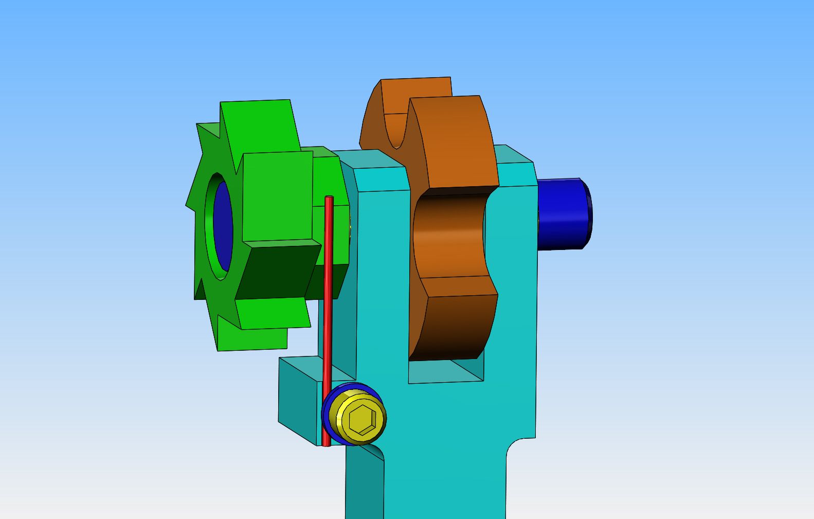
I have decided to use the Duclos method to keep the star and ratchet wheel from getting out of rotational position. I have machined an 8 sided shape onto the side of the ratchet wheel and used a piece of .030" diameter spring wire (in red) held in place by a washer (dark blue) and #4-40 shcs. (yellow). When the ratchet wheel is forced to rotate 45 degrees (by a mechanism not yet shown), the wire will spring away, then snap back into place against the next flat face. The light blue "fork" that supports the star and ratchet wheel has had a small "ear" added to one side to provide a place for the #4-40 shcs to thread into. It also has a very slight groove machined into it for the .030 wire to set in to keep it from moving.
 
Last edited:
I'm getting to the "hinky" part of this design now. Assume for a moment, that the gearless mechanism has not yet stopped moving down---The star wheel is clear of the bottom of the valve-stem so it can rotate, but it hasn't rotated yet. The spring loaded pivoting "pawl arm" is swung in by the spring pushing on the back of it and you can see that the bent end of it is going to catch the tip of the ratchet wheel below the centerline of the ratchet wheel. If my downward travel is calculated correctly, then when the gearless mechanism continues it's downward travel and is fully bottomed out, the ratchet wheel and consequently the star wheel is going to be rotated by an amount equal to 45 degrees of rotation. --When that happens, then the gearless mechanism will move upwards due to influence from the cam, and since it has rotated 45 degrees, one of the lobes on the star wheel is going to contact the stem of the valve and lift it.---Clear so far??:eek::eek:
 
Last edited:
Hello Brian- and others....

Very interesting to see and read about this star-ratchet mechanism. The video shows it all, including the spring loaded/adjustable, governing mechanism. Maybe my references to "intirtal governor" was the wrong term to use for this set-up.

The Olds Vertical Gearless, I'm pretty sure, uses a a weighted, "inertial" (??) governor that reciprocates, or "bobs" up and down, along with the star ratchet, which in turn, also controls the latching mechanism, that allows the exhaust valve to be either be held open at higher speeds, or to close and open at lower engine speeds. The governor, and spring combination, can also be adjusted to kick in/latch-unlatch at different RPMs.

Wish I was as good at giving explanations as you, and some of the other engine builders, who post on this forum. Also wish I could provide link ups with videos showing the Olds Vertical Gearless in action - along with its simple, easily machined, governing mechanism.

Can't wait for your next installment.


Frank

Frank you were correct; what you are referring to is an inertia governor, or what us old engine guys commonly refer to as a pendulum governor.

Seems that it was used on some of the better quality engines of the day; like Deutz, Olds and lots of others.


Dave
 

Latest posts

Back
Top