You are using an out of date browser. It may not display this or other websites correctly.
You should upgrade or use an alternative browser.
You should upgrade or use an alternative browser.
Flyball Governor running on my steam engine
- Thread starter Brian Rupnow
- Start date

Help Support Home Model Engine Machinist Forum:
This site may earn a commission from merchant affiliate
links, including eBay, Amazon, and others.
- Joined
- Jun 4, 2008
- Messages
- 3,291
- Reaction score
- 635
:bow:
dsquire
Well-Known Member
- Joined
- Mar 18, 2008
- Messages
- 980
- Reaction score
- 15
Brian
Job well done. It looks like it came off the drawing board and went to work just about like it was supposed to. Doesn't look like you need much fine tuning with this. Have a drink on me Brian. :bow: :bow:
Cheers
Don

Job well done. It looks like it came off the drawing board and went to work just about like it was supposed to. Doesn't look like you need much fine tuning with this. Have a drink on me Brian. :bow: :bow:
Cheers
Don

Bernd
Well-Known Member
Very good Brian. I see that the fly balls are doing exactly what they are supposed to, but the engine is not doing what the fly ball governor is telling it to do. If you have ever observed a traction engine belted up to a saw mill you would see that the fly ball governor is used to keep the engine at a constant speed under varying loads. The flay balls on your engine my open the valve to give more pressure but the engine is not keeping a constant speed. It is hard to scale down the dynamics of such an engine and have it work like the real steam engine. Perhaps it would work different using steam instead of air.
The flay ball governor is the mechanical cruise control of the steam engine.
Again nice job on that governor. :bow:
Bernd
The flay ball governor is the mechanical cruise control of the steam engine.
Again nice job on that governor. :bow:
Bernd

$649.00
$699.00
FoxAlien Masuter Pro CNC Router Machine, Upgraded 3-Axis Engraving All-Metal Milling Machine for Wood Acrylic MDF Nylon Carving Cutting
FoxAlien Official

$190.00
$254.99
Genmitsu CNC 3018-PRO Router Kit GRBL Control 3 Axis Plastic Acrylic PCB PVC Wood Carving Milling Engraving Machine, XYZ Working Area 300x180x45mm
SainSmart Official

$104.99
Sunnytech Hot Air Stirling Engine Motor Steam Heat Education Model Toy Kit M16-CF
stirlingtechonline

$403.09
DM14 Engine Build Kit, Metal Engine Build Model Great Metal Material for Engineer for Factory
Easoger Official

$94.99
$109.99
AHS Woodmaster 4400 Maintenance Kit for Outdoor Wood Boiler Treatment
Alternative Heating & Supplies

$45.99
Sunnytech Mini Hot Air Stirling Engine Motor Model Educational Toy Kits Electricity HA001
stirlingtechonline

$54.46
Amana Tool - 46280 CNC 2D & 3D Carving 6.2 Deg Tapered Angle Ball Tip x 1/32 Dia x 1/64
Express Tool Supply

$15.99 ($0.05 / Count)
$18.99 ($0.06 / Count)
HongWay 300pcs 2 Inches Sanding Discs Pad Kit for Drill Sanding Grinder Rotary Tools with Backer Plate Shank and Soft Foam Buffering Pad, Sandpapers Includes 60-3000 Grit
HongWay US

$99.99
$109.99
AmTech300 - Boiler Treatment Professional Strength (Rust Inhibitor For Outdoor Wood Boilers)
Alternative Heating & Supplies

$188.98
TM NEXDYNAMI RE41157 Water Pump Compatible With/Replacement For/John Deere 6200 7400 6300 6600 6500 6400 7220 7600 7200 RE41157
VIVID MARKET CORPORATION

$39.99
$49.99
Sunnytech Low Temperature Stirling Engine Motor Steam Heat Education Model Toy Kit For mechanical skills (LT001)
stirlingtechonline

$59.99
Sunnytech Hot Air Stirling Engine Motor Model Educational Toy Electricity Generator Colorful LED (SC001)
stirlingtechonline
Bernd said:Very good Brian. I see that the fly balls are doing exactly what they are supposed to, but the engine is not doing what the fly ball governor is telling it to do. If you have ever observed a traction engine belted up to a saw mill you would see that the fly ball governor is used to keep the engine at a constant speed under varying loads. The flay balls on your engine my open the valve to give more pressure but the engine is not keeping a constant speed. It is hard to scale down the dynamics of such an engine and have it work like the real steam engine. Perhaps it would work different using steam instead of air.
The flay ball governor is the mechanical cruise control of the steam engine.
Again nice job on that governor. :bow:
Bernd
I'm pretty sure that was happening because I was only running at 40 PSI. If I was running at 100 PSI for instance, as soon as the load come on, and the flyball moved to allow more flow into the engine through the valve, the higher pressured air rushing in would keep the engine from slowing down. You are right--it is difficult to scale down some of these actions/reactions.
mklotz
Well-Known Member
Very nice work, Brian. Stick your chest out and be proud.
Now that we've got all the fly-ball experts in a huddle, I have a question - something that bothered me when I built the governor on Elmer Verburg's rope drive engine.
Brian's valve has a (round) hole that, as the valve slides, covers/uncovers the (round) holes in the valve body to modulate the air flow.
This arrangement means that, to first order, the valving action is non-linear. Depending on the valve rod position, the change in opening size for a small change in valve rod postion will not be constant.
My question is: Does this matter and, if so, what are the implications? Can anyone with full-size governors tell us how the valving action is accomplished on real governors?
OK, two questions. (I've gotta work on that counting thing. )
)
Now that we've got all the fly-ball experts in a huddle, I have a question - something that bothered me when I built the governor on Elmer Verburg's rope drive engine.
Brian's valve has a (round) hole that, as the valve slides, covers/uncovers the (round) holes in the valve body to modulate the air flow.
This arrangement means that, to first order, the valving action is non-linear. Depending on the valve rod position, the change in opening size for a small change in valve rod postion will not be constant.
My question is: Does this matter and, if so, what are the implications? Can anyone with full-size governors tell us how the valving action is accomplished on real governors?
OK, two questions. (I've gotta work on that counting thing.
Marv---If you take a look at the blown up solid models on this thread, you will see that the round hole in my valve rod is actually a slot!!! I had the same thought that you are having.---Brianmklotz said:Very nice work, Brian. Stick your chest out and be proud.
Now that we've got all the fly-ball experts in a huddle, I have a question - something that bothered me when I built the governor on Elmer Verburg's rope drive engine.
Brian's valve has a (round) hole that, as the valve slides, covers/uncovers the (round) holes in the valve body to modulate the air flow.
This arrangement means that, to first order, the valving action is non-linear. Depending on the valve rod position, the change in opening size for a small change in valve rod postion will not be constant.
My question is: Does this matter and, if so, what are the implications? Can anyone with full-size governors tell us how the valving action is accomplished on real governors?
OK, two questions. (I've gotta work on that counting thing.)
I just posted a complete set of engineering drawings for this governor in the uploads section, in .pdf format. You are welcome to use them--if you download them I would appreciate a karma point. Its a fun project.---Brian
Brian, you did it again, I don't know about the do and don't and what is suppose to be or not to be but you have proof that it works, not like your going to the moon either, I say you did great and not only that you know how to share, teach and encourage others, I for one am thankful, going to the down load now, some day I will try to do that, thanks teacher, Lathe Nut
Bernd
Well-Known Member
mklotz said:My question is: Can anyone with full-size governors tell us how the valving action is accomplished on real governors?
Edited to just the one question Marv had.
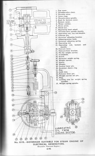
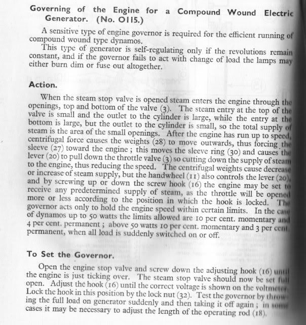
Here's a pic from "Stean Engine Priciples & Practice" from 1922. A book reproduced by Lindsay Publications.

And here's what it would look like sitting on top of 110HP Case traction engine.

Hope this helped Marv. There's more to this governor thing that can be published here.
Bernd
Metal Mickey
Well-Known Member
- Joined
- Jul 5, 2008
- Messages
- 612
- Reaction score
- 6
Very interesting thread and a good instructional video. Enjoyed the ride as it were. Seeing it come off the CAD to the machine....good st :bow:
ChooChooMike
Well-Known Member
- Joined
- Jan 5, 2008
- Messages
- 863
- Reaction score
- 13
EXCELLENT BRIAN !! :bow: :bow: Love to see how you developed this from scratch !!
Similar threads
- Replies
- 4
- Views
- 429
- Replies
- 13
- Views
- 2K
- Replies
- 0
- Views
- 158


