Flathead hit and miss engine???

Home Model Engine Machinist Forum

Help Support Home Model Engine Machinist Forum:

This site may earn a commission from merchant affiliate links, including eBay, Amazon, and others.
Yes Gordon, I thought about that all ready. I've been going ahead with timing gears and camshaft position, but that doesn't keep me from turning the whole thing horizontal. I got a call from a customer about a design change on an automation job so had to stop at 2:30 and do some real work for a change.---Brian
 
Hootchie Mama!!!--I even found room in there for a pair of gears and a cam and a tappet and a tappet guide. Still haven't got the faintest idea of how to turn this into a hit and miss but it's going to need all of these parts anyways.
DtOFeZ.jpg
 
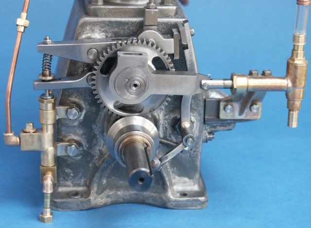
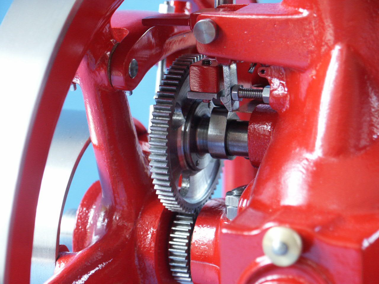
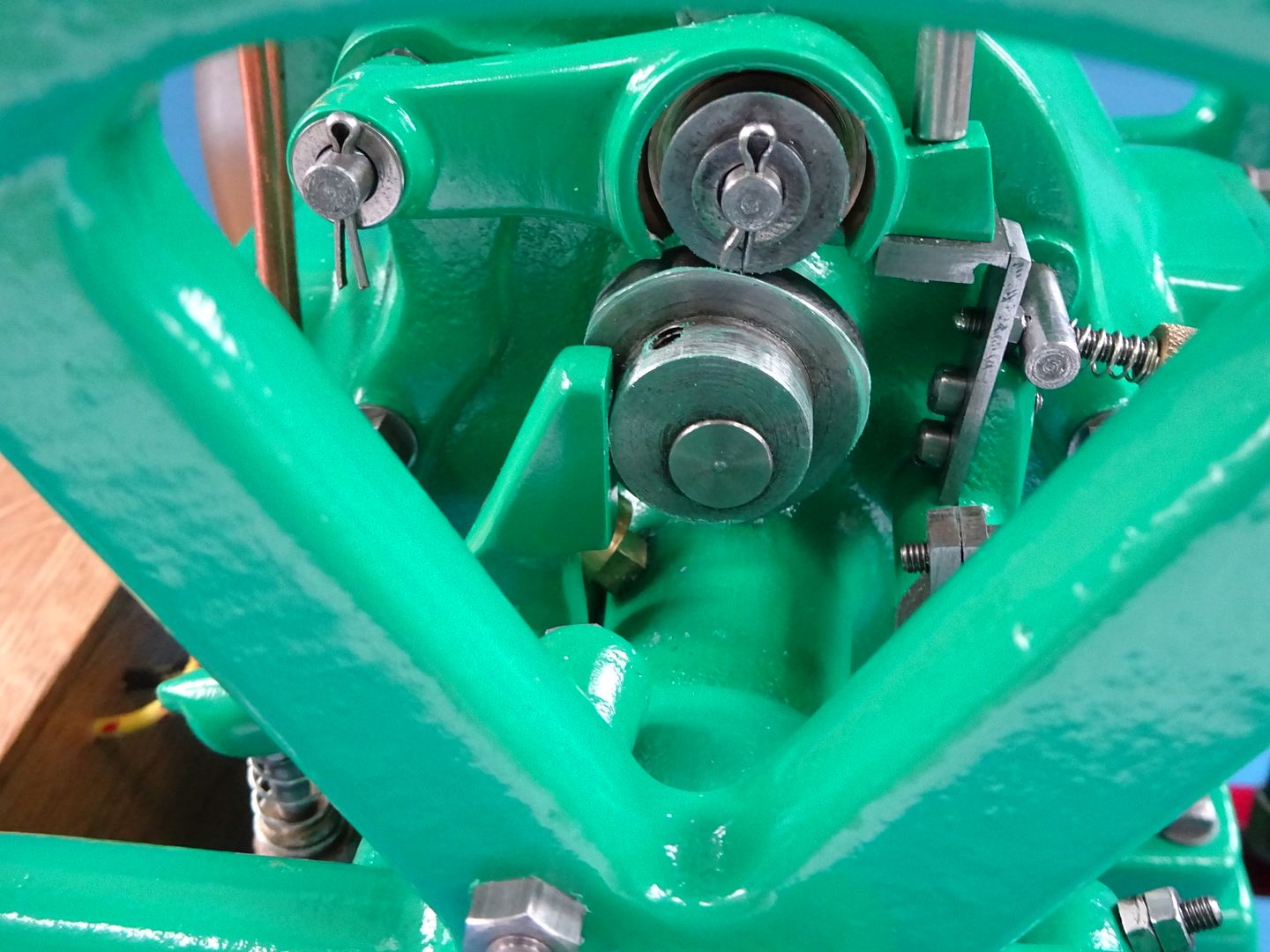
Brian, as for how to make it hit and miss, shorten that exhaust valve, have that cream coloured bar pivot on the right side of the crankcase, fit a roller follower in the middle and have your governor latch work on the left hand end as it rises up to push the exhaust valve. The VJ Monitor has a similar arrangement but the rocker arm is "L" shaped

Again ;look at many of the vertical hit and miss engines such as IHC, Monitor, Root & Van Dervoort

Regarding that rather tall crankcase, you could put the engine on legs or simply mount it on a wooded sled and let the flywheel overhang the side

Still interested to see a vertical section through that valve block as I'm not sure it will work as is, get that sorted first as it may affect other parts

PICT0338.jpg


PICT0476_zpsfdc3d52e.jpg


DSC03488_zpsh2fthvyt.jpg


VJ rocker.JPG
 
Last edited:
Jason--that cream colored bar is a tappet guide. It is fixed in position and the only purpose it serves is to guide the tappet.--thinking---thinking---What I have assumes the cream colored bar is fixed ad the red tappet is guided vertically by a hole thru that cream colored part. Do you mean to pivot that bar on the right hand side, with the tappet fixed in place in the cream colored bar? The hit and miss lever slides in under the left hand end of the pivoting cream colored bar to hold the exhaust valve open?
 
Last edited:
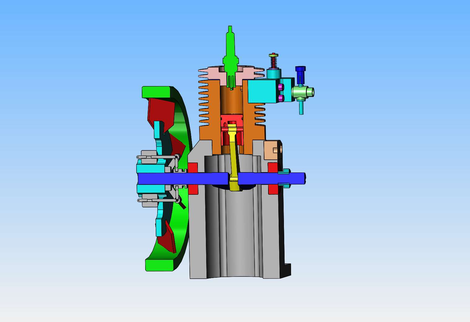
This is a cross section thru the engine at center. I have added the hit and miss mechanism between the flywheel and the crank case. I haven't yet decided how it's going to hold the exhaust valve open, but I'm closing in on it.
D1IMaw.jpg
 
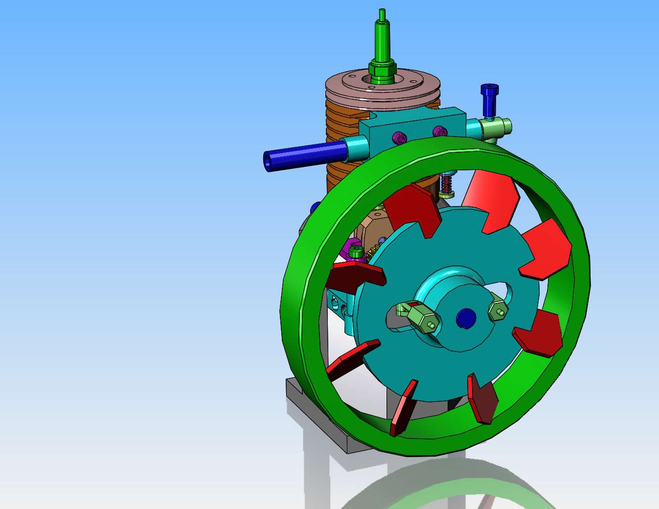
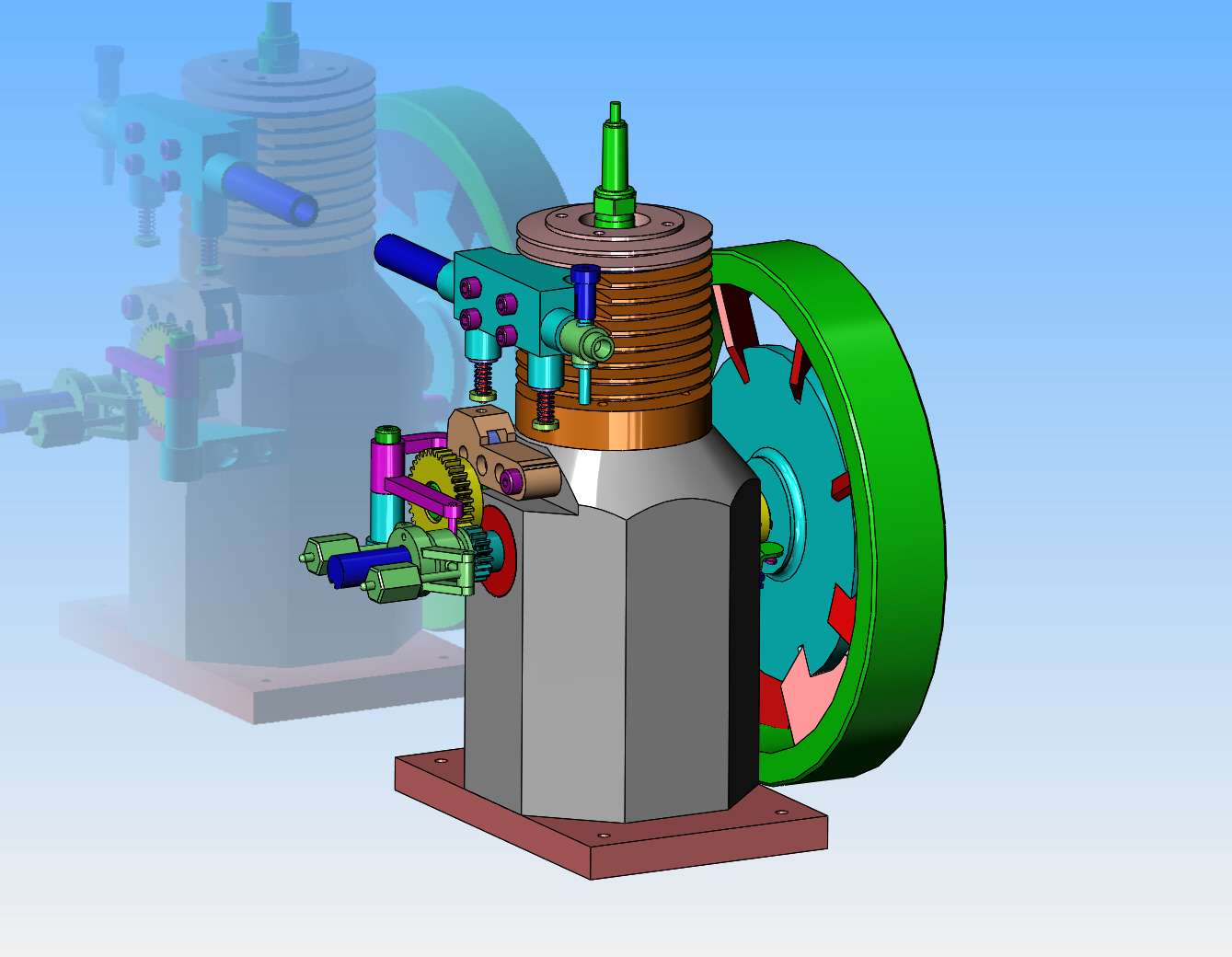
I'm pooched!! Flywheel and hit and miss mechanism have been moved to other side of engine, and various changes made to get a working hit and miss mechanism. Top manifold block will undergo some redesign tomorrow to reposition the carburetor and exhaust to clear the flywheel. Again, thanks very much to Jason for helpful suggestions.
yckyws.jpg
 
Hi Brian, The deep/tall crankcase reminds me of how the early engines had oil reservoirs beneath the crank, then a dip-rod projecting below the big-end of the con-rod, with a small lubrication hole in the big-end so the splash lubrication was driven up the dip-rod into the bearing lubrication hole.
I remember some rods (1960s repair shop) where I had to file a slight concave groove in the dip-rod to "encourage" more oil to run up the rod (that had been convex) to the lube hole. Supposedly to increase the oil supply to the bearing. Did it work? - WHO knows? I can imagine that the "splash" of oil inside the crankcase ensured everything was well covered in oil...
That aside, I think you need to decide if you want direct (straight-line action) from cams to valves, or a rocker cam follower (curved motion) to the push-rod, that gives you lots of scope as to location and hit 'n miss latch. Rockers are great for altering the mechanical advantage of the cam-to-push-rod motion, and to alter the line-of-action of cam contact to push-rod by being anything but straight. (Bent cranks go around corners!). The disadvantage is usually the moving mass (inertia) - But not in your case, as it is not designed as a "high speed" engine.
K2
 
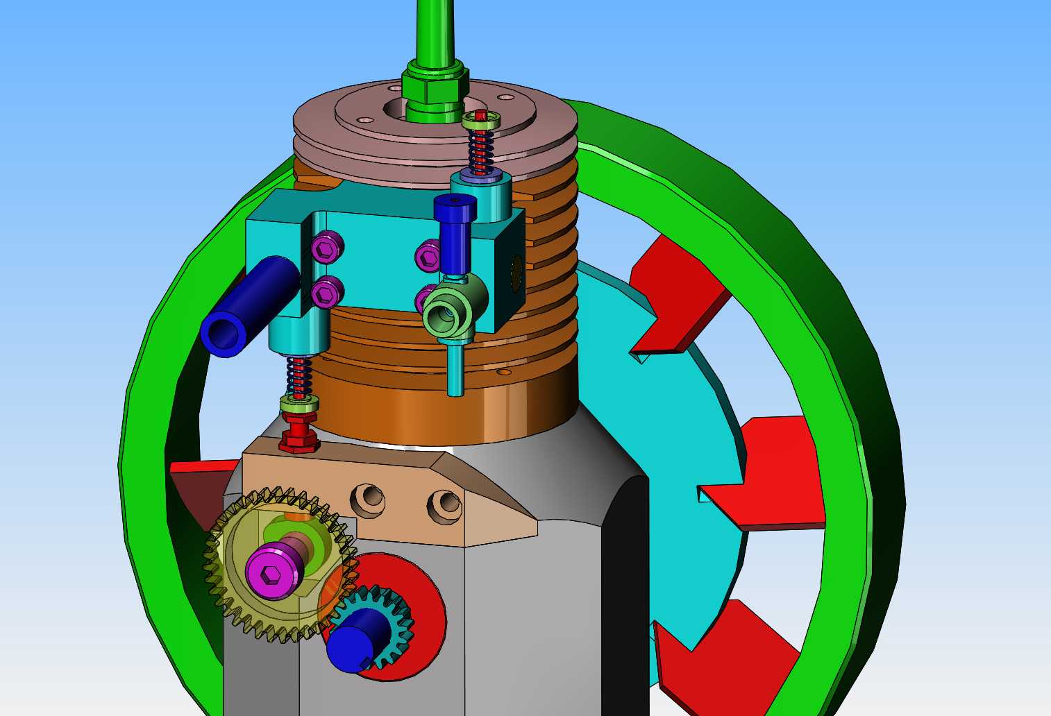
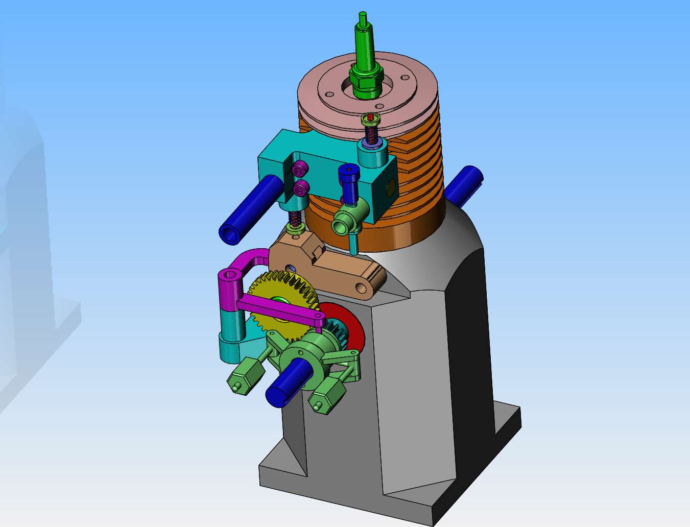
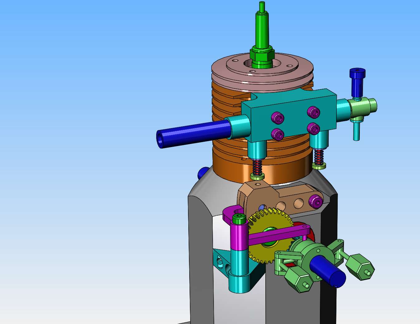
After a good deal of moving things around and about, I'm pretty sure I've got all the components arranged so that the hit and miss mechanism will work. This involved redesign of the intake manifold block, repositioning of the exhaust pipe and carburetor, and changes to the flywheel to tuck it in close to the engine. The light brown colored piece pivots on the right hand end and has a hardened wheel riding on the cam. The cam is attached to the yellow gear and they both spin on a 3/8" shoulder bolt. There will be a hardened convex shaped piece on top of the the light brown pivoting piece which contacts the end of my exhaust valve. The passion pink governor lever will pivot on a shoulder bolt and a 0.125" diameter rod welded to one end rides in the groove on the governor spool. At speed, when the governor weights swing out, the governor spool will move along the crankshaft causing the passion pink governor arm to pivot, and slide underneath the end of the pivoting light brown piece, thus preventing the exhaust valve from closing.
XvzVv7.jpg

2aMzuX.jpg
 
Chiptosser--I just did a web search for Foos engines, and yes, they apparently did make flathead hit and miss engines!!! Thank you for that. I had never heard of Foos engines before.---Brian
 
Hi Brian, The deep/tall crankcase reminds me of how the early engines had oil reservoirs beneath the crank, then a dip-rod projecting below the big-end of the con-rod, with a small lubrication hole in the big-end so the splash lubrication was driven up the dip-rod into the bearing lubrication hole.
I remember some rods (1960s repair shop) where I had to file a slight concave groove in the dip-rod to "encourage" more oil to run up the rod (that had been convex) to the lube hole. Supposedly to increase the oil supply to the bearing. Did it work? - WHO knows? I can imagine that the "splash" of oil inside the crankcase ensured everything was well covered in oil...
I like the exhaust valve holding-open arrangement - if it works!

K2
 
Sorry: OT banter follows. Disregard if you want.

"The passion pink governor lever..." Now, there's an engine part I didn't think I would read about this early in the morning. Just tickled my fancy to see it.

Brian, No negativity meant. I genuinely like your design work, your finished projects, your posts, and your write-ups. Keep it all up.

--ShopShoe
 
Shopshoe--Never thought you'd see an xxx rated engine design, did you!! Actually, I make the parts different colors so they stand out more clearly to me as I design. It's only one click of my mouse to do that, and it provides endless amusement for the folks that follow my designs.---Brian
 
This morning I had a change of heart about the flywheel location. The whole reason I went to such a large flywheel was to cool the cylinder and head. I had it blowing directly onto the manifold block, but that's no good. I want it to blow directly onto the cylinder fins. So---I stuck the ignition cam and points and the flywheel on the other side of the engine and decided to let the hit and miss mechanism just hang out in the wind.
oxbtqM.jpg
 
Yow!!!--It's a good thing that I got such a bargain on my new shop stool. I just ordered the material for my new flathead hit and miss engine this afternoon and it came to $150. that doesn't cover any of the purchased things like points, sparkplugs nor bearings.
 
The flat-head engine was designed so that it was easy to put the crank and cam in the block and operate the valves directly off the lifters without needing pushrods. A hit and miss engine would require all sorts of contortions to install and spring the valves in a flat head configuration, where as putting the vacuum operated valve in the head, and the pushrod operated valve, also in the head was a simple solution, and was easily maintained. Many early aviation engines still used a pushrod and valve in head configuration. When the flat-head configuration came into play the technology had changed/improved sufficiently that it was a simpler. easier to maintain design. The flat-head design was the norm up until the '50s, then there was a brief time of the L-head Intake in the head, exhaust in the block, used tHE same block as the flat-head and then the pushrod engine took over, and more recently the overhead cam.
 
kf2qd--And your point is???? I'm an old guy. I've owned flat head Fords. I've owned many, many overhead valve Chev's and Pontiacs. I've designed and built almost every kind of i.c. engine that there is. I've built at least 5 or 6 hit and miss engines with overhead exhaust valves. Up until this week, I had never heard of a flat head hit and miss engine, but someone told me about Foos hit and miss engines, and sure enough, they were a flat head hit and miss engine which I had never heard of before. I'm not designing new technology here, I just wanted to build an engine type I haven't built before.---Brian
 
Brian I have followed several of your builds in the past and you always give me new ideas for my future builds.
You now have me thinking of a design I haven't built before somewhat along the lines of this project. If I decide to make it I will start a new thread.
Thank you
Ray
 
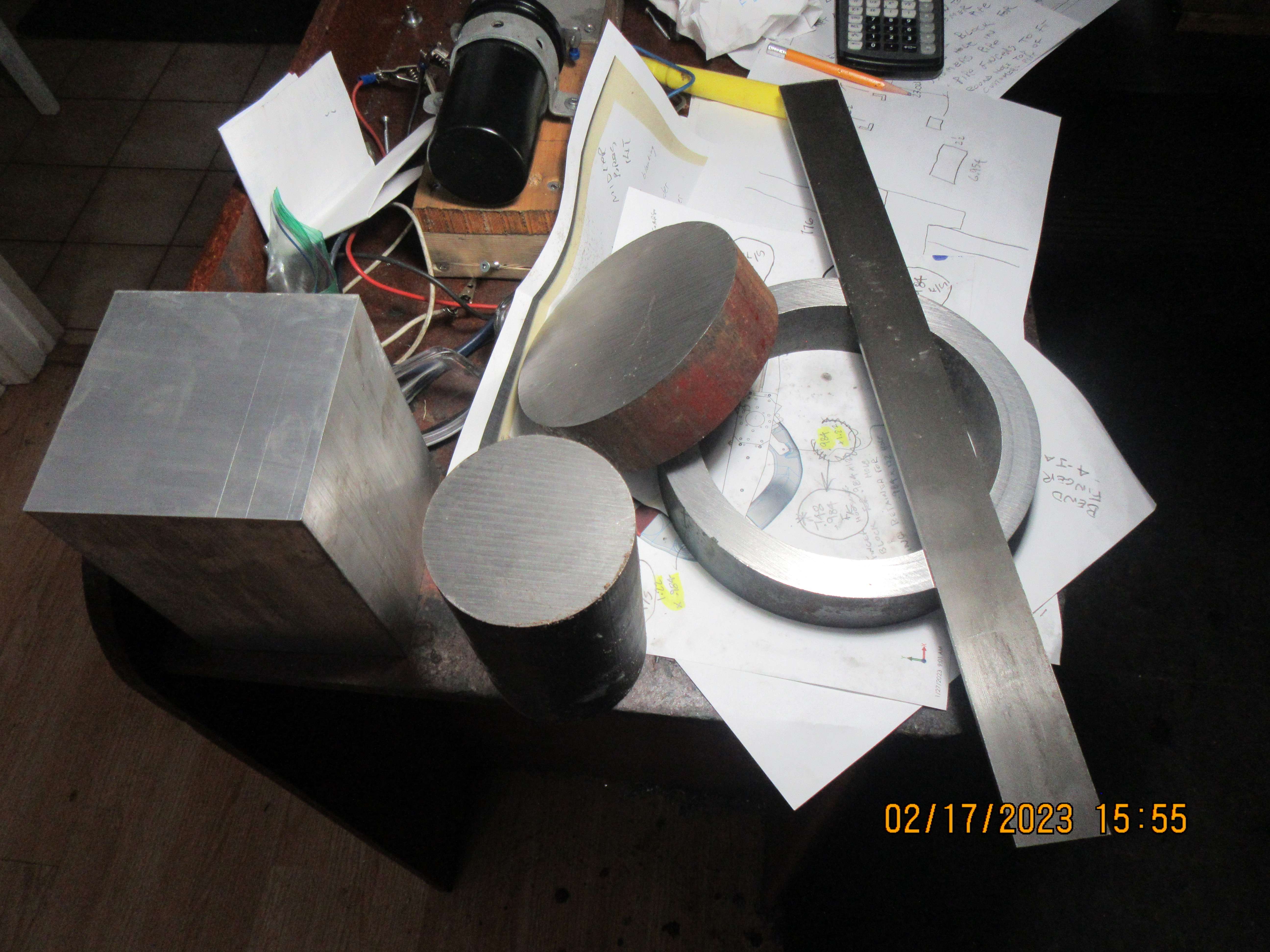
And this, boys and girls, is what you get for $150 Canadian dollars. Aluminum 4" square for the crankcase, cast iron 3" diameter for the cylinder and head, 7 1/2" heavy wall tube for the flywheel outer rim, 5" diameter steel round for the flywheel center, and 1 1/2" x 1/8" cold rolled steel to make flywheel vanes. All other small bits and bobs will be made from material I have on hand in my shop.
XAA4s0.jpg
 
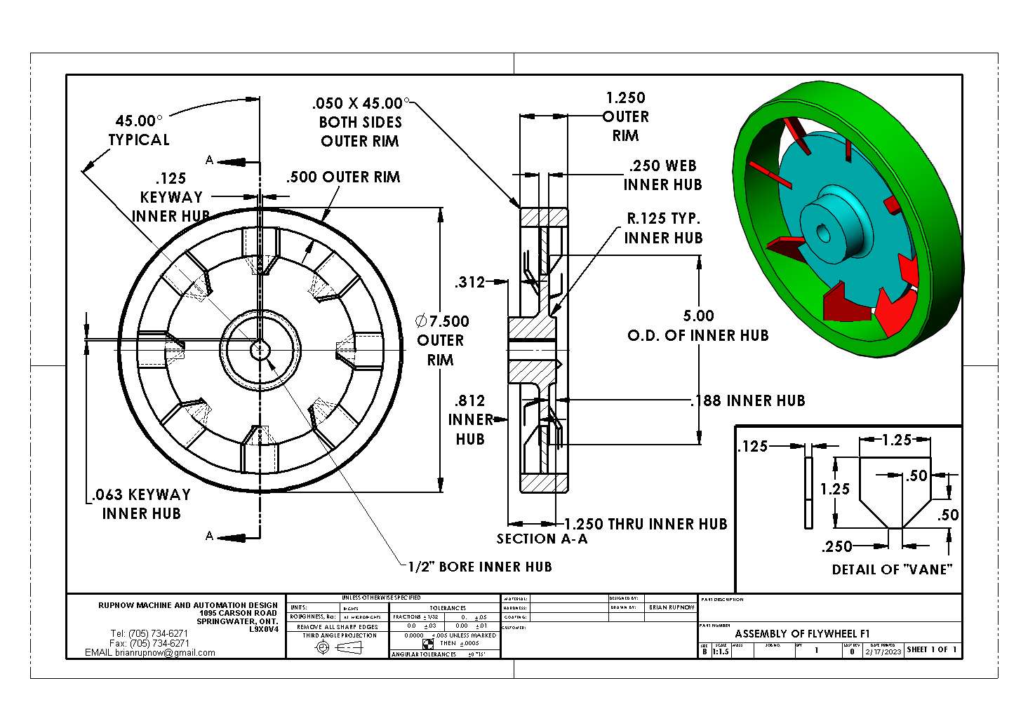
I want to start with something interesting and easy. The flywheel qualifies as fairly simple. Probably this will be the first part I make.---and if you noticed that it has no set screws, I will add them and update the drawing.
qAS2UO.jpg
 

Latest posts

Back
Top