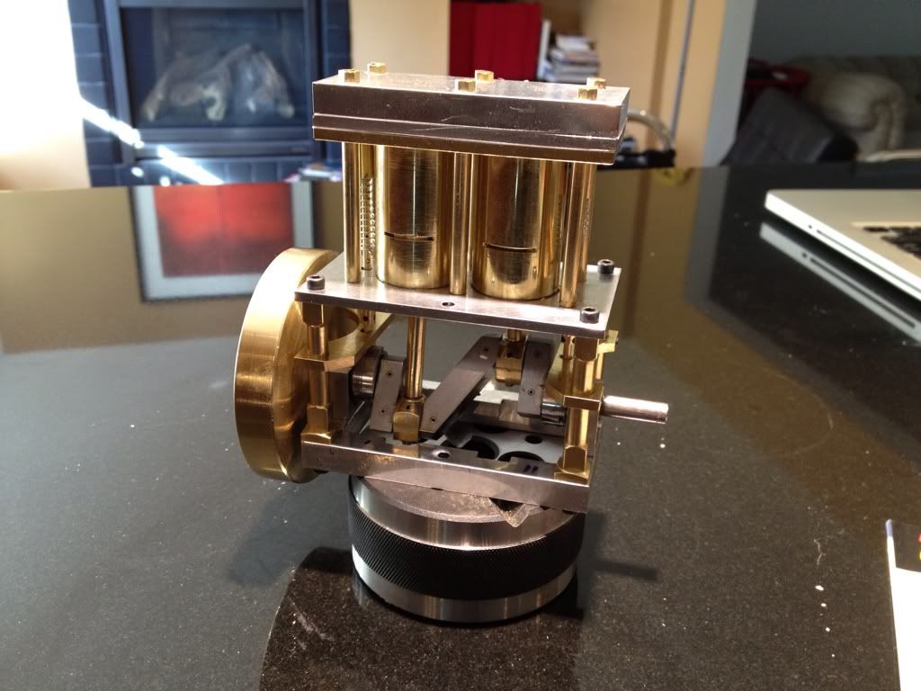
Elmer's 13 won't run

Home Model Engine Machinist Forum

Help Support Home Model Engine Machinist Forum:

This site may earn a commission from merchant affiliate links, including eBay, Amazon, and others.

Sshire

Well-Known Member
Joined
Jun 29, 2011
Messages
935
Reaction score
267
Any suggestions are welcome.
1. Engine turns smoothly by hand. No binding.
2. I've fixed all air leaks.
3. Cam position is correct according to Elmer's instructions
4. Timing is correct. When each piston is just beyond TDC the valve opens.
5. When the piston is at the BDC the valve trips and I can feel air exhausting from the correct exhaust port.
6. Used my usual airbrush compressor but it won't get above 10 pounds (when it's running the Grasshopper, I can adjust it to 25-30 pounds.
7. Went to the "big" compressor plenty of pressure but by the time I get it above 30 pounds, the hose blows off the engine.

Confused in Philadelphia
Stan
 
I know the frusration I have had engines stop running and take me a couple hours to figure out what went wrong. doulbe check the length of your valve and con rods if somthing istoo long or short it will throw thing out of wack . Just a guess. I know how easy it is to miss remember a dimension or miss measure.

Tin
 
Progress of a sort.
After checking everything for fit, tuning a few parts, and "grinding" the valve and seat (toothpaste, red polishing stick shavings and oil), I blocked the airflow to one cylinder. The other piston now pushes down by itself but won't come up because of back pressure. Did the same with the other cylinder with the same result.
So neither valve is closing completely. I removed the to valve plate and turned the flywheel by hand and with a 10x loupe both valves look closed when they are supposed to.
Has to be the valves.
I'm OK with remaking them both but I was very careful in setting the compound angle with a bevel protractor for the valve, so I would expect the same result. BTW I make the seat with a 90 degree end mill and the valve at 45 degrees on the lathe.
Anything I should consider prior to remaking the valves would be appreciated.
Best
Stan
 
You have a tough valve to get right. It has all the problems of an IC engine valve, and maybe even more because the stem dia is large relative to the head leaving little room for error.

You may have to do more grinding or lapping the valve with heavier compound than toothpaste.

Try putting some spotting blue on the valve and see if you can see where its actually touching, or not.

You might also try going very low on the air pressure, hoping to find a pressure that gets the piston down but doesnt provide much back pressure on the return stroke.

Note that the text makes several suggestions on timing and suggests you may have to take it apart and reassemble many times to get it right. You have probably the hardest steam engine valve Ive seen to get to work. God luck!
 
The valve seats have to be perfectly concentric with the valve guides to seal. I made a piloted cutter that fits very closely into the valve guide and cuts a 45 degree seat. I'n not sure what your valve seat material is, but if it's soft, a cutter made out of unhardened drill rod will work. I just cut a few slots on the 45 with a Dremel cut off wheel and ground a little clearance with a small stone. I turned it by hand- it worked great! (this is the way valve seats are cut on full size engines)
I'll try to post a picture soon.
Cheepo45
 
Ron
I'll try the low pressure. Elmer was the master of understatement with "take it apart a few times." Certain I can do it blindfolded.

Scott
A picture would be great. I'll absolutely try it.
Right now I have a very pretty finger engine. (place finger on flywheel and turn)

Best
Stan
 
Here are some pictures of the valve seat cutters I made. The ones with the holes use a snug fitting pilot in the valve guide hole. The other one has a built in pilot. They are made out of drill rod. I didn't harden them-I was only cutting aluminum.
It took a few tries (and a lot of disassembly and assembly!) to get the valves to seat on my Upshur farm engine.
That Elmer's # 13 is quite an ambitious project, Stan! How about some pictures?

DSCN1597.JPG


DSCN1598.JPG


DSCN1599.JPG
 
Scott
Thanks for the pictures. I'm going to make one for this engine for the valve redo.
Here's a pic.

46b97b7e.jpg


Last night I decided to build something less complicated in between remaking the new valves and seats. Started Elmer's Scotty. Hoping to get that done in a few days (almost as few parts as your Standby).

Going down to the shop to make your valve cutters. I'll report.

Thanks again
Stan
 
After looking at Cheepo45's valve seat cutters, I realized that if I didn't change the angle of the compound, and cut the valve at that setting, the angle of both will be identical and "should" be a perfect fit. So it wouldn't matter if the compound was at 45 or 44.12345 or 47.
A perfectly matching seat and valve!
Off to the shop.
Best
Stan
 
Ok but they should not be the same , the valve seat would be to wide they need to differ slightly to achieve a thin seat


say the seat is 45 deg and the cone on the valve is 45.5 deg then yo would only be seating on a fine line not the whole width of the seat as would be the case if they were the same


Th 1/2 degree interference between the valve and the seat is a good idea (and pretty much standard practice in rebuilding full size engines). This will give you a nice line contact between the two. The valve seat should only be about .005-.010 wide for best results with the small valve sizes we use on our models. With a concentric valve and seat and a little lapping, you should get a good seal. The light lapping will also insure that everything is concentric and sealing properly. I use a sharpie marker to color the seat and the valve to see the contact pattern.
 
Got it. I'll give the lathe a good kick. That should move it a half degree ;D
Best
Stan
 

Latest posts

Back
Top