Tony Bird
Senior Member
Hi,
Many small steam engines have been made to my own and other peoples designs. For the most part my designs have been modifications of other peoples ideas with no really new concepts added. A lot of the engines that have been made are of the simple oscillating type which have been used for railway locomotives, boats and as stationary engines to power things like air and water pumps. Some of the engine designs have been modified and used as the basis of oil and water pumps.
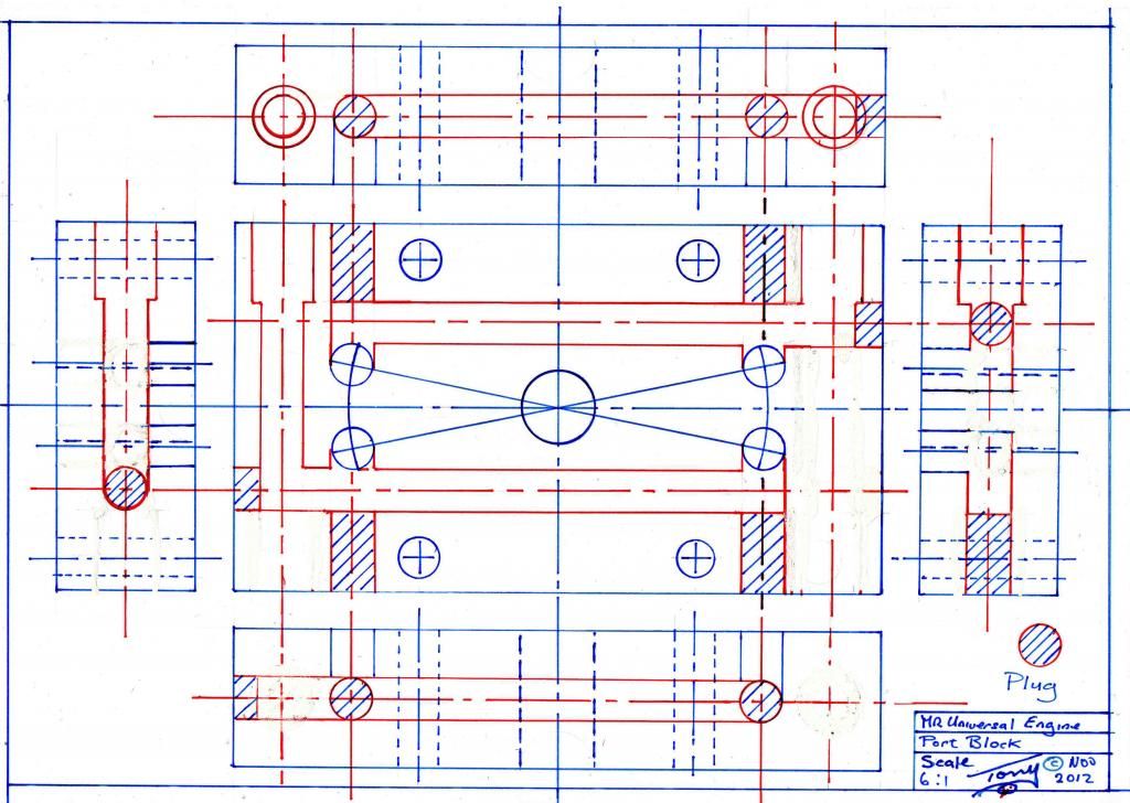
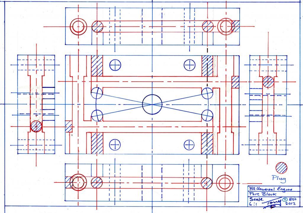
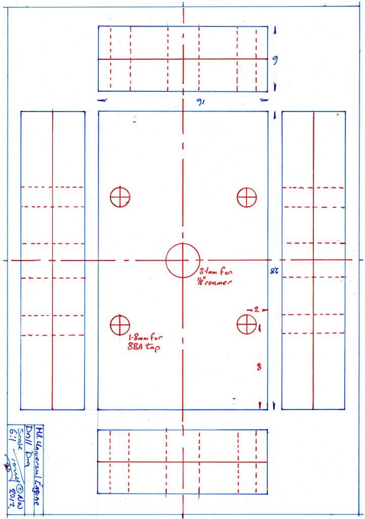
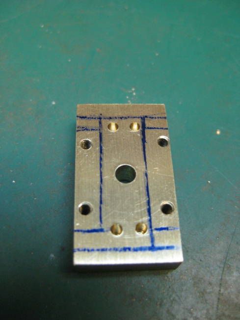
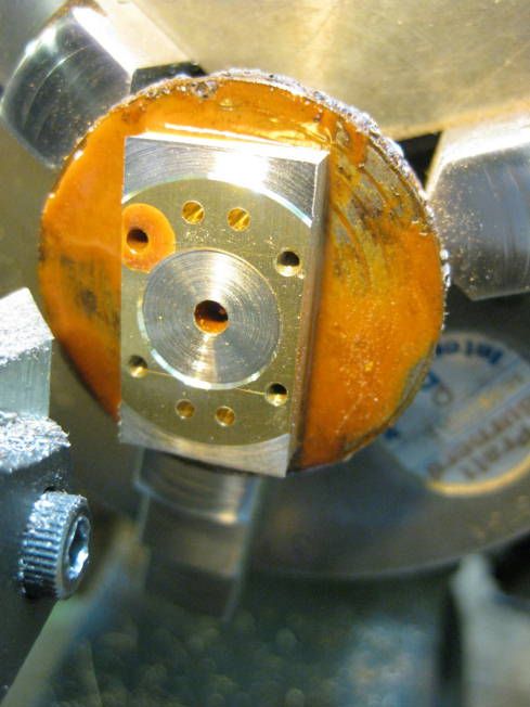
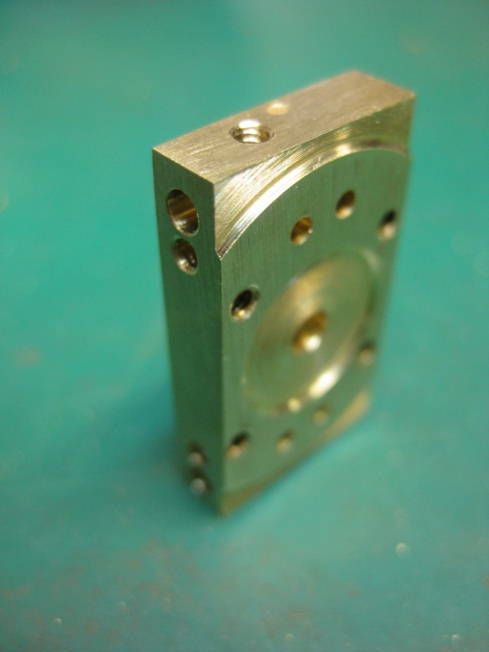
Some years ago two different size engines of the same design were designed and made. The idea behind them was for an engine that could be either be single or double acting with steam and exhaust pipes that could be placed on any the four sidesof its port block as well as on the back of it. The engines were to have either a 12mm or 18mm stroke (about ½ &¾) with the possibility of using various bores. The engines port block was designed to be assmall as possible and meet the above criterion. The smaller 12mm stroke engine having a 6mm thick brass port block 28 x16mm (about 1.1/8x 5/8), the larger 18mm stroke engines port block was also 6mm thick and 36 x 18mm (about 1.1.2x ¾). Many of these engines have been made and used for various applications.
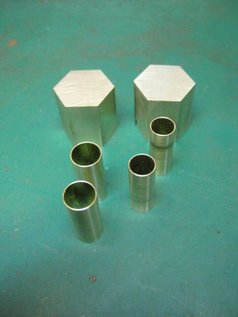
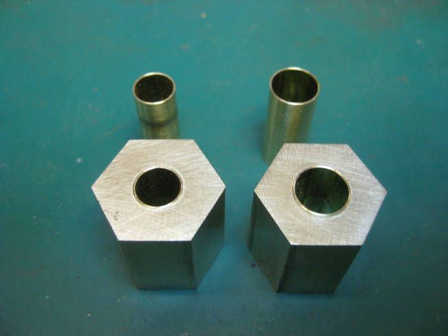
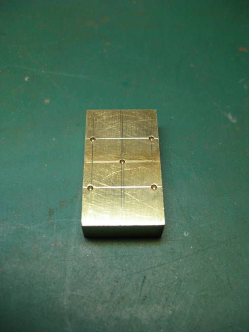
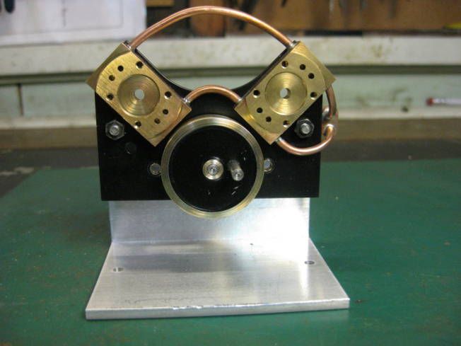
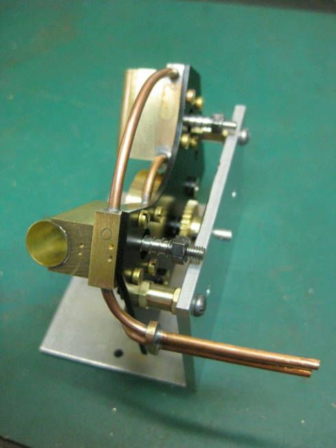
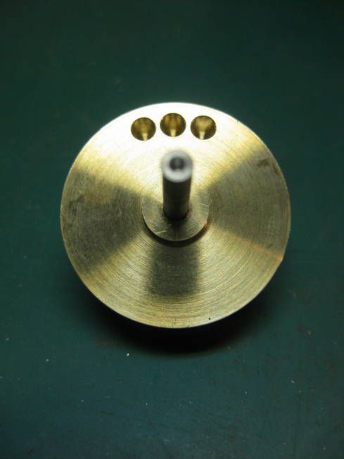
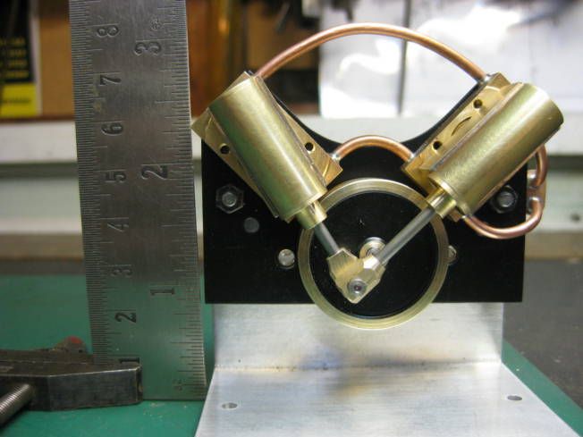
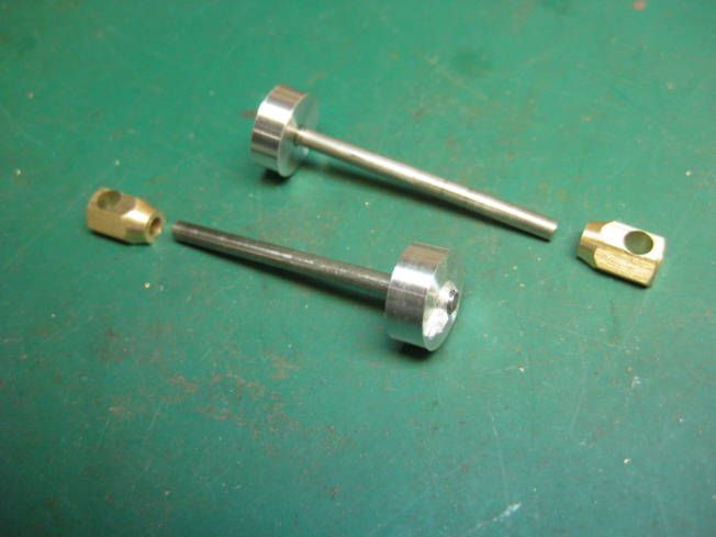
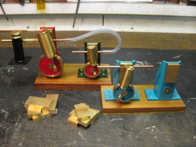
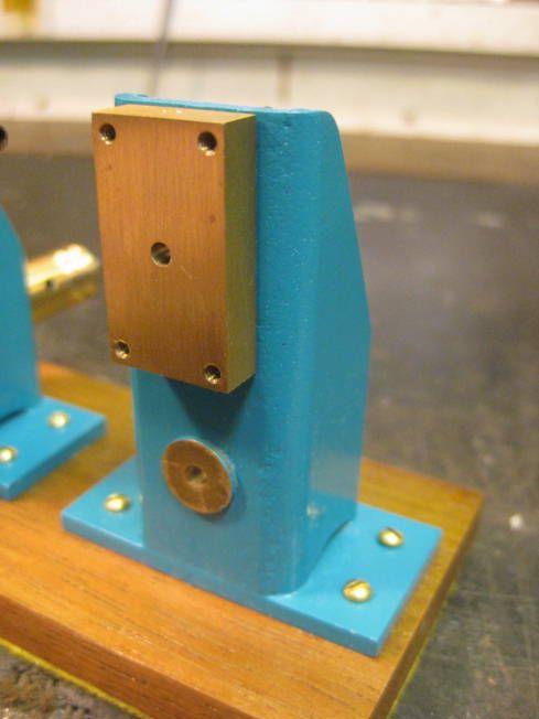
Attached are two photographs, one showing large and a small double acting engines, in front of them is a small single acting engine and a column with port block of a part built small engine. Also in the photograph are numbers of machined large and small port blocks along with a black lubricator used in engine tests, the other photographs is a close up of a small unfinished engine.
The next engine to be made is to fit onto a commercial Mamod boiler to make it into a power plant. The making and designing of the engine is very low tech. The drawings are produced on a sheet of foolscap paper using a childs drawing set and they look like it. What is hoped is that this thread will show model engineers with limited experience and tools how to design and make simple engines with just a lathe and hand tools.
The first thing is to produce a working drawing of the engine. Most of the engines that have been made using these size port blocks have been slightly different not just being single or multi cylinder but with different bores and dimensions.
The engine that is to be built is to be a small double acting type and made as short as practical. To make an oscillating steam engine shorter not a lot can be done about the length of the cylinder beyond a certain point. Reducing the centre distance between the axle and trunnion centres can make a difference to the LOA. But doing this will effect the sizes of other parts of the engine. Reducing the centre distance will increase the angle the cylinder travels through which will allow an increase in the size of the steam and exhaust ports. It will also increase very slightly the over all length of the cylinder. It will also if a flywheel crank is used reduce its size. The only down side of shortening the axle/trunnion distance is the increase in angular movement of the cylinder, which will cause more friction and possible, wear. Most commercially made and freelance models seem to have cylinders that have an angular movement of between 20 and 25 degrees, which produces a good balance between angular movement, friction and port size.
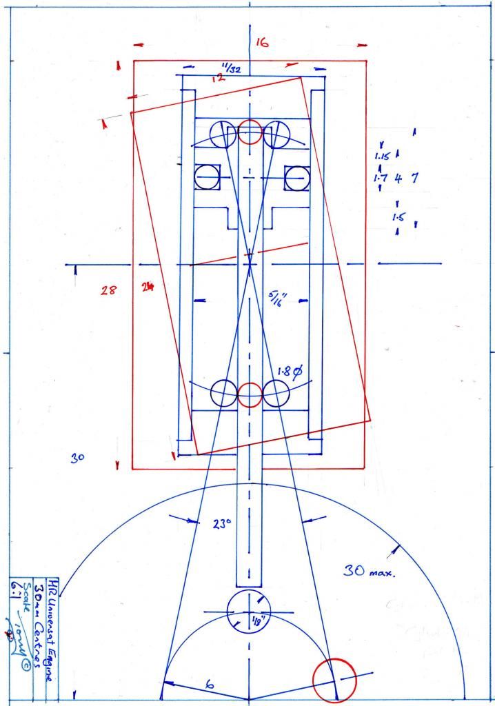
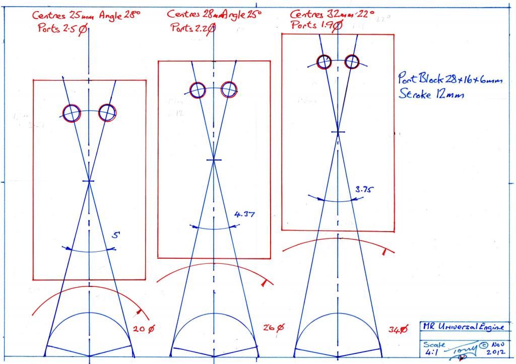
Attached is a drawing? Which shows the effect of altering the axle and trunnion centre distance through 32,28, and 25mm (about 1.1/4, 1.1/8 and1). The ¼ difference has quite an effect on the angular movement, port and flywheel crank size. This is the first R+D drawing for the engine, the centre (28mm) size will be used. I hope members find this thread interesting, it will probably go very slowly.
Regards Tony.
Many small steam engines have been made to my own and other peoples designs. For the most part my designs have been modifications of other peoples ideas with no really new concepts added. A lot of the engines that have been made are of the simple oscillating type which have been used for railway locomotives, boats and as stationary engines to power things like air and water pumps. Some of the engine designs have been modified and used as the basis of oil and water pumps.
Some years ago two different size engines of the same design were designed and made. The idea behind them was for an engine that could be either be single or double acting with steam and exhaust pipes that could be placed on any the four sidesof its port block as well as on the back of it. The engines were to have either a 12mm or 18mm stroke (about ½ &¾) with the possibility of using various bores. The engines port block was designed to be assmall as possible and meet the above criterion. The smaller 12mm stroke engine having a 6mm thick brass port block 28 x16mm (about 1.1/8x 5/8), the larger 18mm stroke engines port block was also 6mm thick and 36 x 18mm (about 1.1.2x ¾). Many of these engines have been made and used for various applications.
Attached are two photographs, one showing large and a small double acting engines, in front of them is a small single acting engine and a column with port block of a part built small engine. Also in the photograph are numbers of machined large and small port blocks along with a black lubricator used in engine tests, the other photographs is a close up of a small unfinished engine.
The next engine to be made is to fit onto a commercial Mamod boiler to make it into a power plant. The making and designing of the engine is very low tech. The drawings are produced on a sheet of foolscap paper using a childs drawing set and they look like it. What is hoped is that this thread will show model engineers with limited experience and tools how to design and make simple engines with just a lathe and hand tools.
The first thing is to produce a working drawing of the engine. Most of the engines that have been made using these size port blocks have been slightly different not just being single or multi cylinder but with different bores and dimensions.
The engine that is to be built is to be a small double acting type and made as short as practical. To make an oscillating steam engine shorter not a lot can be done about the length of the cylinder beyond a certain point. Reducing the centre distance between the axle and trunnion centres can make a difference to the LOA. But doing this will effect the sizes of other parts of the engine. Reducing the centre distance will increase the angle the cylinder travels through which will allow an increase in the size of the steam and exhaust ports. It will also increase very slightly the over all length of the cylinder. It will also if a flywheel crank is used reduce its size. The only down side of shortening the axle/trunnion distance is the increase in angular movement of the cylinder, which will cause more friction and possible, wear. Most commercially made and freelance models seem to have cylinders that have an angular movement of between 20 and 25 degrees, which produces a good balance between angular movement, friction and port size.
Attached is a drawing? Which shows the effect of altering the axle and trunnion centre distance through 32,28, and 25mm (about 1.1/4, 1.1/8 and1). The ¼ difference has quite an effect on the angular movement, port and flywheel crank size. This is the first R+D drawing for the engine, the centre (28mm) size will be used. I hope members find this thread interesting, it will probably go very slowly.


Regards Tony.


