Design and build side-shaft hit and miss engine from bar stock

Home Model Engine Machinist Forum

Help Support Home Model Engine Machinist Forum:

This site may earn a commission from merchant affiliate links, including eBay, Amazon, and others.
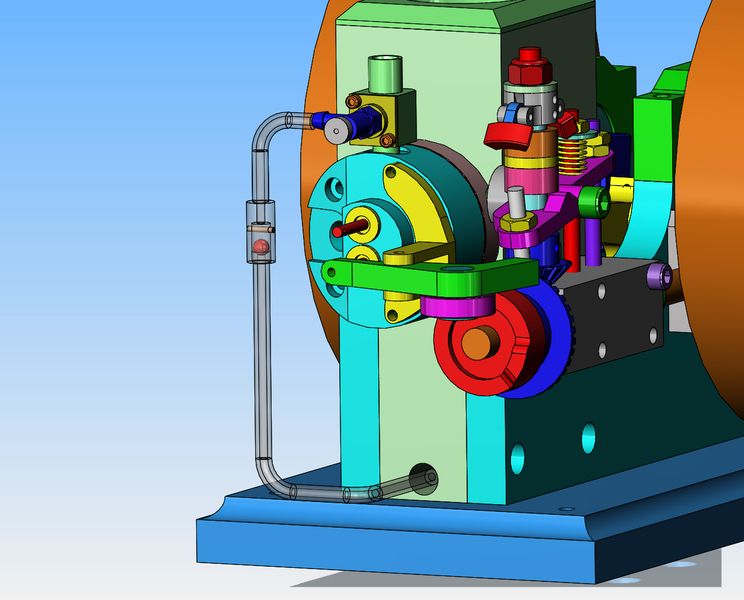
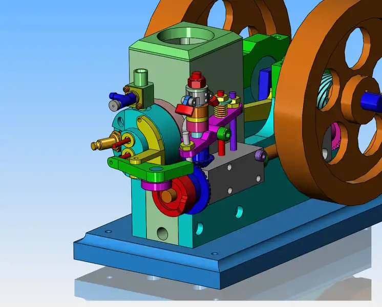
I haven't given a lot of thought about carburation nor exhaust yet. The rocker arm for the exhaust valve sets at the bottom of the head, so consequently the carburetor and intake valve will get the port closest to the top of the engine. I think that for a carburetor I will use a variation of Malcolm Stride's Jaguar carb, with the throttle removed and a solid carb body. My fuel line from the built in gas tank is going to run out from that hole in the very bottom of the cooling reservoir block, so it may be interesting getting a fuel line from down there up to where the carburetor is.
JhucqU.jpg
 
xx.gif

Re: Design and build side shaft hit and miss engine from bar stock
« Reply #144 on: Today at 12:02:29 PM »
Brian,
On most of the hit and miss engines the valve set-up is horizontal whether pushrod operated or by shaft like yours. The exhaust is generally to the outside with different configurations for the intake. On Associated engines there is a tower over the intake on which the exhaust pivots while on others like the Domestic side shaft the valves are staggered so the exhaust rocker arm can pass by. Stacking them like you have will still allow for an operating engine but will just look very different from conventional hit and miss designs.
gbritnell
 
My diamond lapping compound came in yesterday. This morning, bright and early before the Christmas crowd gets here I got up and diamond lapped the piston into the cylinder. I think it went quite successfully. the piston and the inside of the cylinder have taken on a dull grey finish, and the piston will not fall thru the cylinder, but will go with a slight push. If I hold my hand over one end of the cylinder and try to push the piston thru from the other end, it air-locks and won't go.
7RLLKT.jpg
 
very much enjoying this build. That is going to be an excellent piece of equipment when done. Looking forward to hearing it, Because that's the best part of a hit n' miss!!!
 
The Christmas crowd has come and gone, and I have reassembled the engine. Everything goes round and round, and has amazing compression when I seal the end of the cylinder with the palm of my hand. This is a good sign.
 
For anybody that didn't quite get it about the gas line----These small engines will lift fuel at least 1" up from a tank, due to the vacuum created by the venturi in the carburetor. However, when the engine goes into it's "miss" cycle and no air is being pulled in thru the carburetor, the vacuum disappears---and all the gas in the line will run back down into the tank due to gravity. Then when the engine has slowed down enough to "hit" again, it can't because the gas has all ran down into the tank. To prevent that from happening, a check valve is installed in the vertical portion of the gas line. This check valve allows gasoline to flow from the tank towards the carburetor, but as soon as the gas tries to flow back down into the tank, the orange colored ball "seats" in the conical portion of line just below it and won't let the gas run back to the tank. When the engine slows down enough to want to "hit" again, it has a supply of gas right there waiting for it.
Bj7872.jpg
 
The time has come, the Walrus said, to speak of many things---And the only two major parts left are the cylinder head and the face cam. I will stick with something that I know relatively well, and make the cylinder head.
12F2G6.jpg
 
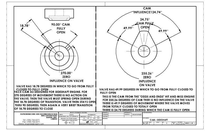
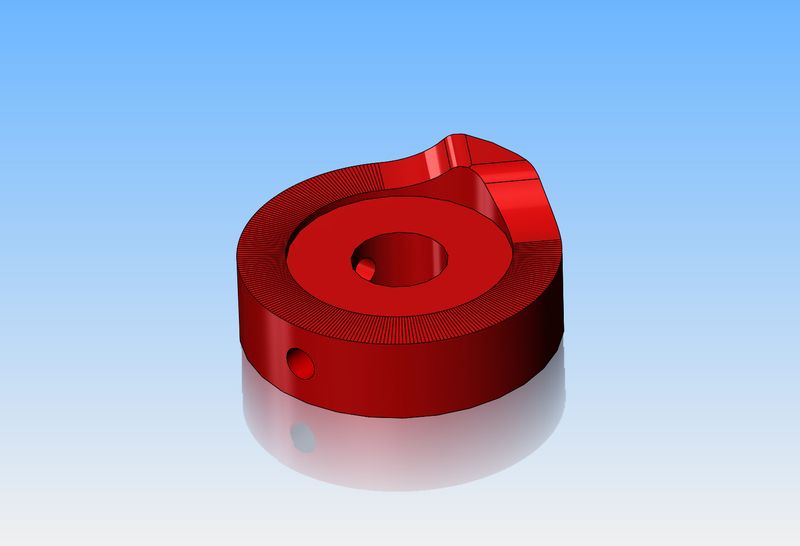
This is my first shot at designing a face cam. On the right you can see the conventional can for the "odds and ends" hit and miss engine. On the left is the face cam for the sideshaft engine I am designing.--Opinions please.--Brian
0J3TcF.jpg
 
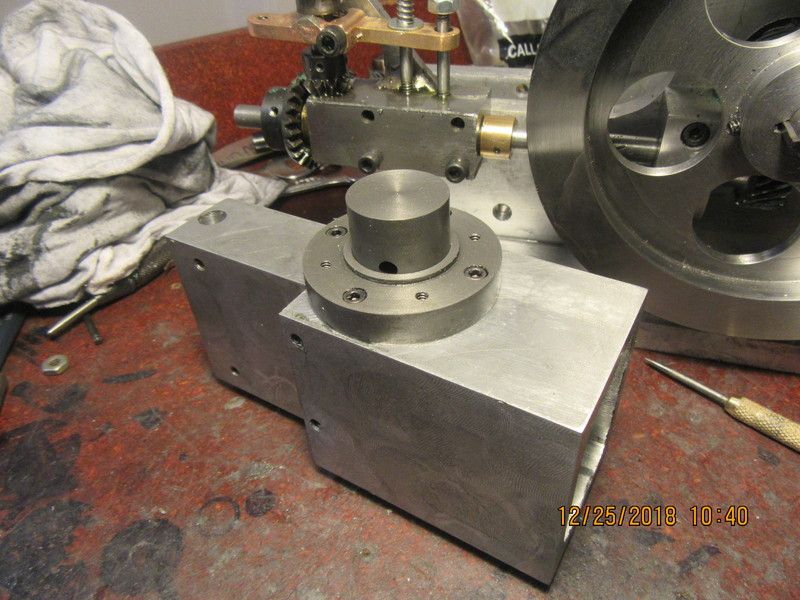
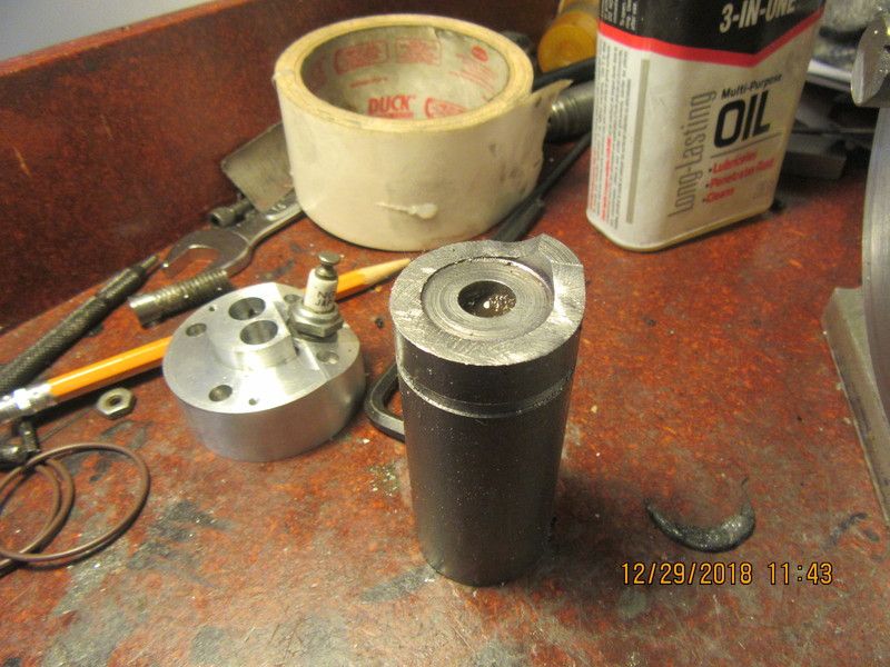
A good start was made on the cylinder head today. All of the lathe work is now finished, and the next move will be over to the milling machine.--A little story here--I have two metal suppliers in Barrie. One is a fab shop that's been around forever, they do excellent work, and they sell material over the counter. My other supplier is a young guy who does nothing except warehousing and selling material cut to length. I wanted a 1 foot length of 2 1/4" diameter aluminum. The young guy is shut down for Christmas holiday. I went to the fab shop today, and asked "How much for a 1 foot length"? The answer was $17.00. Okay, I can live with that. BUT---Unless I can find a "short" out by the rack, there is going to be a fifteen minute minimum labor charge if somebody has to cut it for me. The fifteen minute labor charge would be $18.00 The labor charge would be more than the material. I said "Screw it!" and came home and whittled my cylinder head out of a piece of plate.
KigO1p.jpg
 
Very interested in your cam design.
I have been looking at a 2 cylinder engine remake.
knox2.JPG
 
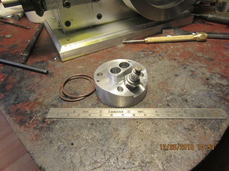
So--Here we have it---a beautiful cylinder head. All the holes ended up in the right place. When I went to use my electronic angle finder to measure the 20 degree sloping face, the battery was dead. Trying to get the back open to put in a new battery broke the plastic housing. I have an old gravity actuated angle finder that I used instead. It's kind of critical, because if the angle is off by much, the spark-plug hole which is drilled blind can come out into the valve guide holes and that is very bad ju-ju. I was lucky, and the sparkplug hole come out on the far side exactly where it was supposed to. You will also see, setting beside the cylinder head, a pair of Viton O-rings which will seal the interface between the outside of the cylinder and the water reservoir.
E7TUYY.jpg
 
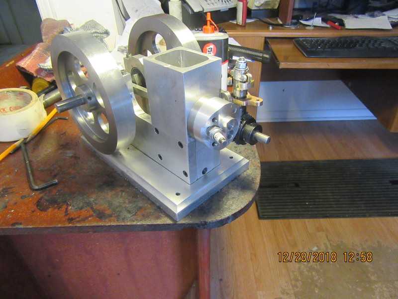
With cylinder head finished and bolted in place, and cylinder o-ringed and siliconed into water reservoir, this thing is beginning to look like an engine. Very soon I'm going to have to dive into the unknown and make a face cam. George Britnel and Jason have been guiding me along on this. I'm still not certain I have the total picture sorted out in my head, but I'm running out of parts to make. One good thing is that these parts (the cam follower and face-cam) are on the outside of the engine, so if I mess something up, I don't have to tear the entire engine down to correct it.
Mykc44.jpg
 
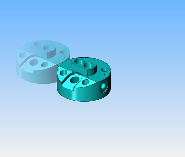
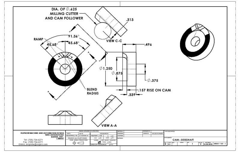
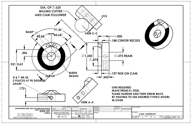
After much heavy thinking and going slightly crazy in the process, I decided to let the power of my Solidworks software do this face cam thing for me. The area which appears as solid black in the drawing is flat, representing the area where the valve will not be influenced by the cam. I have decided to cut the profile with the side of a a 5/8" endmill and to use a 5/8" diameter cam follower. I greatly appreciate the help I received from Jason and from George Britnell.----Brian
3SahP0.jpg
 
Today I'm going to try something a little different, and make the face cam. It is definitely different than anything I've machined before, and should make for an interesting day. I will post pictures as it develops. First we start out with a solid model, and then using the math data from the model I will machine the part.
BVIZrV.jpg
 
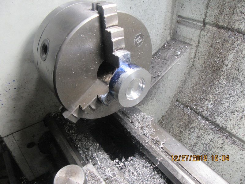
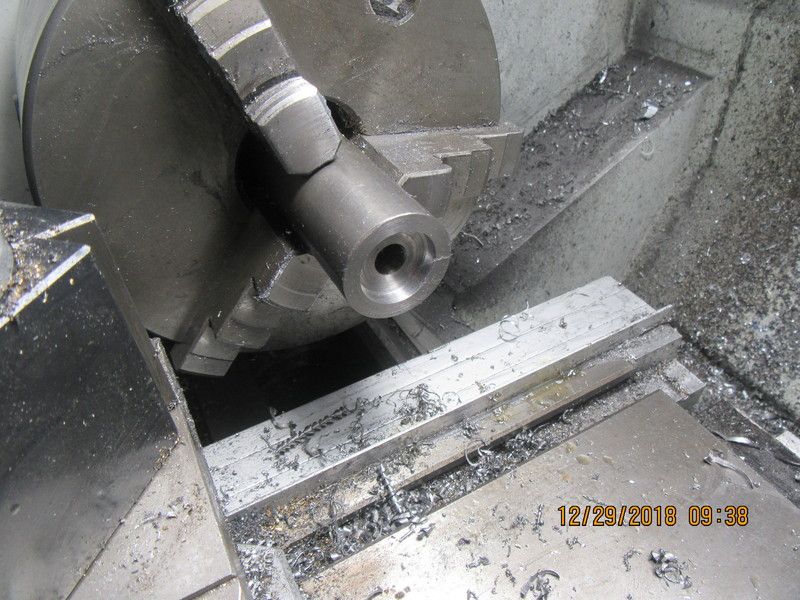
I know from my drawing that the outside diameter of the face cam is 1 1/4". I found a piece of 1 1/4" dia. cold rolled steel and chucked it up in the three jaw, and took a couple of passes to clean up the end. I also know that the face cam will be 1/2" thick, with a 3/8" dia. hole thru the center. so--I drilled and reamed a 0.375" dia. hole 0.8" deep in the end of the piece of steel. I also know that there will be a 7/8" diameter recess by 0.188" deep in the face, so a 7/8" diameter milling cutter was held in the tailstock chuck and plunged 3/16" deep. If I wanted to, I could now part off the piece to the thickness I need.--However--I know there will be some rotary table work before I'm finished, so I will leave the piece about 3" long to give a "chucking stub".
brA7Mf.jpg
 
With a couple of dimensions added to the drawing, I can see that a very large portion of the face cam is flat, with no curvature to it. That is the 0.931" dimension on the left side of the drawing. So, with the part held vertically in my rotary table chuck, I will machine that flat area away to a total of 0.157" deep.
wO8iSo.jpg
 
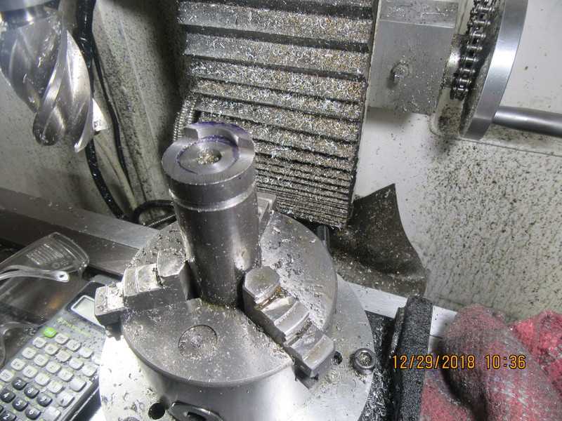
The part has been set up vertically in the 3-jaw chuck on my rotary table, and all of the "flat" area has been cut away to a depth of 0.157". The small remaining bit that hasn't been machined away is going to become the actual profile.
pFi0Os.jpg
 
Once the preceding steps have been accomplished, it comes down to basically 2 plunge cuts with a 5/8" endmill. Of course there is a bit of head scratching as to just where the plunge cuts have to be. Once they have been completed, the face-cam looks like this. Only one profiling step left, and that is using a file to "break" the sharp corners at the beginning of the remaining "lobe" area.
8C6wbo.jpg
 

Latest posts

Back
Top