CO2 Engine Design

Home Model Engine Machinist Forum

Help Support Home Model Engine Machinist Forum:

This site may earn a commission from merchant affiliate links, including eBay, Amazon, and others.

majorm

Junior Member
Joined
Nov 6, 2012
Messages
23
Reaction score
1
I have been reading a few posts on here trying to get some info on engines built using CO2 as a power source and ran across JAndrew's thread on air engine design. I dont want to stry his thread so I figured I would start a new one. It had some pretty good info design wise and answered some questions I had on piston diameter vs stroke and its effect on power. One poster noted a certain design but excluded CO2 engines as being different (unless I read it wrong).

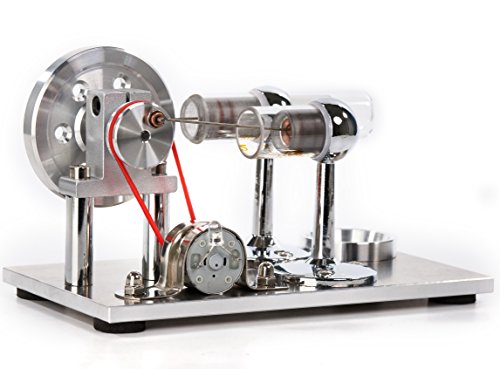
On that note how are CO2 engines made? What pressures do a gas and diesel full size engine normally run in the cylinder? Turbines are past my skill level but a piston engine would be interesting. I read over the post about making the desktop CO2 engine for a son but that was about all I saw.

How would you handle heating the engine so it doesn't just freeze up? Looking at the CO2 phase diagram if you could keep the system pressurized to 100 psi it wouldn't turn to a solid. However it will be below zero temperature wise. Are there certain plastics or other materials you think would be good candidates to use?

Thanks for any help or ideas.
 
I am not sure of your goal here .

Are you wanting to build a CO2 engine or wanting to design your own ?
Here is a basic plan set. Read it over I think it will answer many questions.

David Kerzel Modular 1 plans


On that note how are CO2 engines made?

See above plan set!!

What pressures do a gas and diesel full size engine normally run in the cylinder?
isnt the real question:: What is the vapor pressure of CO@ 20deg C the answer to that is 837 PSI.


The valving and cycles on a CO2 engine is different from both IC and steam.

the intake valve is a small ss ball seated at the top of the cylinder. it is held in place by a spring and the CO2 pressure, there is a hard rod on top of the piston when the piston reaches top dead center the rod bumps the valve allowing a momentary release of CO2 into the cylinder the gas presses on the piston surface and expands. when the piston reaches the bottom of the stroke there is a slot or series of holes that allow cylinder pressure to equalize with the surrounding atmosphere.The piston then returns to the top of the cylinder and compresses an air of CO2 in the cylinder.
So a CO2 engine is a two stoke of sorts. compression and power.
there is no exhaust stroke or intake stoke.

How would you handle heating the engine so it doesn't just freeze up?
I am not aware of any need to heat the cylinder.

Are there certain plastics or other materials you think would be good candidates to use?

Aluminum steel brass the common materials used for most engines.

Tin
 
Thanks for the thorough answer.

My goal is to one make a engine to try out (probably the one you posted now) and to make a three or four cylinder version of my own design. I have seen some engines made how you are describing using a bearing and pin as a pressure valve. It seems like that would give you a pretty weak pressure burst compared to something that stayed open for say 3/4 of the stroke.

As for the real question on the cylinder pressure....Im not smart enough to know if thats what I was asking for or not. I was just getting at are there any general numbers that people consider average for a common diesel and gas cylinder during combustion. I did find this "Combustion / Expansion Stroke: This stroke is where the spark plug ignites the air/fuel mixture, creating very high cylinder pressure which rise very quickly. Peak cylinder pressures near TDC (where spark occurs) will be in the range of 300 psi for engine's at light loads, to 1000 psi for production engines at full power to 1500 psi or greater for race engines. This is where the engine's power comes from, as it forces the piston down. As the piston goes down, the cylinder volume increases which reduces the cylinder pressure. When the piston gets to the bottom on the cylinder (BDC) there may only be 100 to 500 psi in the cylinder." At http://performancetrends.com/Definitions/Cylinder-Pressure.htm

For the cylinder heating do you think its the compression of the air after venting the CO2 that is giving it enough heat to not freeze?

For materials I was thinking of anything that may not require lubrication (or as much) and something that is fairly stable temperature wise.

Thanks again for the great reply as always.
 
I had a go at building a v-twin CO2 engine from a Kerzel plan a few years back, and wanted to scale it up 2X. That didn't work at all for me. The physics of the engine require that the momentum of the engine deliver enough force to raise the ball valve. I discovered that I would need a very massive flywheel to make that happen. And that was running on air.
 
Thanks for the thorough answer.

My goal is to one make a engine to try out (probably the one you posted now) and to make a three or four cylinder version of my own design. It seems like that would give you a pretty weak pressure burst compared to something that stayed open for say 3/4 of the stroke.


I had the same thought a few years back. I did a V8 with the ball valves that are opened by a pin in the piston. I went back and designed another that uses a cam shaft to lift the balls thinking the valve would stay open longer and I would get more power. I got around to making the block and some parts for the heads but never finished the engine.


This is the finished V8
DSCN1292s.jpg~original

DSCN1661.jpg~original


These is the concept for the cammed engine.
V8-2-2.jpg~original

V8Air4.jpg~original
 
Members:

Do you think any of the Liney/Chuck Fellows compressed-air engines would work with CO2? If yes, would you need a BIG tank of CO2 to run, for example, the opposed-four boxer engine?

Do you think a piston-valve, uniflow steam engine, like the "Little Husky" would spin on CO2? Is CO2 more expansive than compressed-air?

******************************************************************************************************

@kvom:

The Kerzel V-Twin/CO2: Interesting engine design, ( see: Florida AME/Gallery...."Non-Combustion Engines"), but you needed a much larger heavier flywheel. Do you think the engine would work as designed, if one were to use a heavier flywheel? Why did you abandon the tweaking of your double-size version of the Kerzel engine? Just curious.

****************************************************************************************************


Frank
 
CO2 is more expansive than air from what I have been reading. Thats why it caught my attention. If i recall correctly CO2 will expand about 3000% from liquid. Air and steam are less than half that unless I missed some detail. For the engine I wanted to design and make I was going to preheat (expand) the liquid/gas by heating it in a pressure vessel. Then I wanted to use a solenoid valve or something faster acting rather than the piston mounted valve pin. This means the engine would have to be larger but It allows you to feed the engine with a longer burst of pressure and a burst you can control. An alternative to a solenoid could be as simple as a twisting or rotating hollow rod with a cut in the side to let in the CO2 for a certain amount of time depending on the size of the hole.

Stevehuckss396: You have to finish that engine somehow. That looks great.
 
For the engine I wanted to design and make I was going to preheat (expand) the liquid/gas by heating it in a pressure vessel.

Why??? do you have a death wish or desire dismemberment ??

Preheating the vessel would not expand it it will dangerously increase vessel pressure.

Then I wanted to use a solenoid valve or something faster acting rather than the piston mounted valve pin.
The whole purpose of the tried and true CO2 engine design is a high power to weight ration and a siple easy design to machine. why overcompecate such a simple elegant working design and add a lot of extra weight.

This means the engine would have to be larger but It allows you to feed the engine with a longer burst of pressure and a burst you can control.
This is in direct contradiction of your last statement. A longer valve opening defeats the purpose of using an expansive gas and destroys the efficiency of the design.

An alternative to a solenoid could be as simple as a twisting or rotating hollow rod with a cut in the side to let in the CO2 for a certain amount of time depending on the size of the hole.

If you want to regulate the flow of CO@ on a desk model why not us a regulator. would that not be a logical tried and true solution.

If you are interested in CO2 engines fine. learn about how they are made and build a few. But please the idea of reinventing something you know nothing about is down right scary. Halloween is comming up but pleas no photos of mutilated hands.

Tin
 
Most CO2 cylinders are only designed to safely withstand 130 to 140 degrees F max. If you exceed this temperature, you may very likely have a pipe bomb sitting in front of you – not good!

That being said-

If you were to place the CO2 cylinder (and a portion of the high-pressure supply tubing) within a bucket a warm water (nothing hotter than you can comfortably place your hands into - 110 degrees F max), then you’ll increase efficiency of the motor. It will ensure that all of the CO2 flashes into a gas prior to entering the motor, and you'll get a greater rate-of-expansion from the CO2 during the power stroke.

Don't even think about using a flame on the cylinder, or any temperature too hot to touch!
 
Adding fins to the head and cylinder would allow for increased heat transfer and minimize the cooling effect of the expanding gas.

It may also be possible to use a set screw type device to adjust the height of the valve mechanism this could allow for minor adjustments in how long the valve is open.
That said.
Again I encourage build tried and true designs before you try to reinvent or improve on the design.
Tin
 
Enthropy455 I know what you mean about the heat and pressure. Even back in my paintball days I remember keeping the CO2 tanks, when we used those, out of the sun. I wouldn't heat the main cylinder but maybe a small volume in the supply tube. I talked with my swagelok rep one day about how much pressure their tube could handle at certain temps back when I was looking at steam. He gave me a table showing the max pressure correction for certain temps. The pressure capability drops off FAST once heat is considered. I think I was a little misleading saying pressure vessel. Its definitely an area to approach slowly and warm water would be the way to go if i decide to try it. I would want to put a pressure transducer or gauge on it though to somehow quantify where it was pressure wise.

Tin Falcon: Ill definitely build a known design before I actually make something of my own design.
 
http://www.animatedengines.com/co2.html

You may want to try to find a deal on an old "AIR Hogs" engine these engines run on compressed air , are made of clear plastic, and these engines are essentially of the same design as a CO2 engine.


I ask again what is your goal in all of this. You seem bent on performance enhancements. What application are you intending ??. you speak of a desk model. If you simply have an engine working on a desk added weight is not an issue be neither is max performance.

If you intend on using the engine in an aircraft, then performance would be desirable but added weight of water or other items reduce the power to weight ratio.

IMHO the only logical application for a CO2 engine with added hardware is on a land or water craft.
So have fun and be safe things blowing up near flesh is not fun or safe. Getting hurt is not fun.
Tin
 
My intentions are two fold. I want to initially build a small desktop engine to get a basis for how it works. Then from there make some different versions to test out how they perform. I do realize a scaled engine wont necessarily work like a full size one. After I can get my head around how various ideas I have work then move onto something larger. I may try to make a lawn mower engine or something to run a belt sander. Just something as a proof of concept to see how it works. If that works out then move up to something larger like a boat engine. That would be well down the road though.

Looking into improving performance is just how my brain works. I have a hard time just leaving something alone and have always been like that. For a desktop model your right on performance not really being a big factor but since its more of a learning thing and could progress into a larger engine i'm looking into performance.

I definitely agree on the bodily injury warnings. Thats the last thing I need or want to happen so safety is a priority.
 
I have a 20# CO2 tank that I use mainly for airing up offroad tires, although I've also used it to run nail guns when building my shop. The tank has a regulator, so that normally the output is at about 80 psi.

When I tried to get the larger CO2 engine to run, I just used compressed air; CO2 wouldn't have main a difference. I assume the term CO2 engine came from using CO2 cartridges to run engines om moving vehicles such as boats.

On my aborted build, I actually had tried it at 3X scale, not 2X. The issue is that having a ball with 3X the diameter for a valve means 9x the surface area, so 9X the force acting on the ball. I could barely rotate the crank with the air applied. Then two, the piston area was 9X but it's mass was 27 times. I gave up at that point. The reality was that I wanted to build a larger scale model at that point in time. As designed by Kerzel the engine might be at the sweet spot for a good runner.
 
Here's my last post on the build thread that summarized my thoughts:

Here are the issues as I see them:

1) The ball has to be small, otherwise the pressure acting on it will be too great for the pin to lift

2) If the ball is small, the the inlet hole is also small, limiting the input gas flow into the chamber.

3) The lift has to be small. If it's too high then the gas enters to early in the cycle and kicks the piston opposite the way it needs to go. But when it's low then issues 1 and 2 come into play.

The 3x scaling problems are these:

1) The chamber diameter is now 3**3 larger, or 27 times the volume of the original scale. That means 27x more gas needs to enter to result in the same pressure.

2) If I could scale up the ball and hole 3x then it would allow 8x the flow. But I would also have 8x the force acting on the ball.

3) The mass of the piston/crank assembly is also 27x the original, meaning the for a given pressure in the chamber I would have a smaller velocity.

The only "solution" that would seem to have a chance is to have an extremely heavy flywheel whose momentum could carry the cycle around, and the pressure would likely need to be quite high as well.
 
Why dont you just to a different style valve and do away with the bearing as the valve? That would fix the issue of the bearing size and weight and should allow the engine to start and stop getting pressure at the right time. How to make a sealed valve is another issue but should be doable. It complicates the build but should make it move up in size easier. If it came down to it you could just use a solenoid with a magnetic switch that was actuated by magnets on the flywheel. Then you're introducing the need for another power source too though. Ill think some more and see if I can come up with anything cleaner looking.
 
Some things do not scale well. IMHO the size (scale range) of CO2 engines is limited. They have been successfully used to power small aircraft. They are a cool engine type and it is relatively easy to make multi cylinder designs of various types v twins, radials , straight inline, boxers etc. and as Steve has shown a V-8.
If you have really small machines CO2 engines are neat little projects and as I said are well suited to power small models.

If your goal is to scale up and power things maybe you need to think about IC engines diesels etc. Tin
 

Latest posts

Back
Top